

Imagine communications CMN-91 Installation And Operation Manual

CMN-91
Compact Video and Audio Monitor
Revision D
March 2013
Installation and Operation Manual

CMN-91 Compact Video and Audio Monitor Installation and Operation Manual
© 2016 Imagine Communications Corp. Proprietary and Confidential. Revision D | Page 2
Publication Information
© 2016 Imagine Communications Corp.
Proprietary and Confidential.
Imagine Communications considers this document and its contents to be proprietary and confidential.
Except for making a reasonable number of copies for your own internal use, you may not reproduce this
publication, or any part thereof, in any form, by any method, for any purpose, or in any language other
than English without the written consent of Imagine Communications. All other uses are illegal.
This publication is designed to assist in the use of the product as it exists on the date of publication of
this manual, and may not reflect the product at the current time or an unknown time in the future. This
publication does not in any way warrant description accuracy or guarantee the use for the product to
which it refers. Imagine Communications reserves the right, without notice to make such changes in
equipment, design, specifications, components, or documentation as progress may warrant to improve
the performance of the product.
Trademarks
Product names and other appropriate trademarks, e.g. D-Series™, Invenio®, PowerSmart®, Versio™ are
trademarks or trade names of Imagine Communications or its subsidiaries.
Microsoft® and Windows® are registered trademarks of Microsoft Corporation. All other trademarks and
trade names are the property of their respective companies.
Contact Information
Imagine Communications has office locations around the world. For domestic and international location
and contact information, visit our Contact page (http://www.imaginecommunications.com/howbuy/contact-us).
Support Contact Information
For domestic and international support contact information see:
Support Contacts (http://www.imaginecommunications.com/how-buy/contact-us)
Worldwide Support e-mail (mailto: service@imaginecommunications.com)
Customer Community Portal (http://app.imaginecommunications.com/customercommunity)
Warranty & Contract Information (http://www.imaginecommunications.com/services/customer-
care)
MyImagine Academy Training (http://www.imaginecommunications-academy.com)
Product Manuals (http://www.imaginecommunications.com/services/product-manuals)

CMN-91
Installation and Operation Manual Contents
© 2016 Imagine Communications Corp. Proprietary and Confidential. Revision D | Page 3
Contents
About This Manual ............................................................................................... 10
Intended Audience ................................................................................................................................. 10
Finding Specific Information in This Manual .......................................................................................... 10
Manual Information ............................................................................................................................... 11
Revision History .................................................................................................................................. 11
Writing Conventions ........................................................................................................................... 11
Obtaining Documents ......................................................................................................................... 12
Unpacking/Shipping Information ........................................................................................................... 12
Unpacking a Product .......................................................................................................................... 12
Product Servicing ................................................................................................................................ 12
Returning a Product ........................................................................................................................... 12
Operator’s Safety Summary ................................................................................................................... 13
Ensuring Safety ................................................................................................................................... 13
Explanation of Symbols ...................................................................................................................... 14
Certification Labels and Symbol Locations ......................................................................................... 14
Directives and Compliances.................................................................................................................... 14
Restriction on Hazardous Substances (RoHS) Directive ..................................................................... 15
Waste from Electrical and Electronic Equipment (WEEE) Directive .................................................. 15
Introduction ......................................................................................................... 17
Product Features .................................................................................................................................... 17
Standard Features .............................................................................................................................. 17
Optional Features ............................................................................................................................... 18
Video Formats Supported....................................................................................................................... 19
Front Panel and Back Panel Views .......................................................................................................... 23
Safety ...................................................................................................................................................... 24
CMN-91 Service and Support ................................................................................................................. 24
Installation ........................................................................................................... 25
Installation Procedures ........................................................................................................................... 25
Inspecting the Shipment .................................................................................................................... 25
Installing the Optional Battery to Power the CMN-91 ........................................................................... 25
Installing the Optional Battery Mount ............................................................................................... 26

CMN-91
Installation and Operation Manual Contents
© 2016 Imagine Communications Corp. Proprietary and Confidential. Revision D | Page 4
Charging the Battery .......................................................................................................................... 26
Rack Mounting the CMN-91 ................................................................................................................... 27
DRC-3 Rack Mount Installation .......................................................................................................... 27
DRC-3 Rack Mount with Rack Extensions Installation ........................................................................ 28
DRC-2A Rack Mount Installation ........................................................................................................ 30
Connecting the CMN-91 ......................................................................................................................... 32
Ethernet Setup ........................................................................................................................................ 33
Using the IP Configuration Utility ........................................................................................................... 35
Installing the Utility ............................................................................................................................ 35
Using the Utility .................................................................................................................................. 36
General Information ............................................................................................ 39
Terms ...................................................................................................................................................... 39
Controlling the CMN-91 .......................................................................................................................... 39
Front Panel Controls ........................................................................................................................... 40
Web-Based Panel Controls ................................................................................................................. 42
Remote Control Panel Controls .......................................................................................................... 45
Setting Up Sleep Mode ........................................................................................................................... 45
Selecting Inputs ...................................................................................................................................... 46
Display Selections ................................................................................................................................... 46
Full Screen Display .............................................................................................................................. 47
Quad Display ...................................................................................................................................... 48
Overlay Display ................................................................................................................................... 49
Main Title Bar ..................................................................................................................................... 50
Icons ................................................................................................................................................... 50
Status Bar ........................................................................................................................................... 51
Selecting an Internal or External Reference ....................................................................................... 51
Selecting a Function ........................................................................................................................... 51
Accessing and Navigating the Setup Menu ............................................................................................ 52
Capturing a Display ............................................................................................................................. 52
Storing a Captured Display ................................................................................................................. 52
Recalling a Captured Display .............................................................................................................. 53
Clearing a Captured Display ............................................................................................................... 53
Capturing Display Data ....................................................................................................................... 53
Storing Captured Data ........................................................................................................................ 54
Recalling Captured Data ..................................................................................................................... 54
Clearing Captured Data ...................................................................................................................... 54
Operation ............................................................................................................ 55
Waveform Display .................................................................................................................................. 55

CMN-91
Installation and Operation Manual Contents
© 2016 Imagine Communications Corp. Proprietary and Confidential. Revision D | Page 5
Waveform Front Panel Selections ...................................................................................................... 58
Vector Display ......................................................................................................................................... 63
Vector Front Panel Selections ............................................................................................................ 68
Gamut Display ........................................................................................................................................ 72
Composite Gamut .............................................................................................................................. 74
RGB Gamut Display ............................................................................................................................ 76
Placing the Gamut Display in Line Select Mode ................................................................................. 77
Setting Display Options ...................................................................................................................... 78
Gamut Setup Menu ............................................................................................................................ 78
Picture Display ........................................................................................................................................ 79
Placing the Picture in Line Select Mode ............................................................................................. 80
Picture Setup Menu ............................................................................................................................ 81
Moving a PIP ....................................................................................................................................... 82
Scaling a PIP ........................................................................................................................................ 82
Removing a PIP ................................................................................................................................... 82
Audio Display .......................................................................................................................................... 83
Audio Scales........................................................................................................................................ 83
Vertical Audio Displays ....................................................................................................................... 84
Expanding the Audio Display .............................................................................................................. 90
Audio Mapping ................................................................................................................................... 91
Audio Setup Menu .............................................................................................................................. 91
Alarm Display .......................................................................................................................................... 91
Alarm Log Display ............................................................................................................................... 91
Alarm Status Display ........................................................................................................................... 93
Video Alarms ...................................................................................................................................... 94
Audio Alarms ...................................................................................................................................... 95
Time Code Alarms .............................................................................................................................. 95
GPI Alarms .......................................................................................................................................... 95
Timing Display......................................................................................................................................... 95
SDI Input and External Reference Formats Supported ...................................................................... 98
Things to Remember When Using the Timing Display ....................................................................... 99
Timing Setup Menu ............................................................................................................................ 99
Option Display Selections ....................................................................................................................... 99
Moving the Waveform ....................................................................................................................... 99
Centering the Waveform .................................................................................................................. 100
Preset Display Selections ...................................................................................................................... 101
Selecting Presets .............................................................................................................................. 102
Storing Presets.................................................................................................................................. 102
Overwriting Existing Presets ............................................................................................................. 102

CMN-91
Installation and Operation Manual Contents
© 2016 Imagine Communications Corp. Proprietary and Confidential. Revision D | Page 6
Recalling Presets ............................................................................................................................... 102
Setup Menu Functions ....................................................................................... 103
Navigating the Setup Menu .................................................................................................................. 103
Setup Menus and Alarm Tables ............................................................................................................ 104
Video Setup Menu ................................................................................................................................ 104
Menu Selections ............................................................................................................................... 104
Menu Selection Descriptions............................................................................................................ 106
Audio Mapping Matrix Menu ............................................................................................................... 106
Menu Selections ............................................................................................................................... 107
Menu Selection Descriptions............................................................................................................ 107
Time Code Source Setup Menu ............................................................................................................ 107
Menu Selections ............................................................................................................................... 108
Menu Selection Descriptions............................................................................................................ 108
Waveform Setup Menu ........................................................................................................................ 108
Menu Selections ............................................................................................................................... 109
Menu Selection Descriptions............................................................................................................ 110
Vector Setup Menu............................................................................................................................... 111
Menu Selections ............................................................................................................................... 111
Menu Selection Descriptions............................................................................................................ 111
Gamut Setup Menu .............................................................................................................................. 112
Menu Selections ............................................................................................................................... 112
Menu Selection Descriptions............................................................................................................ 112
Picture Setup Menu .............................................................................................................................. 113
Menu Selections ............................................................................................................................... 113
Menu Selection Descriptions............................................................................................................ 114
Audio Setup Menu ................................................................................................................................ 116
Menu Selections ............................................................................................................................... 116
Menu Selection Descriptions............................................................................................................ 118
Timing Setup Menu .............................................................................................................................. 120
Menu Selections ............................................................................................................................... 120
Menu Selection Descriptions............................................................................................................ 120
OPT Setup Menu ................................................................................................................................... 121
Menu Selections ............................................................................................................................... 121
MLT Setup Menu .................................................................................................................................. 121
Menu Selections ............................................................................................................................... 121
Menu Selection Descriptions............................................................................................................ 122
Alarms Setup Menu .............................................................................................................................. 122
Import/Export Setup Menu .................................................................................................................. 122
Menu Selections ............................................................................................................................... 122

CMN-91
Installation and Operation Manual Contents
© 2016 Imagine Communications Corp. Proprietary and Confidential. Revision D | Page 7
Menu Selection Descriptions............................................................................................................ 122
File Navigator ................................................................................................................................... 123
Clear Setup Menu ................................................................................................................................. 124
Menu Selections ............................................................................................................................... 124
Menu Selection Descriptions............................................................................................................ 124
Unit Configuration Setup Menu ........................................................................................................... 125
Menu Selections ............................................................................................................................... 125
Menu Selection Descriptions............................................................................................................ 127
About Menu .......................................................................................................................................... 130
Menu Selections ............................................................................................................................... 130
Menu Selection Descriptions............................................................................................................ 131
Alarm Descriptions ............................................................................................. 132
Alarm Setup Menus .............................................................................................................................. 132
Video Alarms Setup Menu .................................................................................................................... 132
Menu Selections ............................................................................................................................... 132
Menu Selection Descriptions............................................................................................................ 136
Audio Alarms Setup Menu .................................................................................................................... 137
Menu Selections ............................................................................................................................... 137
Menu Selection Descriptions............................................................................................................ 139
Time Code Alarms Setup Menu ............................................................................................................ 141
Menu Selections ............................................................................................................................... 141
Menu Selection Descriptions............................................................................................................ 141
GPI Alarms Setup Menu........................................................................................................................ 142
Menu Selections ............................................................................................................................... 142
Menu Selection Descriptions............................................................................................................ 142
Alarm Log .............................................................................................................................................. 143
Alarm Status ......................................................................................................................................... 143
External Control ................................................................................................. 145
Browser Interface ................................................................................................................................. 145
Accessing the Web-Based Control Panel .......................................................................................... 146
Accessing the Index of Captures ...................................................................................................... 146
Managing User Accounts ...................................................................................................................... 146
Adding Accounts ............................................................................................................................... 147
Editing Accounts ............................................................................................................................... 147
Deleting Accounts............................................................................................................................. 148
Troubleshooting ................................................................................................. 149
Initial Checks ......................................................................................................................................... 149

CMN-91
Installation and Operation Manual Contents
© 2016 Imagine Communications Corp. Proprietary and Confidential. Revision D | Page 8
Restarting ............................................................................................................................................. 149
Problems, Causes, and Solutions .......................................................................................................... 149
Specifications ..................................................................................................... 151
Inputs .................................................................................................................................................... 151
Outputs ................................................................................................................................................. 153
Control .................................................................................................................................................. 154
Display .................................................................................................................................................. 154
Magnification ........................................................................................................................................ 156
Communication Interfaces ................................................................................................................... 156
Ethernet ................................................................................................................................................ 157
Power Requirements ............................................................................................................................ 157
Mechanical ........................................................................................................................................... 157
Environmental ...................................................................................................................................... 158
Accessories and Options ....................................................................................................................... 158
Pinouts ............................................................................................................... 160
DVI-D Out Connector ............................................................................................................................ 160
LTC/GPI D-Sub Connector ..................................................................................................................... 161
Ethernet RJ45 Connector ...................................................................................................................... 161
USB Connector ...................................................................................................................................... 162
Power Connector .................................................................................................................................. 162
Copyrights .......................................................................................................... 163
FreeType License .................................................................................................................................. 163
LibJPEG License ..................................................................................................................................... 163
CMU/UCD Copyright Notice ................................................................................................................. 163
Networks Associates Technology, Inc. Copyright Notice (BSD) ........................................................... 164
Cambridge Broadband Ltd. Copyright Notice (BSD) ............................................................................. 164
Sun Microsystems, Inc. Copyright Notice (BSD) ................................................................................... 165
Sparta, Inc. Copyright Notice (BSD) ...................................................................................................... 165
Cisco/BUPTNIC Copyright Notice (BSD) ................................................................................................ 166
Fabasoft R&D Software GmbH & Co. KG Copyright Notice (BSD) ........................................................ 167
The GNU v2 License .............................................................................................................................. 167
GNU General Public License ............................................................................................................. 167
GNU General Public License ............................................................................................................. 168
GNU Lesser Public License .................................................................................................................... 172
GNU Lesser General Public License .................................................................................................. 172
GNU Lesser General Public License .................................................................................................. 173

CMN-91
Installation and Operation Manual Contents
© 2016 Imagine Communications Corp. Proprietary and Confidential. Revision D | Page 9
Glossary ............................................................................................................. 179
Index .................................................................................................................. 193

CMN-91
Installation and Operation Manual About This Manual
© 2016 Imagine Communications Corp. Proprietary and Confidential. Revision D | Page 10
About This Manual
This manual details the features, installation procedures, operational procedures, and specifications of
the CMN-91 compact video and audio monitor.
About This Manual provides an overview of this installation and operation manual, describes manual
conventions, and tells you where to look for specific information. This section also gives you important
information on unpacking and shipping your product.
Intended Audience
This manual is written for engineers, technicians, and operators responsible for the installation, setup,
and / or operation of the CMN-91 compact video and audio monitor.
Finding Specific Information in This Manual
This table shows the location of specific information in this manual.
Finding Specific Information in this Guide
If you are looking for
Go to
Alarm descriptions
Alarm Descriptions (on page 132)
Back panel information
Connecting the CMN-91 (on page 32)
Browser interface
Browser Interface (on page 145)
Connecting
Connecting the CMN-91 (on page 32)
Control panels
Front Panel and Back Panel Views (on page 23)
Customer Service information
CMN-91 Service and Support (on page 24)
Display types
Full Screen Display (on page 47)
Ethernet setup and configuration
Ethernet Setup (on page 33)
External control
Browser Interface (on page 145)
Features
Standard Features (on page 17)
Front panel information
Front Panel and Back Panel Views (on page 23); Front Panel
controls (on page 40)
Mounting the unit in a DRC-3 case
DRC-3 Rack Mount Installation (on page 27)
Mounting the unit in a DRC-2A case
DRC-2A Rack Mount Installation (on page 30)
Options
Optional Features (on page 18)
Pinouts
Pinouts (on page 160)
Setup menus
Setup Menu Functions (on page 103)

CMN-91
Installation and Operation Manual About This Manual
© 2016 Imagine Communications Corp. Proprietary and Confidential. Revision D | Page 11
If you are looking for
Go to
Specifications
Specifications (on page 151)
Troubleshooting
Troubleshooting (on page 149)
Video formats supported
Video Formats Supported (on page 19)
Manual Information
This section provides information about the revision history of the manual, writing conventions used for
ease of understanding as well as for navigation throughout the document, and information about
obtaining other product manuals.
Revision History
Revision
Date
Revision History
—
July 2009
Initial release
A
August 2009
Various edits and format enhancements
B
April 2010
Added information concerning quad display capability, web interface
control, and RCU-CMS
C
October 2010
Minor corrections to headphone specifications and LTC/GPI D-Sub
connector
D
March 2013
Addition of Closed Captioning functionality
Writing Conventions
To enhance your understanding, the authors of this manual have adhered to the following text
conventions:
Term or Convention
Description
Bold
Indicates dialog boxes, property sheets, fields, buttons, check boxes, list boxes,
combo boxes, menus, submenus, windows, lists, and selection names
Italics
Indicates email addresses, the names of books or publications, and the first
instances of new terms and specialized words that need emphasis
CAPS
Indicates a specific key on the keyboard, such as ENTER, TAB, CTRL, ALT, or DELETE
Code
Indicates variables or command-line entries, such as a DOS entry or something you
type into a field
> or
Indicates the direction of navigation through a hierarchy of menus and windows
hyperlink
Indicates a jump to another location within the electronic document or elsewhere
Internet address
Indicates a jump to a website or URL

CMN-91
Installation and Operation Manual About This Manual
© 2016 Imagine Communications Corp. Proprietary and Confidential. Revision D | Page 12
Term or Convention
Description
Note:
Indicates important information that helps to avoid and troubleshoot problems
Obtaining Documents
Product support documents can be viewed or downloaded from our website. Alternatively, contact your
Customer Service representative to request a document.
Unpacking/Shipping Information
This product was carefully inspected, tested, and calibrated before shipment to ensure years of stable
and trouble free service.
Unpacking a Product
1. Check equipment for any visible damage that may have occurred during transit.
2. Confirm that you have received all items listed on the packing list.
3. Contact your dealer if any item on the packing list is missing.
4. Contact the carrier if any item is damaged.
5. Remove all packaging material from the product and its associated components before you install
the unit.
Product Servicing
CMN-91 modules are not designed for field servicing. All hardware upgrades, modifications, or repairs
require you to return the modules to the Customer Service center. For more information see CMN-91
Service and Support (on page 24).
Returning a Product
In the unlikely event that your product fails to operate properly, please contact Customer Service to
obtain a Return Authorization (RA) number, and then send the unit back for servicing.
Keep at least one set of original packaging, in the event that you need to return a product for servicing.
If the original packaging is not available, you can purchase replacement packaging at a modest cost or
supply your own packaging as long as it meets the following criteria:
Withstands the weight of the product
Holds the product rigid within the packaging
Leaves at least two inches of space between the product and the container
Protects the corners of the product

CMN-91
Installation and Operation Manual About This Manual
© 2016 Imagine Communications Corp. Proprietary and Confidential. Revision D | Page 13
Ship products back to us for servicing prepaid and, if possible, in the original packaging material. If the
product is still within the warranty period, we will return the product prepaid after servicing. For more
information see CMN-91 Service and Support (on page 24).
Operator’s Safety Summary
WARNING
These instructions are for use by qualified personnel only. To reduce the risk of electric
shock, do not perform this installation or any servicing unless you are qualified to do so.
Refer all servicing to qualified service personnel.
Ensuring Safety
The unit should not be exposed to dripping or splashing, and no objects filled with liquids, such as
vases, shall be placed on the unit.
When the unit is to be permanently cabled, connect the protective ground conductor before making
any other connections.
Operate built in units only when they are properly fitted into the system.
For permanently cabled units without built in fuses, automatic switches, or similar protective
facilities, the AC supply line must be fitted with fuses rated to the units.
Before switching on the unit, ensure that the operating voltage set at the unit matches the line
voltage, if appropriate. If a different operating voltage is to be set, use a fuse with the appropriate
rating. Refer to the Installation Instructions.
Units of Protection Class I with an AC supply cable and plug that can be disconnected must be
operated only from a power socket with protective ground contact:
Do not use an extension cable–it can render the protective ground connection ineffective.
Do not intentionally interrupt the protective ground conductor.
Do not break the protective ground conductor inside or outside the unit or loosen the protective
ground connection; such actions can cause the unit to become electrically hazardous.
Before opening the unit, isolate it from the AC supply. Then, ensure that
Adjustments, part replacements, maintenance, and repairs are carried out by qualified
personnel only.
Safety regulations and rules are observed to prevent accidents.
Only original parts are used to replace parts relevant to safety (for example, the power on/off
switches, power transformers, and fuses).
Replaceable fuses can be hazardous when live. Before replacing a fuse, disconnect the AC power
source.
Use caution when cleaning the equipment; isopropyl alcohol or similar solvents can damage or
remove the labels.
Observe any additional safety instructions specified in this manual.
CMN-91
Installation and Operation Manual About This Manual
© 2016 Imagine Communications Corp. Proprietary and Confidential. Revision D | Page 14
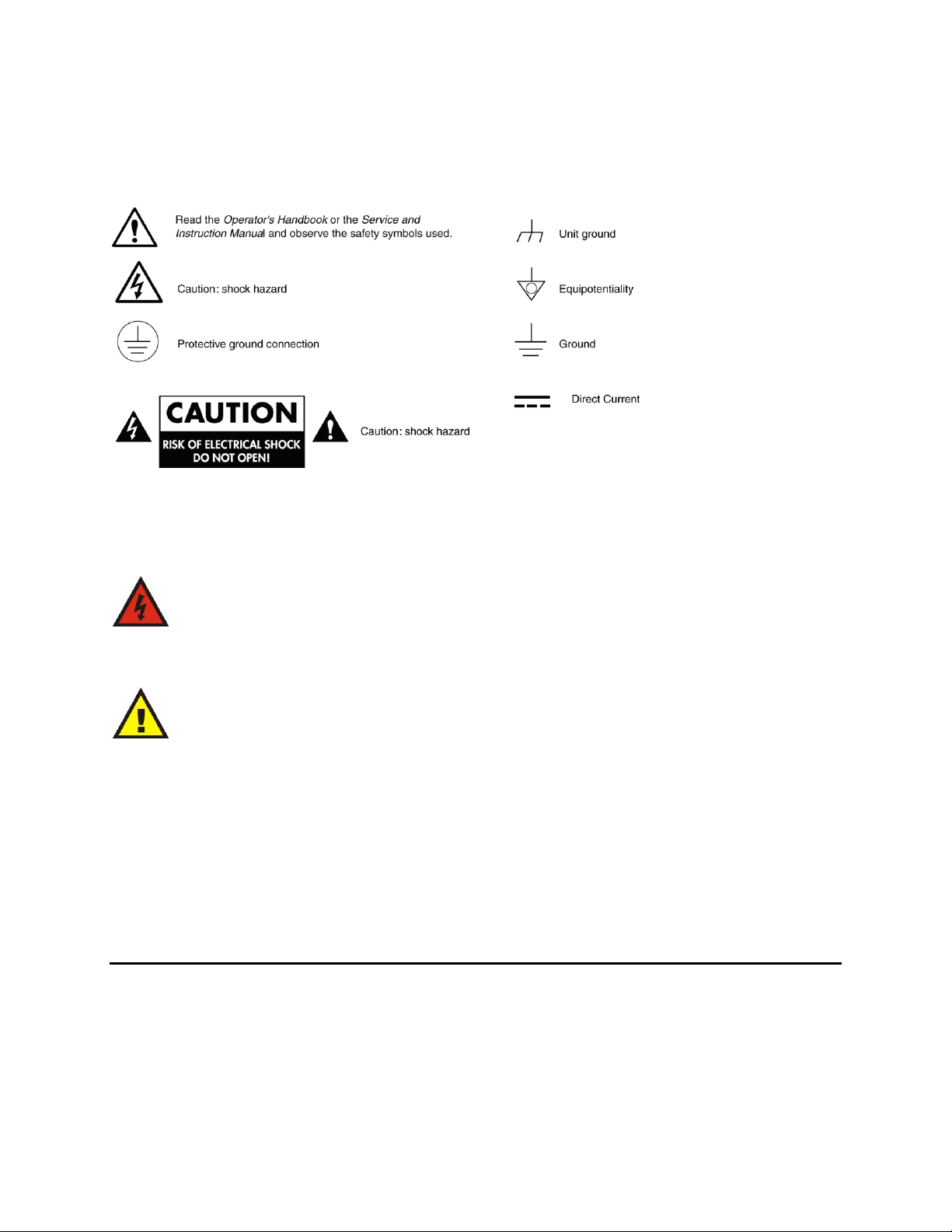
Explanation of Symbols
These symbols may appear on Imagine Communications equipment:
Figure 1: Safety Symbols that may Appear
This product manual uses the following safety terms and symbols to identify certain conditions or
practices.
WARNING
Identifies conditions or practices that can result in personal injury or loss of life — high voltage
is present. Uninsulated dangerous voltage within the product’s enclosure may be sufficient to
constitute a risk of electric shock to persons.
CAUTION
Identifies conditions or practices that can result in damage to the equipment or other property.
Important operating and maintenance (servicing) instructions are included in the literature
accompanying the product.
Certification Labels and Symbol Locations
On Imagine Communications equipment, certification labels and symbols are located on the back panel,
rear chassis sides, or bottom rear of the chassis. On smaller space-restricted units, most labels and
symbols can be found on the bottom rear of the chassis.
Directives and Compliances
This section provides information concerning Imagine Communications compliance with EU Directive
2002/95/EC and EU Directive 2002/96/EC.

CMN-91
Installation and Operation Manual About This Manual
© 2016 Imagine Communications Corp. Proprietary and Confidential. Revision D | Page 15
Restriction on Hazardous Substances (RoHS) Directive
Directive 2002 / 95 / EC — commonly known as the European Union (EU) Restriction on Hazardous
Substances (RoHS) — sets limits on the use of certain substances found in electrical and electronic
equipment. The intent of this legislation is to reduce the amount of hazardous chemicals that may leach
out of landfill sites or otherwise contaminate the environment during end-of-life recycling. The
Directive, which took effect on July 1, 2006, refers to the following hazardous substances:
Lead (Pb)
Mercury (Hg)
Cadmium (Cd)
Hexavalent Chromium (Cr-V1)
Polybrominated Biphenyls (PBB)
Polybrominated Diphenyl Ethers (PBDE)
In accordance with this EU Directive, products sold in the European Union will be fully RoHS-compliant
and "lead-free." Spare parts supplied for the repair and upgrade of equipment sold before July 1, 2006
are exempt from the legislation. Equipment that complies with the EU directive will be marked with a
RoHS-compliant symbol, as shown below.
Figure 2: RoHS Compliance Symbol
Waste from Electrical and Electronic Equipment (WEEE)
Directive
The European Union (EU) Directive 2002 / 96 / EC on Waste from Electrical and Electronic Equipment
(WEEE) deals with the collection, treatment, recovery, and recycling of electrical and electronic waste
products. The objective of the WEEE Directive is to assign the responsibility for the disposal of
associated hazardous waste to either the producers or users of these products. As of August 13, 2005,
producers or users are required to recycle electrical and electronic equipment at end of its useful life,
and must not dispose of the equipment in landfills or by using other unapproved methods. (Some EU
member states may have different deadlines.)

CMN-91
Installation and Operation Manual About This Manual
© 2016 Imagine Communications Corp. Proprietary and Confidential. Revision D | Page 16
In accordance with this EU Directive, companies selling electric or electronic devices in the EU will affix
labels indicating that such products must be properly recycled. Contact your local Sales representative
for information on returning these products for recycling. Equipment that complies with the EU directive
will be marked with a WEEE-compliant symbol, as shown below.
Figure 3: WEEE Compliance Symbol

CMN-91
Installation and Operation Manual Introduction
© 2016 Imagine Communications Corp. Proprietary and Confidential. Revision D | Page 17
Introduction
The CMN-91 compact video and audio monitoring unit is the most advanced, versatile, and intuitive
monitoring instrument available today. The CMN-91 is available for HD-SDI/SD-SDI (which can be
upgraded to 3 Gb/s capability in two SDI inputs). With 100% digital signal processing technology;
integral, high-resolution, XGA TFT color LCD display; the CMN-91 provides an accurate and stable user
customizable display of waveform, vector, gamut, audio, picture, relative timing, and alarm status
functions in full-screen views. In addition, the CMN-91 provides overlay display capabilities for vector,
waveform, and picture-in-picture (PIP) functions. Quick setup and parameter changes are possible with
direct access to display functions and screen location, 99 presets, context-sensitive shortcut menus, and
an intuitive navigation system.
The CMN-91 features extensive audio and video alarm capabilities, including peak level reporting. All
real-time signal alarms have user adjustable limits, time stamps from LTC or DVITC and an internal clock.
Remote interfaces include 10/100Base-T Ethernet and plug and-play USB port (supporting storage and
recall of presets and frame-capture transfer). The CMN-91 instruments are digital instruments with alldigital architecture; therefore, no periodic calibration is required. When a CMN-91 unit is equipped with
the optional battery mount, a user-supplied lithium ion battery can be used to maintain power in the
field.
The CMN-91 seamlessly integrates into any broadcast, post-production, camera maintenance, satellite
or cable facility, and is the ultimate choice for quality control, troubleshooting, or compliance checking
applications.
Product Features
The CMN-91 includes the following standard and optional features.
Standard Features
Two active loop-thru 3Gb/s-SDI/HD-SDI/SD-SDI video inputs with auto detection
One AES input
Passive looping external reference to support blackburst and tri-level sync
5x oversampling for enhanced audio True Peak detection
All AES and embedded audio inputs are sample rate converted to 48 kHz
Dual link (4:4:4) Y, Cb, Cr
Closed caption/teletext decode and display
Twelve-button numeric keypad
Headphone jack
Customizable function display screen location, multiple displays via overlay
Alarms with Peak Level Report
Integral high resolution XGA TFT color LCD with adjustable backlight

CMN-91
Installation and Operation Manual Introduction
© 2016 Imagine Communications Corp. Proprietary and Confidential. Revision D | Page 18
USB port for control and data transfer
XGA, High Resolution, output for 4:3 or external display (DVI-D)
Patented Video Relative Timing display
Patented Gamut display
99 user presets
Illuminated controls and indicators
Ethernet
Applicable standards: SMPTE 125M-1995, SMPTE 259M-1997, SMPTE 274M-2005, SMPTE 276M,
SMPTE 292M-1998, SMPTE 296M-2001, SMPTE 352M-2002, SMPTE 372M-2002, SMPTE 424M-2006,
SMPTE 425M-2006, SMPTE RP 178-2004, SMPTE RP 198-1998, SMPTE RP 219-2002
Optional Features
Option
Description
TVM-WRTY1
Warranty option; adds three years to the standard two-year warranty
CMN-91
Supports SD-SDI and HD-SDI video
CMN-91-S
Supports SD-SDI video
CMN-91-3GB
Supports SD-SDI, HD-SDI, and 3Gb/s-SDI video
CMN-S2H-F
Field upgrade for CMN-91-S to support HD-SDI video
CMN-S23GB-F
Field upgrade for CMN-91-S to support HD-SDI and 3Gb/s-SDI video
CMN-H23G-F
Field upgrade for CMN-91 to support 3Gb/s-SDI
CMN-AB
Anton-Bauer battery mount
CMN-AB-F
Field upgrade for an Anton-Bauer battery mount
CMN-IDX
IDX battery mount
CMN-IDX-F
Field upgrade for an IDX battery mount
DRC-3
Double rack mount case (short depth)
BLK-1
Blank panel for DRC-3
PTC-3A
Portable case with handle and tilt stand
PTC-3-CC
Padded soft case to hold PTC-3
DRC-2A
Double rack mount case (full depth)
CMN-IN-DRC2
Bracket kit for installation in a DRC-2A
RCU-CMS
Remote control unit option
Provides remote control panel for desk top applications, including Ethernet
connection software for setup of the RCU and IP addresses of connected units
Provides connections for up to 32 independent units

CMN-91
Installation and Operation Manual Introduction
© 2016 Imagine Communications Corp. Proprietary and Confidential. Revision D | Page 19
Video Formats Supported
The CMN-91 supports the following video formats:
• = Supported standards and formats
Options and Supported Video Formats
Video Formats
CMN-91-S
CMN-91
CMN-91-3GB
DVB-ASI and SMPTE-310
Analog Composite
SD-SDI
• • •
HD-SDI
• • 3 Gb/s-SDI
•
Dual Link - YCbCr 10 Bit 4:4:4
•
Dual Link – RGB and RGB+A, 10 Bit 4:4:4,
and 4:4:4:4
•
Dual Link – YCbCr and RGB, 12 Bit 4:4:4
•
3 Gb/s Formats
Format
10 bit
4:2:2
YCbCr
10 bit
4:4:4
YCbCr
10 bit
4:4:4:4
YCbCr+A
10 bit
4:4:4
RGB
10 bit
4:4:4:4
RGB+A
12 bit
4:2:2
YCbCr
12 bit
4:4:4
YCbCr
12 bit
4:4:4
RGB
1080i
1080i/60
• • • • • • •
1080i/59.94
• • • • • • •
1080i/50
• • • • • • •

CMN-91
Installation and Operation Manual Introduction
© 2016 Imagine Communications Corp. Proprietary and Confidential. Revision D | Page 20
1080p
1080p/60
•
1080p/59.94
•
1080p/50
•
1080p/30
• • • • • • •
1080p/29.97
• • • • • • •
1080p/25
• • • • • • •
1080p/24
• • • • • • •
1080p/23.98
• • • • • • •
1080psF/30
• • • • • • •
1080psF/29.97
• • • • • • •
1080psF/25
• • • • • • •
1080psF/24
• • • • • • •
1080psF/23.98
• • • • • • •
720p
720p/60
• • •
•
720p/59.94
• • •
•
720p/50
• • •
•
720p/30
• • •
•
720p/29.97
• • •
•
720p/24
• • •
•
720p/23.98
• • •
•

CMN-91
Installation and Operation Manual Introduction
© 2016 Imagine Communications Corp. Proprietary and Confidential. Revision D | Page 21
Both Level A and Level B 3 Gb/s formats are supported. When a 3 Gb/s Level A signal is detected, the
standard is shown with the letter "A" appended to the format (1080p/59.94 A). When a 3 Gb/s Level B
signal is detected, the standard is shown with the letter "B" appended to the format (1080p/59.94 B).
Dual Link Formats
Format
10 bit
4:2:2
YCbCr
10 bit
4:4:4
YCbCr
10 bit
4:4:4:4
YCbCr+A
10 bit
4:4:4
RGB
10 bit
4:4:4:4
RGB+A
12 bit
4:2:2
YCbCr
12 bit
4:4:4
YCbCr
12 bit
4:4:4
RGB
1080i
1080i/60
• • • • • • •
1080i/59.94
• • • • • • •
1080i/50
• • • • • • •
1080p
1080p/60
•
1080p/59.94
•
1080p/50
•
1080p/30
• • • • • • •
1080p/29.97
• • • • • • •
1080p/25
• • • • • • •
1080p/24
• • • • • • •
1080p/23.98
• • • • • • •
1080psF/30
• • • • • • •
1080psF/29.97
• • • • • • •
1080psF/25
• • • • • • •
1080psF/24
• • • • • • •
1080psF/23.98
• • • • • • •

CMN-91
Installation and Operation Manual Introduction
© 2016 Imagine Communications Corp. Proprietary and Confidential. Revision D | Page 22
HD Formats
10 bit
4:2:2
YCbCr
1080i
1080I/60
•
1080I/59.94
•
1080I/50
•
1080p
1080P/30
•
1080P/29.97
•
1080P/25
•
1080P/24
•
1080P/23.98
•
720p
720p/60
•
720p/59.94
•
720p/50
•
720p/30
•
720p/29.97
•
720p/24
•
720p/23.98
•
Segmented Frame
1080P/30sF
•
1080P/29.97sF
•
1080P/25sF
•
1080P/24sF
•
1080P/23.98sF
•
SD Formats
10 bit
4:2:2
YCbCr
525/59.94
•
625/50
•
CMN-91
Installation and Operation Manual Introduction
© 2016 Imagine Communications Corp. Proprietary and Confidential. Revision D | Page 23
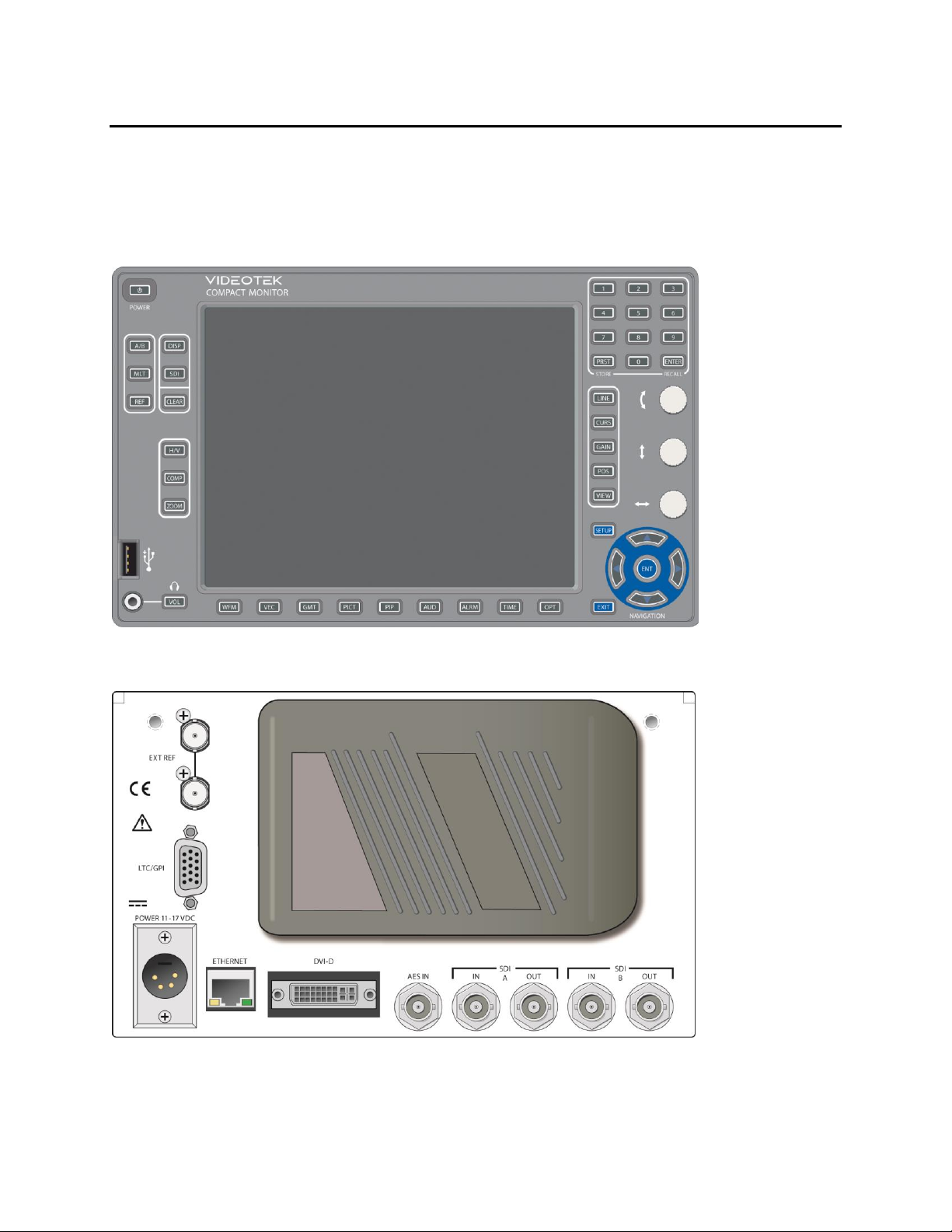
Front Panel and Back Panel Views
shows the front and back panel views of the CMN-91. See Front Panel Controls (on page 40) for
descriptions of the front panel components. See Connecting the CMN-91 (on page 32) for descriptions
of the back panel components.
Figure 4: Front View
Figure 5: Back View
The CMN-91 can also be controlled by using either a web-based control panel or an optional RCU-CMS
remote control unit. See Web-based Panel Controls (on page 42) for more information on the web-based

CMN-91
Installation and Operation Manual Introduction
© 2016 Imagine Communications Corp. Proprietary and Confidential. Revision D | Page 24
control panel. See the RCU-CMS Installation and Operation Manual for more information on the remote
control unit.
Safety
See the Operator’s Safety Summary (on page 13) for a list of important safety instructions.
Carefully observe all safety alert symbols for dangers, warnings, and cautions. They alert installers and
operators of possible dangers or important information contained in this manual.
Keep in mind, though, that warnings alone do not eliminate hazards, nor are they a substitute for safe
operating techniques and proper accident prevention measures.
CMN-91 Service and Support
For service and support, telephone the Imagine Communications Customer Service Department at
1-888-534-8246. If the problem cannot be resolved over the telephone and the instrument must be
shipped to Imagine Communications for service or repair:
Obtain a Return Authorization (RA) number from the Imagine Communications Customer Service
Department.
Attach a tag to the unit with the following information:
Your company name, address, and telephone number
The name of the contact person at your company
The RA number
The unit serial number
An explanation of the problem
To prevent shipping damage, pack the unit the same way Imagine Communications had packed it. If
possible, use the original packing materials in the original shipping container.
Ship the unit to Imagine Communications
(Address to be provided by Imagine Communications Customer Service Department)
Attn: RA xxxx (where xxxx is the RA number)
For domestic and international location and contact information, visit our Contact page
(http://www.imaginecommunications.com/how-buy/contact-us).

CMN-91
Installation and Operation Manual Installation
© 2016 Imagine Communications Corp. Proprietary and Confidential. Revision D | Page 25
Installation
Installation Procedures
Inspecting the Shipment
Before installing the CMN-91, inspect the box and the contents. Report any damage to the shipper, and
then telephone the Imagine Communications Customer Service Department (see CMN-91 Service and
Support (on page 24)).
Refer to the enclosed packing sheet for the latest list of items that are supplied with the unit.
The box contains the following:
One CMN-91 monitor/scope
One CMN-91 Installation and Operation Manual on CD
One 75 terminator
One detachable power cord
One power supply assembly
One breakout connector (for LTC/GPI)
Save the box and packing material for any future shipping requirements.
Installing the Optional Battery to Power the
CMN-91
WARNING
The battery used in this device may present a risk of fire or chemical burn if mistreated. Do
not disassemble, incinerate, or heat above the manufacturer's maximum temperature limits.
See the manufacturer's documentation for the appropriate maximum temperature limits for
your selected battery.
Replace battery with an Anton-Bauer Dionic 90 or IDX Endura-7, -7S, -10, or -10S only
(depending on mount). Use of another battery may present a risk of fire or explosion.
Dispose of used battery properly. Keep away from children. Do not disassemble and do not dispose of in
fire.
The CMN-91 can be operated by plugging in the external power supply that is shipped with every unit.
However, the unit also can be powered by a customer-supplied lithium ion battery. In order to use the
lithium ion battery, the optional battery mount must be ordered.

CMN-91
Installation and Operation Manual Installation
© 2016 Imagine Communications Corp. Proprietary and Confidential. Revision D | Page 26
CAUTION
Do not operate a CMN-91 unit with both external power and battery connected at the same
time. If external power and the battery are operating at the same time, the battery will be
discharged until it is below the voltage of the external supply.
Installing the Optional Battery Mount
WARNING
Do not puncture, damage, or discard batteries in fire. The batteries can explode, releasing
hazardous chemicals. Dispose of the batteries according to the instructions of the battery
manufacturer and in accordance with local laws.
The CMN-91 unit can use an optional lithium ion battery for remote operation.
When using the Anton-Bauer Gold Mount, customers should use an Anton Bauer Dionic 90 lithium
ion battery. Visit www.antonbauer.com/WhereToBuy for ordering information.
When using the IDX V-Mount, customers should use an IDX Endura-7, -7S, -10, or -10S battery. Visit
www.idxtek.com/dealer_locator/ for ordering information.
If the battery mount was not purchased with the unit, perform the following:
1. Remove the portable case from the CMN-91. Set all mounting hardware aside, as you will use it to
reinstall the portable case.
2. Remove the cover from the CMN-91. Set all mounting hardware aside, as you will use it to reinstall
the cover.
3. Using a flat blade screw driver, twist the slug out of the rear of the cover.
4. Acquire the battery mount and the spacer plate. Insert the rubber grommet on the battery mount
wires into the spacer plate.
5. Pass the connector housing on the end of the battery mount wires through the hole in the cover.
6. Plug the connector into the five-position header on the CMN101 board.
7. Slide the cover back onto the chassis and reinstall the screws.
8. Reinstall the portable case.
9. Mount the battery mount and spacer plate using the four screws included in the kit.
Charging the Battery
The CMN-91 does not charge the battery when using the AC adapter. See the manufacturer's
documentation for instructions on charging or recharging your selected battery.

CMN-91
Installation and Operation Manual Installation
© 2016 Imagine Communications Corp. Proprietary and Confidential. Revision D | Page 27
Rack Mounting the CMN-91
CAUTION
The CMN-91 should not be installed in a DRC-1 case. If installed in a DRC-1 case, the unit will
overheat.
When selecting the permanent mounting location for the CMN-91, make sure that the flow of air to the
ventilation holes on the top and sides of the chassis is not obstructed.
Rack mounting the CMN-91 is illustrated in for the DRC-3 rack mount case, and in for the DRC-2A double
rack mount case (for installing one or two CMN-91 units). lists the parts required to rack mount the
CMN-91 into the DRC-3 rack mount case and lists the parts required to rack mount the CMN-91 into the
DRC-2A double rack mount case.
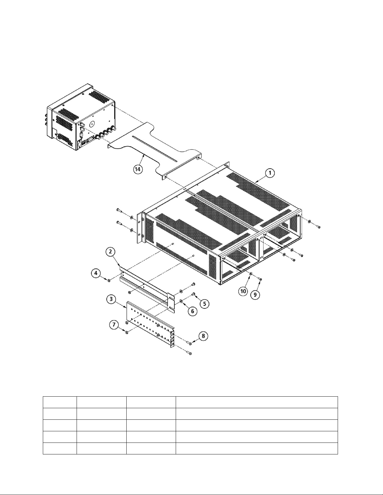
DRC-3 Rack Mount Installation
Figure 6: Mounting the CMN-91 in a Rack Using the DRC-3

CMN-91
Installation and Operation Manual Installation
© 2016 Imagine Communications Corp. Proprietary and Confidential. Revision D | Page 28
Although only one CMN-91 unit is shown, two CMN-91 units may be mounted into a DRC-3 rack case.
Parts Required to Rack Mount the CMN-91 Using the DRC-3
Key
Item Number
Qty
Description
1 - A/R
CMN-91 unit
2
866078
1
DRC-3 rack case
3
831030
4
#10-32×¾-in. Phillips head screws
4
831019
4
Nylon washer, rack mount
5
831064
4
#8-32×½-in. Phillips head screws (CMN mtg)
6
831114
4
#8 Ext. tooth lock washers
7
832125
2
Optional metal rack ears, flush mount
8
832072
2
Metal extension mount
9
832070
2
Metal extension bracket
10
831119
8
#8-32 kep nuts
11
831064
4
#8-32×½-in. Phillips head screws
12
831118
8
#10 flat washers
13
831030
4
#10-32×¾-in. Phillips head screws
14
831060
4
#10-32 kep nuts
15
832131
1
Optional metal cover plate
16
831180
4
#4-40×¼ self-tapping Phillips head screws
These instructions are for installing units without the optional rack mounting extensions. For installing
units with the optional extensions, see DRC-3 Rack Mount with Rack Extensions Installation (on page
28).
To mount the CMN-91 into a DRC-3 rack mount without rack extensions, follow these steps:
1. Slide the CMN-91 unit (ITEM 1) in the DRC-3 rack case (ITEM 2).
2. Using ¾-in. Phillips head screws (ITEM 3) and lock washers (ITEM 4), secure the CMN-91 unit to the
front of the DRC-3 rack case.
3. Using ½-in. Phillips head screws (ITEM 5) and lock washers (ITEM 6), secure the CMN-91 unit to the
back of the DRC-3 rack case.
4. If desired, install the optional cover plate:
Slide the metal cover plate (ITEM 15) into the desired side of the DRC-3 rack.
Using 4 self tapping screws (ITEM 16), secure the cover plate into the DRC-3 rack.
The installation is complete.
DRC-3 Rack Mount with Rack Extensions Installation
To install the optional flush mount rack ears (ITEM 7), first remove existing rack ears, but do not remove
the metal spacers. Using the same hardware, attach the flush mount rack ears.

CMN-91
Installation and Operation Manual Installation
© 2016 Imagine Communications Corp. Proprietary and Confidential. Revision D | Page 29
To mount the CMN-91 into a DRC-3 rack mount with rack extensions, follow these steps:
1. Install the extension bracket mounts (ITEM 8) to both sides of the DRC-3 chassis (ITEM 2) using 4
nuts (ITEM 10).
2. Install the assembled CMN-91 unit (ITEM 1) in the DRC-3 chassis (ITEM 2) using screws (ITEM 3) and
washers (ITEM 4) through the chassis front mounting ears.
3. Hold the extension bracket (ITEM 9) in place on each side of chassis, and then loosely install the kep
nuts (ITEM 10), screws, (ITEM 11), and washers (ITEM 12) into the proper holes that align with the
slots in the metal extension mount (ITEM 8).
4. Install the remaining hardware (ITEMS 12, 13, and 14) through the rack rails and the appropriate
slots in the back of the bracket (ITEM 9), and then tighten the hardware.
5. Tighten the hardware (ITEMS 10, 11, and 12) that joins the bracket pairs.
6. If desired, install the optional cover plate.
Slide the metal cover plate (ITEM 15) into the desired side of the DRC-3 rack.
Using self-tapping screws (ITEM 16), secure the cover plate into the DRC-3 rack.
The installation is complete.
CMN-91
Installation and Operation Manual Installation
© 2016 Imagine Communications Corp. Proprietary and Confidential. Revision D | Page 30
DRC-2A Rack Mount Installation
Figure 7: Mounting the CMN-91 in a Rack Using the DRC-2A
See below for information about installing the flush mount rack ears.
Parts Required to Rack Mount the CMN-91 Using the DRC-2A
Key
Item No.
Qty
Description
1
149111
1 unit
Dual rack case assembly
2
149140
2 (1 each side)
Extension bracket mount
3
149150
2 (1 each side)
Extension bracket
4
043120
4 (2 each side)
#8-32 kep nuts
 Loading...