


Delivering the Moment
Installation and Operation Manual
™
Videotek
Loudness Logger and Monitor
LLM-1770/LLM-1770-D
Revision D
Part Number P061-0010

Publication Information
© 2014 Imagine Communications Corp. Proprietary and Confidential.
Imagine Communications considers this document and its contents to be proprietary and confidential. Except for
making a reasonable number of copies for your own internal use, you may not reproduce this publication, or any
part thereof, in any form, by any method, for any purpose, or in any language other than English without the
written consent of Imagine Communications. All others uses are illegal.
This publication is designed to assist in the use of the product as it exists on the date of publication of this manual,
and may not reflect the product at the current time or an unknown time in the future. This publication does not in
any way warrant description accuracy or guarantee the use for the product to which it refers. Imagine
Communications reserves the right, without notice to make such changes in equipment, design, specifications,
components, or documentation as progress may warrant to improve the performance of the product.
Trademarks
Videotek™ is a trademark of Imagine Communications or its subsidiaries.
Microsoft® and Windows® are registered trademarks of Microsoft Corporation. All other trademarks and trade
names are the property of their respective companies.
Contact Information
Imagine Communications has office locations around the world. For locations and contact information see:
http://www.imaginecommunications.com/contact-us/
Support Contact Information
For support contact information see:
Support Contacts: http://www.imaginecommunications.com/services/technical-support/
eCustomer Portal: http://support.imaginecommunications.com
© 2014 Imagine Communications Corp. Proprietary and Confidential

Contents
About This Manual................................................................................................. 1
Intended Audience ................ .............................. ............................. ......................... .... 1
Finding Specific Information ........................................................................................ 1
Manual Information ............................... ............................. ......................... ................. 2
Revision History ......................................................................................................... 2
Writing Conventions ....... ... .... ... ... ... .... ...................................... .... ... ... ... ... ................. 2
Obtaining Documents ........ .... ...................................... .... ... ... ... .... ............................. 3
Unpacking/Shipping Information ................................................................................ 3
Unpacking a Product ................................................................................................. 3
Product Servicing ....................................................................................................... 3
Returning a Product ................................................................................................... 3
Operator’s Safety Summary ......................................................................................... 4
Ensuring Safety .......................................................................................................... 4
Explanation of Symbols .............................................................................................. 5
Certification Labels and Symbol Locations .................................................................. 5
Directives and Compliances ...................................................... .......... ......... .......... ....... 6
Restriction on Hazardous Substances (RoHS) Directive ................................................ 6
Waste from Electrical and Electronic Equipment (WEEE) Directive ............................... 6
iii
Chapter 1 Introduction.............................................................................................................. 9
Product Features ........................................................................................................... 9
Standard Features ........ ... ... .... ... ... ... ....................................... ... .... ............................. 9
Optional Features .................................................................................................... 10
Applicable Standards ....................................... ... ... ....................................... ... ... ... .. 10
Front Panel and Back Panel Views ........................................................ .....................11
Safety .................................. ....................................................... .................................. 11
LLM-1770 Service and Support .................................................................................. 12
Chapter 2 Installation............................................................................................................. 13
Installation Procedures ............................................................................................... 13
Inspecting the Shipment .......................................................................................... 13
Rack Mounting the LLM-1770 ................................................................................. 14
Connecting the LLM-1770 ................................................... ............................. ........... 16

Contents
iv
Ethernet Setup ...................................... ............. ............. ............. ............. ......... ..........17
Chapter 3 Operation..................................................................................................................19
Terms ............................................................................................................................19
Controlling the LLM-1770 ........................................................................................... 19
Front Panel Controls ...............................................................................................20
Web-Based Panel Controls ....................................... ... ... ... .... ... ... .............................22
Front Panel Selections .................................................................... ............................. 24
Selecting a Function .................... ... ... ... .... ...................................... .... ... ... ................24
Status Display ..........................................................................................................24
Bars Display .................................................................................................................26
Loudness Display ..................................... ....................................................... ............. 27
ATSC A/85 Loudness Mode ......................................................................................28
EBU R 128 Loudness Mode ......................................................................................29
ARIB TR-B32 Loudness Mode ...... ...................................... .... ... ... .............................30
Custom Loudness Mode ................ ... ... .... ... ... ... .... ...................................... ... .... ... ...31
Alarm Display ..............................................................................................................32
Meter Based Alarms .................................................................................................32
Loudness Alarms ..................... .... ...................................... .... ... ... .............................33
Dolby Alarms .............. ... ... ... ... .... ... ....................................... ... ... ... ..........................33
Time Code Alarms ...................... ...................................... .... ... ................................33
General Purpose Interface (GPI) Alarms .......................... ... .... ... ... ... ..........................33
Accessing and Navigating the Setup Menu ..............................................................34
Chapter 4 Setup Menu Functions........................................................................................35
Setup Menus and Alarm Tables .................................................................. ................ 36
Meter Mapping Setup Menu ...................................................................................... 37
Menu Selections ......................................................................................................37
Menu Selection Descriptions ....................................................................................38
Loudness Mapping Setup Menu ................................................................................38
Menu Selections ......................................................................................................38
Menu Selection Descriptions ....................................................................................39
Loudness Display Setup Menu ................................................................................... 40
Menu Selections ......................................................................................................40
Menu Selection Descriptions ....................................................................................42
Dolby Setup Menu ......................................................................................................45
Menu Selections ......................................................................................................45
Menu Selection Descriptions ....................................................................................46
Headphones Setup Menu ...........................................................................................46
Menu Selections ......................................................................................................47
Menu Selection Descriptions ....................................................................................47
Alarms Setup Menu ........................................ ...................... ....................... ................47
Clear Setup Menu 48
Menu Selections ......................................................................................................48
Menu Selection Descriptions ....................................................................................48
Unit Configuration Setup Menu .......................................... ............................. ..........48

Installation and Operation Manual
VSG-4TSG
Menu Selections ......................................... .... ... ...................................... .... ... ... ...... 48
Menu Selection Descriptions .............. ... ....................................... ... ... ... ... .... ............ 49
USB Utilities Menu Selections .................................................................................... 51
Menu Selections ......................................... .... ... ...................................... .... ... ... ...... 51
Menu Selection Descriptions .............. ... ....................................... ... ... ... ... .... ............ 51
About Menu ................................................................................................................ 53
Menu Selections ......................................... .... ... ...................................... .... ... ... ...... 53
Menu Selection Descriptions .............. ... ....................................... ... ... ... ... .... ............ 54
Chapter 5 Alarm Descriptions.............................................................................................. 57
Alarm Setup Menus .................................................................................................... 57
Meter Based Alarms Setup Menu .............................................................................. 58
Menu Selections ......................................... .... ... ...................................... .... ... ... ...... 58
Menu Selection Descriptions .............. ... ....................................... ... ... ... ... .... ............ 58
Loudness Alarm Setup Menu ..................................................................................... 59
Menu Selections ......................................... .... ... ...................................... .... ... ... ...... 59
Menu Selection Descriptions .............. ... ....................................... ... ... ... ... .... ............ 59
Dolby Alarms Setup Menu ......................................................................................... 60
Menu Selections ......................................... .... ... ...................................... .... ... ... ...... 60
Menu Selection Descriptions .............. ... ....................................... ... ... ... ... .... ............ 60
Time Code Alarms Setup Menu .................................................................................. 60
Menu Selections ......................................... .... ... ...................................... .... ... ... ...... 60
Menu Selection Descriptions .............. ... ....................................... ... ... ... ... .... ............ 61
GPI Alarms Setup Menu ........................................... ............................. ...................... 61
Menu Selections ......................................... .... ... ...................................... .... ... ... ...... 61
Menu Selection Descriptions .............. ... ....................................... ... ... ... ... .... ............ 61
v
Chapter 6 External Control.................................................................................................... 63
Browser Interface ..................................................... ................................... ................ 63
Accessing the Web-Based Control Panel ................................................................... 64
Accessing the Index of Captures .......................................................................... ...... 65
Managing User Accounts ......................................... ... ... ....................................... ... ... 66
Adding Accounts ..................... ... ....................................... ... ... .... ............................ 66
Editing Accounts .................. ... ....................................... ... ... ... .... ............................ 67
Deleting Accounts ................................................................................................... 67
Accessing the About Page ............................................. ............................................. 68
Chapter 7 Troubleshooting.................................................................................................... 71
Initial Checks ............................................................................................................... 71
Restarting .................................................................................................................... 71
Problems, Causes, and Solutions ............................................................................... 72
Chapter 8 Specifications........................................................................................................ 73

Contents
vi
Inputs ...........................................................................................................................73
Outputs ........................................................................................................................74
OLED Display ...............................................................................................................75
Communication Interfaces ................................................ .......................................... 75
Ethernet .......................................................................................................................75
Power Requirements ............................................................ ....................................... 76
Mechanical ................................................................................................................... 76
Environmental .............................................................................................................76
Standard and Optional Accessories ...........................................................................77
Appendix A Pinouts.......................................................................................................................79
LTC/GPI D-Sub Connector ......................................................... ...................................79
Ethernet RJ45 Connector ............................................................................................80
Power Connector ............................................... ....................................................... ... 80
Appendix B Log File Contents..................................................................................................81
Naming Conventions ................................................ ......................... ..........................81
File Type Contents and Samples ................................................................. ................ 82
Data File Contents ...................................................................................................82
Sample Data File ......................................................................................................82
Alarm File Contents .................................................................................................83
Sample Alarm File ....................................................................................................83
Summary File Contents ............................................................................................84
Appendix C Glossary.....................................................................................................................85
Appendix D Open Source Software Copyright Information.......................................97
FreeType License ................................................................ .......................................... 97
LibJPEG License ........................ .................................................... ................................ 97
CMU/UCD Copyright Notice .......................................................................................97
Networks Associates Technology, Inc. Copyright Notice (BSD) ................................98
Cambridge Broadband Ltd. Copyright Notice (BSD) ................................................. 98
Sun Microsystems, Inc. Copyright Notice (BSD) ........................................................ 99
Sparta, Inc. Copyright Notice (BSD) .........................................................................100
Cisco/BUPTNIC Copyright Notice (BSD) ............................................ ........................100
Fabasoft R&D Software GmbH & Co. KG Copyright Notice (BSD) ......................... 101
The GNU v2 License ........................................ ................................................... ........ 101
GNU General Public License ...................................................................................101
GNU General Public License ...................................................................................102
GNU Lesser Public License ........................................ ......................... ........................106
GNU Lesser General Public License .............................................. ... .... ... ... ... ...........106
GNU Lesser General Public License .............................................. ... .... ... ... ... ...........108

About This Manual
This manual details the features, installation proced ures, operational procedures, and
specifications of the
About This Manual provides an overview of this installation and operation manual,
describes manual conventions, and tells you where to look for specific information. This
section also gives you important information on unpacking and shipping your product.
LLM-1770 loudness logger and monitor.
1
Intended Audience
This manual is written for engineers, technicians, and operators responsible for the
installation, setup, and
/ or operation of the LLM-1770 loudness logger and monitor.
Finding Specific Information
Table P-1 shows the location of specific information in this manual.
Table P-1 Finding Specific Information in this Guide
If you are looking for Go to
Alarm descriptions Page 57
Back panel information Page 16
Browser interface Page 63
Connecting Page 16
Control panels Page 11
Customer Service information Page 12
Ethernet setup and configuration Page 17
External control Page 63
Features Page 9
Front panel information Page 11, Page 20, Page 22
Mounting the unit in a DRT-4A case Page 14
Options Page 10

About This Manual
2
Table P-1 Finding Specific Informa
If you are looking for Go to
Pinouts Page 79
Setup menus Page 35
Specifications Page 73
Troubleshooting Page 71
User accounts Page 66
Manual Information
This section provides information about the revision history of the manual, writing
conventions used for ease of understanding as well as for navigation throughout the
document, and information about obtaining other product manuals.
Revision History
Table P-2 Manual Revision History
tion in this Guide (Continued)
Edition Date Revision History
A October 2010 Initial release
B November 2010 Minor corrections to content
C December 2012 Addition of LLM-1770-D Dolby content
D June 2013 Minor corrections to content
Writing Conventions
To enhance your understanding, the authors of this manual have adhered to the following
text conventions:
Table P-3 Manual Style and Writing Conventions
Term or
Convention
Bold Indicates dialog boxes, property sheets, fields, buttons, check
Italics Indicates email addresses,
Description
oxes, list boxes, combo boxes, menus, submenus, windows, lists ,
b
and selection names
the names of books or publications, and
the first instances of new terms and specialized words that need
emphasis
CAPS Indicates a specific key on the ke
Code
> or Indicates the direction of navigation through a h ier archy of menus
yboard, such as ENTER, TAB,
CTRL, ALT, or DELETE
Indicates variables or command-line entries, such as a DOS entry or
something you type into a field
an
d windows

LLM-1770
Installation and Operation Manual
3
Table P-3 Manual Style an
Term or
Convention
hyperlink Indicates a jump to another location within the electronic
Internet address Indicates a jump to a website or URL
To perform a
rocedure
p
Obtaining Documents
The installation and operation manuals for most Harris Br oadcast BCD products are included
on your Documentation and Product Resources DVD as individual Adobe Acrobat PDF files.
Most of the software applications contained on the DVD include Online Help (electronic
documents integrated into their respective software applications). While working in the
application, you can open the Online Help and print out individual topics. The most
up-to-date documentation and software is always available on our website.
d Writing Conventions (Continued)
Description
do
cument or elsewhere
Indicates important information that helps to avoid and
troubleshoot problems
Indicates the introduction to a procedure or series of procedural
steps
Unpacking/Shipping Information
This product was carefully inspected, tested, and calibrated before shipment to ensure years
of stable and trouble free service.
Unpacking a Product
1 Check equipment for any visible damage that may have occurred during transit.
2 Confirm that you have r
3 Contact your de
4 Co
ntact the carrier if any item is damaged.
5 R
emove all packaging material from the product and its associated componen ts before you
install the unit.
Product Servicing
The LLM-1770 loudness logger and monitor is not designed f or field servicing. All har dware
upgrades, modifications, or repairs require you to return the LLM-1770 to the Customer
Service ce
Returning a Product
In the unlikely event that your product fails to operate properly, please contact Customer
Service to obtain a Return Authorization (RA) number, and then send the unit back for
servicing.
aler if any item on the packing list is missing.
nter. For more information see LLM-1770 Service and Support
eceived all items listed on the packing list.
on page 12.

About This Manual
4
Keep at least one set of original packaging, in the event that you need to return a product
for servicing. If the original packaging is not available, you can purchase replacement
packaging at a modest cost or supply your own pac kaging as lon g as it meets the fo llowing
criteria:
Withstands the weight of the product
Holds the product rigid within the packaging
Leaves at least two inches of space between the product and the container
Protects the corners of the product
Ship products back to us for servicing prepaid and, if possible, in the original packaging
rial. If the product is still within the warranty period, we will return the product prepaid
mate
after servicing. For more information see LLM-1770 Service and Support
Operator’s Safety Summary
WARNING: These instructions ar e for use by qualified personnel only. T o reduce th e
risk of electric shock, do not perform this installation or any servicing unless you
are qualified to do so. Refer all servicing to qualified service personnel.
on page 12.
Ensuring Safety
If this equipment is used in a manner not specified by the manufacturer, the protecti on
The unit should not be exposed to dripping or splashing, and no objects filled with
When the unit is to be permanently cabled, connect the protective ground conductor
Operate built in units only when they are properly fitted into the system.
For permanently cabled units without built in fuses, automatic switches, or similar
Before switching on the unit, ensure that the operating voltage set at the unit matches
Units of Protection Class I with an AC supply cable and plug that can be disconnected
provided by the equipment may be impaired.
liquids, such as vases, shall be placed on the unit.
before making any other connections.
protective facilities, the AC supply line must be fitted with fuses rated to the units.
the line voltage, if appropriate. If a different operating voltage is to be s et, use a fuse
with the appropriate rating. Refer to the Installation Instructions.
must be operated only from a power socket with protective ground contact:
Do not use an extension cable–it can render the protective ground connection
ineffective.
Do not intentionally interrupt the protect ive ground conductor.
Do not break the protective ground conductor inside or outside the unit or loosen
the protective ground connection; such actions can cause the unit to become
electrically hazardous.
Before opening the unit, isolate it from the AC supply. Then, ensure that
Adjustments, part replacements, maintenance, and repairs are carried out by
qualified personnel only.
Safety regulations and rules are observed to prevent accidents.

Only original parts are used to replace parts relevant to safety (for example, the
power on/off switches, power transformers, and fuses).
Replaceable fuses can be hazardous when live. Before replacing a fuse, disconnect the
AC power source.
Use caution when cleaning the equipment; isopropyl alcohol or similar solvents can
damage or remove the labels.
Observe any additional safety instructions specified in this manual.
Explanation of Symbols
These symbols may appear on Harris Broadcast equipment:
LLM-1770
Installation and Operation Manual
5
Figure P-1 Safety Symbols Appearing on Harris Broadcast Equipment
This product manual uses the following safety terms and symbols to identify certain
nditions or practices.
co
Table P-4 Saf
ety Terms and Symbols Appearing in the Product Manual
Symbol Description
WARNING: Identifies conditions or practices that can result in personal
injury or loss of life — high voltage is present. Uninsulated dangerous
voltage within the product’s enclosure may be sufficient to constitute a
risk of electric shock to persons.
CAUTION: Identifies conditions or practices that can result in damage
to the equipment or other property. Important operating and
maintenance (servicing) instructions are included in the literature
accompanying the product.
Certification Labels and Symbol Locations
On Harris Broadcast equipment, certification labels and symbols are located on the back
panel, rear chassis sides, or bottom rear of the chassis. On smaller space-restricted units,
most labels and symbols can be found on the bottom rear of the chassis.

About This Manual
6
Directives and Compliances
This section provides information concerning Harris Br oadcast compliance with EU Dir ective
2002/95/EC and EU Directive 2002/96/EC.
Restriction on Hazardous Substances (RoHS) Directive
Directive 2002 / 95 / EC — commonly known as the European Union (EU) Restriction on
Hazardous Substances (RoHS) — sets limits on the use of certain substances found in
electrical and electronic equipment. The intent of this legislation is to reduce the amount of
hazardous chemicals that may leach out of landfill sites or otherwise contaminate the
environment during end-of-life recycling. The Directive, which took effect on July 1, 2006,
refers to the following hazardous substances:
Lead (Pb)
Mercury (Hg)
Cadmium (Cd)
Hexavalent Chromium (Cr-V1)
Polybrominated Biphenyls (PBB)
Polybrominated Diphenyl Ethers (PBDE)
In accordance with this EU Directive, products
RoHS-compliant and “lead-free.” Spare parts supplied for the repair and upgrade of
equipment sold before July 1, 2006 are exempt from the legi
complies with the EU directive will be marked with a RoHS-compliant symbol, as shown in
Figure P-2.
sold in the European Union will be fully
slation. Equipment that
Figure P-2 RoHS Compliance Symbol
Waste from Electrical and Electronic Equipment (WEEE) Directive
The European Union (EU) Directive 2002 / 96 / EC on Waste from Electrical and Electronic
Equipment (WEEE) deals with the collection, treatment, recovery, and recycling of electrical
and electronic waste products. The objective of the WEEE Directive is to assign the
responsibility for the disposal of associated hazardous waste to either the producers or users
of these products. As of August 13, 2005, producers or users are required to recycle
electrical and electronic equipment at end of its useful life, and must not dispose of the
equipment in landfills or by using other unapproved methods. (Some EU member states
may have different deadlines.)
In accordance with this EU Directive, companies se
EU will affix labels indicating that such products must be properly recycled. Contact your
local Sales representative for information on returning these products for recycling.
Equipment that complies with the EU directive will be marked with a WEEE-compliant
symbol, as shown in Figure P-3.
lling electric or electronic devices in the

LLM-1770
Installation and Operation Manual
7
Figure P-3 WEEE Compliance Symbol

About This Manual
8

1
9
Introduction
The Videotek® LLM-1770 loudness logger and monitor is a compact audio mo nitoring t ool
that makes it easy to confirm compliance with the latest loudness requirements. Loudness
and true peak measurements are made to the ITU-R BS.1770 standard with five times
oversampling.
Included settings match EBU R 128, ARIB TR-B32, and ATSC A/85 recommendations.
Internal memory stores five days of loudness and alarm data. Logs can be exported via
Ethernet or USB. Remote control and monitoring can be performed from any web browser.
The LLM-1770 comes with four AES inputs and has options for Dolby decode and SDI
embedded from SD, HD or 3 Gb/s sources. There is a headphone jack for local confidence
monitoring. A standard LLM-1770 with the Dolby decode option installed is considered an
LLM-1770-D.
The LLM-1770 features audio alarm capabilities, including peak audio reporting. Real-time
signal alarms have user adjustable limits. Remote interfaces include 10/100Base-T Ethernet
and plug and play USB port (supporting export of log and alarm files as well as flash
updates). The
required.
The LLM-1770 seamlessly integrates into any broadcast, post-production, satellite or cable
facility, and is the ultimate choice for quality control, troubleshooting, or compliance
checking applications.
Product Features
The LLM-1770 includes the following standard and optional features.
Standard Features
Four dedicated AES inputs
One high density 15 pin sub-D connector for 1 LTC input, 1 GPO contact closure
Ethernet port for reporting data or performing unit updates
PC control using a web browser
One universal 110/220 AC adapter that provides DC voltage power input
OLED 256×64 pixel monochrome display for unit monitoring and setup
Illuminated controls and indicators
LLM-1770 has all-digital architecture; therefore, no periodic calibration is
output, and 4 GPI inputs

10
Chapter 1
Introduction
Headphone jack
USB port for data transfer and software updates
Optional Features
Table 1-1 LLM-1770 Optional Features and Descriptions
Option Description
TM-WRTY-3YR Warranty option; adds three years to the standard two-year
LLM-OPT-SDI Software keyable upgrade to activate SD-SDI, HD-SDI, and 3
LLM-OPT-SDI-F Field-upgradable software keyable upgrade to activate SD-SDI,
LLM-1770-OPT-DLB-F Field upgrade option to add Dolby decoder card to convert an
BLK-5 Blank panel for DRT-4A
arranty
w
Gb/s input
HD-
SDI, and 3 Gb/s input
LLM-1770 to an LLM
-1770-D
DRT-4A Double rack mount case
PTC-4 Desktop case with tilt
Applicable Standards
AES3-2009: AES standard for digital audio engineering - Serial Transmis sion Format for
Two-Channel Linearly Represented Digital Audio Data
ARIB TR-B32: Operational Guidelines for Loudness of Digital Television Programs
ATSC A/85: Techniques for Establishing and Maintaining Audio Loudness for Digital
Television
EBU R 128-2010: Loudness Normalisation and Permitted Maximum Level of Audi o
Signals
IEC 268-10: Sound System Equipment - Part 10: Peak Programme Level Meters
IEC 268-17: Sound System Equipment - Part 17: Standard Volume Indicators
ITU- BS. 1770: Algorithms to Measure Audio Programme Loudness and True-Peak
Audio Level
SMPTE 259M-1997: SDTV Digital Signal/Data—Serial Digital Interface
SMPTE 272M-2004: Formatting AES/EBU Audio and Auxiliary Data into Digital Video
Ancillary Data Space
SMPTE 276M: Transmission of AES/EBU Digital Audio Signals Over Coaxial Cable
SMPTE 292M-1998: 1.5 Gb/s Signal/Data Serial Interface
SMPTE 299-2009: 24-Bit Digital Audio Format for SMPTE 292 Bit-Serial Interface
SMPTE 424M-2006: 3 Gb/s Signal/Data Serial Interface
stand

Front Panel and Back Panel Views
Figure 1-1 shows the front and back panel views of the LLM-1770. See Table 3-1 on
page 20 for descriptions of the front panel components. See Table 2-2 o
descriptions of the back panel components.
Front Panel
LLM-1770
Installation and Operation Manual
n page 16 for
11
Safety
Back Panel
Figure 1-1 LLM-1770 Front and Back Panels
See the Operator’s Safety Summary on page 4 for a list of important safety instructions.
Carefully observe all safety alert symbols for
installers and operators of possible dangers or important information contained in this
manual.
Keep in mind, though, that warnings alone do not eliminate
substitute for safe operating techniques and proper accident preven tion measures.
dangers, warnings, and cautions. They alert
hazards, nor are they a

Chapter 1
12
Introduction
LLM-1770 Service and Support
For service and support, telephone the Harris Broadcast Customer Service Department at
1-888-534-8246. If the prob lem can not be resolved over the telephone and the instrument
must be shipped to
Obtain a Return Authorization (RA) number from the Harris Broadcast Customer Service
Department.
Attach a tag to the unit with the following information:
Your company name, address, and telephone number
The name of the contact person at your company
The RA number
The unit serial number
An explanation of the problem
To prevent shipping damage, pack the unit the same way Harris Broadcast had packed
it. If possible, use the original packing materials in the original shipping container.
Ship the unit to the following location:
Harris Broadcast
(Address to be provided by Harris Broadcast Customer Service Department)
Attn: RA xxxx (where xxxx is the RA number)
Email: BCDService@harris.com
Harris Broadcast for service or repair:

Installation
2
Installation Procedures
Inspecting the Shipment
Before installing the LLM-1770, inspect the box and the contents. Report any damage to
the shipper, and then telephone the Harris Broadcast Customer Service Department (see
LLM-1770 Service and Support on p
13
age 12).
Refer to the enclosed packing sheet for the latest list of items that are supplied with the
unit.
The box contains the following:
One LLM-1770
One LLM-1770 Installation and Operation Manual on CD
One detachable power cord
One power supply assembly
One breakout connector (for LTC/GPI)
Save the box and packing material for any future shipping requirements.

14
Chapter 2
Installation
Rack Mounting the LLM-1770
When selecting the permanent mounting location for the LLM-1770, make sure that the
flow of air to the ventilation holes on the top and sides of the chassis is not obstructed .
Rack mounting the LLM-1770 is illustrated in Figure 2-1 for the DRT-4A rack mount case.
Table 2-1 lists the parts required to rack mount the LLM-1770 into the DRT-4A rack mount
case.
Figure 2-1 Mounting the LLM-1770 in a Rack Using the DRT-4A
Although only one LLM-1770 unit is shown in Figure 2-1, two LLM-1770 units may be
mounted into a DRT 4 rack case.
Table 2-1 Parts for Rack Mounting the LLM-1770 Using the DRT-4A
Key Item Number Qty Description
1 - A/R LLM-1770 unit
2 P832-0113 1 DRT-4A rack tray (without rack ears)
3 832062 2 Metal rack ears (already assembled on tray)
4 831580 4 Hardware kit: 10-32 screws with washers

LLM-1770
Installation and Operation Manual
Table 2-1 Parts for Rack Mounting the LLM-1770 Using the DRT-4A (Continued)
Key Item Number Qty Description
5 831131 4 #6-32×3/8-in. Phillips head screws (CMN mounting)
6 BLK-5 1 BLK-5 optional cover assembly (ordered separately)
7 831136 4 #4-40×¼ flat head Phillips head screws
8 P832-0109 2 Metal rack ear, flush mount (optional, installed by
customer)
1 Determine if you would prefer the flush mount option. If flush mou nt is preferred, remove
the existing rack ears (ITEM 3) and replace them with ITEM 8 (supplied), using the same
screws to install the replacement rack ears.
2 If you have a BLK-5 blanking plate (ITEM 6) and are only installing one unit in the dual rack
case, follow these steps:
a Slide BLK-5 metal backet plate (ITEM 6 assembly) into desired side of DRT-4A.
b Align the bracket pems with the mounting holes in the rack tray.
c Using 4 #4-40 flat head screws (ITEM 7), secur e blank panel assembly into DRT-4A rack
tray.
3 Install the assembled unit in a rack using four 10-32 Phillips head screws and washers (ITEM
4) through the chassis front mounting ears, as shown.
4 Install your unit or units into the rack tray, securing them using the four#6-32×3/8-in.
Phillips head screws (ITEM 5) as shown.
The installation is complete.
15

Chapter 2
16
Installation
Connecting the LLM-1770
The back panel connectors are illustrated in Figure 2-2, and the function of each connector
is described in Figure 2-2.
Figure 2-2 LLM-1770 Back Panel Connectors
Table 2-2 Descr
iption of Back Panel Connectors
Key Label Description
1 PWR 11-17VDC Power connector
2 ETHERNET RJ45, female, 10/100Base-T Ethernet connector
1
1
3 AES IN AES input BNC connectors
4 SDI IN Input BNC connectors for SDI
5 SDI OUT Output BNC connectors for SDI
6 LTC/GPI 15 pin, high-density, female, D sub connector for LTC/
1
1
See Pinouts on page 79 for the connections.
GPI inpu
t/output

Ethernet Setup
LLM-1770
Installation and Operation Manual
17
The Ethernet default settings for the LLM-1770 are as follows:
IP: 192.168.0.100
Subnet Mask: 255.255.255.0
Gateway: 0.0.0.0
1 Pr
ior to performing the LLM-1770 network configuration, obtain TCP/IP addresses from the
system administrator or the Internet service provider (ISP). These addresses are a static IP
address (unless using Dynamic Host Configuration Protocol [DHCP]), a subnet mask, and an
optional gateway IP.
Be sure to record all addres ses in the spaces p
rovided below. The gateway address is not
needed unless the LLM-1770 is routed to an outside network.
LLM-1770 interface static IP address
LLM-1770 interface subnet mask
Gateway IP address
2 Id
entify a host PC to configure and test the LLM-1770.
3 Ch
oose a dedicated PC connection or network connection method:
For a dedicated PC connection, connect the host PC with a network car d to the “ENET”
connector on the back panel of the LLM-1770, using a CAT5 network cable (not
cluded). See Figure 2-3.
in
Figure 2-3 LLM-1770 Dedicated PC Connection
For a network connection, connect the network hub to the back panel of the
LLM-1770 using a CAT5 network cable
(not included). See Figure 2-4.

ETHERNET
POWER 11 - 17VDC
LTC/GPI
SDI
AES IN
OUTIN4321
LLM-1770
Ethernet
Ethernet
10Base-T or 100Base-T hub
To LAN
OPTIONAL
18
Chapter 2
Installation
Figure 2-4 LLM-1770 Network PC Connection
4 Set up
an Ethernet configuration for the LLM-1770 as follows:
a Pr
ess the SETUP button on the LLM-1770 front panel.
b Pr
ess the Up/Down arrow button to scroll to the Unit Configuration Setup menu, and
then press the ENT button to enter the submenu.
ess the Up/Down arrow button until the IP selection option is shown.
c Pr
d Pr
ess the ENT button or Left/Right arrow button to ente r the Ethernet Config selection
option.
e Sele
ct DHCP Control, and then press the ENT button, or use the right arrow to scroll
to the next selection. (Use the Up/Down arrows to change the selection.)
f Once enabled,
the obtained DHCP address can be viewed through IP IP Address
g If using DHCP:
Press the Left/Right arrow button to select DHCP.
Press the Up/Down arrow button to toggle the state to ON.
Press the ENT button.
The IP Address is retrieved from the DHCP server and placed under the
appropriate
submenu.
h If not using DHCP:
Press the Left/Right arrow button to select IP ADDRESS.
Press the Up/Down arrow button to change the value selected, and then press the
Left/Right arrow button to select the next value.
Repeat for the remainder of the IP address, subnet mask, and gateway. To avoid
conflicts, the static IP address, subnet mask, and gateway should be obtained from
the system administrator.
Press the ENT button to accept the entered valu es.
i Pr
ess the EXIT button to exit the submenu.

Operation
3
Terms The following terms are used in this section:
Loudness Range (LU): The program loudness range over the measurement period
Max TP (dBTP): The maximum true peak value detected across either the 5.1 or Aux
channels
Dialnorm: An AC-3 metadata parameter, numerically equal to the absolute value of
the DialogLevel, carried in the AC-3 bit stream
Momentary Loudness (LKFS/LUFS): Sliding rectangular window of length 400ms,
with overlapping output of 100ms
Program or Programme (LKFS/LUFS or LU): The continuous loudness average over a
period of up to 24 hours
OLED: Organic light-emitting diode
Short Term Loudness or Loudness (LKFS/LUFS or LU): The integr ated loudness
value; Integration times are mode dependent.
Target Loudness (LKFS/LUFS): The ideal loudness value
19
Controlling the LLM-1770
Pressing and holding certain buttons will activate menus for additional functionality. See
Table 3-1 for more information.
The LLM-1770 is controlled in these ways:
Quick Controls: Controls on the fr ont panel that ad just parameters that ar e frequ ently
used. See Front Panel Controls on p
controls.
Menu Settings: Shortcut menus within a function that are used to control the
parameters for the individual function .
Global Setup Menu Settings: Setup menu parameters that affect the entire unit (not
function-specific). The Setup menu is accessed by pressing the SETUP button.
Web Interface Control: A PC, using a web browser, connects to the LLM-1770 using
the Ethernet IP address.
age 20 for more information about front panel

20
Chapter 3
Operation
Front Panel Controls
The front panel controls are illustrated in Figure 3-1.
Figure 3-1 LLM-1770 Front Panel Controls
Most buttons and text are in a
low-tally (low illumination) state; under certain conditions,
however, some buttons and text reach a high-tally (high illumination) state, as described in
Table 3-1. The high and low tally illumination levels
can be set in the High Tally and Low
Tally selection options of the Unit Configuration Front Panel setup menu selection option
(see page 48).
Multiple buttons may be high tally at the same time. The last control selected is the active
control.
Table 3-1 LLM-1770 Front Panel Controls
Key Label Description
1 VOL Volume selection button; press and
release to enable
adjustment of headphone audio volume
2 — Display window
3 SETUP
4 PRG1
Setup button; press and release to access Setup mode
Press and release to exit the displayed Setup menu
Program 1 selection button; pr ess and releas e to display data
collected from the 5.1 loudness channel analysis
Press and hold to access the Program 1 setup menu
5 LOCK
6 BARS
Lock button; press and hold to lock or unlock the front panel
BARS selection button; press and release to select audio level
meters
Press and hold to access the METER MAPPING Setup menu
7 LOUD
Loudness selection button; pr ess and release to select dis play
of ITU 1770 loudness values
Press and hold to access the LOUDNESS DISPLAY Setup
menu
8 F1 Used to enable or display the SDI thumbnail
9 F2 Not implemented
*Option required for this feature to work

LLM-1770
Installation and Operation Manual
21
Table 3-1 LLM-1
770 Front Panel Controls (Continued)
Key Label Description
10 POWER
Power switch button; press and release to turn on unit
power
Press and hold to turn off unit power
11
USB port
12
Headphone jack
13 LTC PRESENT Longitudinal time code LED indicato
r; lights green when LTC
time code is present (it has a two second persistence)
14 RUN Run LED indicator; lights green when the LLM-1770 is
colle
cting loudness information
15 ALARM Alarm LED indicator; lights red when a
n alarm condition occurs
and remains red until the user clears all alarms
16 EXIT Exit selection button; press and release
to leave menu function
selections
17 Navigation Use to navigate menus and select selection options (see
page 35 for an explanation of how to operate the navigation
ms)
ite
18 PRG2
Program 2 selection button; pr ess and releas e to display data
collected from the Aux pair loudness channel analysis
Press and hold to access the Program 2 setup menu
19 RUN Run selection button; toggles the run/pause state of the unit
20 ALRM
Alarm selection button; press and release to switch to Alarm
display
Press and hold to access the Alarm Setup menus
21 STAT Status button; press and release to select the status display
22 CLR
Clear Display selection button; press and release to invoke
the clear function
If the Alarm display is showing, CLR clears the alarm
counts
If the Loudness Display is showing, CLR clears the
collected loudness information for both program 1 and
program 2
Press and hold to access the Clear Setup menu
23 F3 Not implemented

22
Chapter 3
Operation
Web-Based Panel Controls
The web-based panel controls are illustrated in Figure 3-2. See Chapter 6, External
Control o
Web-based controls are accessible from a computer that has Java™ Standard Edition
Version 6, Update 17 or later installed. (Java can be downloaded at www.java.com.)
n page 63 for information on how to access the web-based controls.
Figure 3-2 LLM-1770 Web-Based Panel Controls
Most buttons and text are in a
low-tally (grey outline) state; under certain conditions,
however, some buttons and text reach a high-tally (blue outline) state, as described in
Table 3-2. If a function is not operational, the
associated button appears greyed.
Multiple buttons may be high tally at the same time. The last control selected is the active
control.
Table 3-2 LLM-1770 Web-Based Panel Controls
Key Label Description
1 — Display window
2 SETUP
3 PRG1
Setup button; press and release to access Setup mode
Press and release to exit the displayed Setup menu
Program 1 selection button; press and release to display data
collected from the 5.1 loudness channel analysis
Press and hold to access the Program 1 setup menu
4 LOCK Lock button; press and hold to lock or unlock the fr ont panel
5 BARS
BARS selection button; press and release to select audio
level meters
Press and hold to access the METER MAPPING Setup menu
6 LOUD
Loudness selection button; press and release to select
display of ITU 1770 loudness values
Press and hold to access the LOUDNESS DISPLAY Setup
menu

Installation and Operation Manual
Table 3-2 LLM-1770 Web-Based Panel Controls (Continued)
Key Label Description
LLM-1770
23
7 CONNECTION
STATUS
Indicates whether the web-based control panel is act ive ly
connected to the
LLM-1770 unit
If the Web RCU is disconnected, reconnect by refreshing the
page using your web browser’s Refresh function; alternatively,
leave the web RCU page and select the RCU menu bar link
again
8 F1 Used to enable or display the SDI thumbnail (the thumbnail will
not be visible in the RCU display)
*Option required for this feature to work
9 F2 Not implemented
10 LTC PRESENT Longitudinal time code LED indicator; lights green when LTC
time code is present (it has a two second persistence)
11 RUN Run LED indicator; lights green when the LLM-1770 is
collecting loudness information
12 ALARM Alarm LED indicator; lights red when an alarm condition occurs
and remains red until the user clears all alarms
13 EXIT Exit selection button; press and release to leave menu function
selections
14 Navigation Use to navigate menus and select selection options (see
page 35 for an explanation of how to operate the navigation
items)
15 PRG2
Program 2 selection button; press and release to display data
collected from the Aux pair loudness channel analysis
Press and hold to access the Program 2 setup menu
16 RUN Run button; Used to toggle the run / pause state of the
loudness algorithms
17 STAT Status button; used as a quick reference of input present/
mapping indications
18 ALRM
Alarm selection button; press and release to switch to Alarm
display
Press and hold to access the Alarm Setup menus
19 CLR
Clear Display selection button; press and release to invoke
the clear function
If the Alarm display is showing, CLR will clear the alarm
counts
If the Loudness Display is showing, CLR will clear the
collected loudness information for both program 1 and
program 2
Press and hold to access the Clear Setup menu
20 F3 Not implemented

Chapter 3
24
Operation
Front Panel Selections
The LLM-1770 unit shows data on the display screen. It displays actual and target loudness
levels. It also displays audio level bars using the true peak ballistic.
An illustration of the display is shown in Figure 3-1 and Figure 3-2. The display varies,
pending on the choice of display mode.
de
Selecting a Function
To directly select specific functions for the display
Press the appropriate function button. Specific functions include Lock; Program 1 and
Pr
ogram 2; Run; Loudness; BARS; Alarms; Status; and F1.
When a button is pressed that cannot be used with a selected function, the message
FUNCTIO
To lock or unlock a front panel
N NOT ALLOWED briefly appears over the center of the display.
Press and hold the Lock button.
To start collecting loudness samples
Press the Run button.
To stop collecting loudness samples
Press the Ru
run is active the Run button LED is high talley and the Run LED indicator is lit green.
To view a loudness channel collection display
To clear the display
If the Loudness Display is sh
information for both program 1 and program 2.
n button a second time. When paused, the Run button LED is low talley. When
Press the PRG1 button to select 5.1 channels display.
Press the PRG2 button to select stereo pair display.
Press the CLR button to clear the display.
owing, pressing the CLR button clears the collected loudness
Status Display
To view status
Press the Sta
shown in Figure 3-3. Use the Down arrow to access the second
arrow to access the first status page from the second status page.
tus button to view program status. Status information will be displayed as
status page. Use the Up
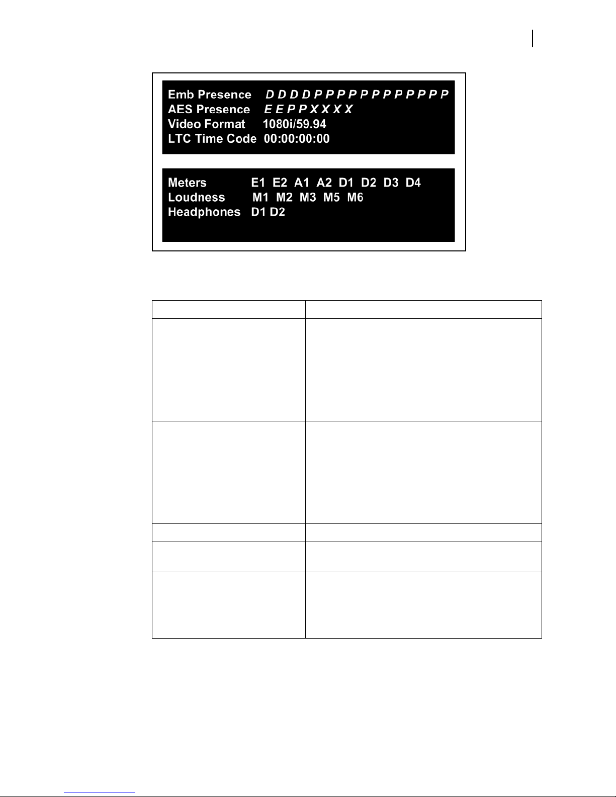
Figure 3-3 Status Display
LLM-1770
Installation and Operation Manual
25
Table 3-3 Status Information D
escriptions
Field Name Description
Emb Presence Graphical depiction of which embedded audio
channe
P indicates the presence of PCM audio
D indicates the presence of Dolby D or Dolby D+
ls are present
encoded audio
E indicates the presence of Dolby E encoded audio
An X mark indicates embedded audio channel is
not present
AES Presence Graphical depiction of which AES audio channels are
pr
esent
P indicates the presence of PCM audio
D indicates the presence of Dolby D or Dolby D+
encoded audio
E indicates the presence of Dolby E audio
An X mark indicates AES audio channel is not
present
Video Format Current video input format
LTC Time code Current LTC time code value disp
layed in hours,
minutes, seconds, and frames
Meters Current meter mapping
E = Embedded
A = AES
D = Dolby Decoder
# = Channel number of source

26
Chapter 3
Operation
Bars Display
Table 3-3 Status Information D
escriptions
Field Name Description
Loudness Current loudness mapping
M= Meter indicator
# = Meter number of source
Loudness mapping is meter -based, not
input-based.
Headphone Current headphone mapping (headphone mapping is
input based, not meter based)
E = Embedded
A = AES
D = Dolby Decoder
# = Channel number for headphones
The Bars display shows up to eight true peak audio meters, grouped as 5.1 and an Aux or
stereo pair. The first six meters represent Program 1 data and the remaining two meters
represent Program 2. The large text represents the short-term loudness and the vertical bar
represents the momentary loudness.
The LLM-1770 supports up to eight individual audio meters. Meter displays
are associated
or mapped to physical inputs through menu options.
To display the bargraph meters
Press and release the BARS button. The Bars display is shown in Figure 3-4.
The dashed line represents the target loudness as entered through the menu
system
Figure 3-4 Bars Display
To access the Meter Mapping setup menu
Press and hold the BAR
S button; or, press the SETUP button, and then use the navigation
buttons to scroll through the menu selections.
Meter mapping allows any input source to be
mapped to any meter. The meter names are
fixed and are assigned to meters 1 through 8 from left to right; that is, L = meter 1,
R = meter 2.
To leave the Meter Mapping setup menu
Press the SE
TUP or the EXIT button.

Loudness Display
The Loudness display shows one of four modes: ATSC A/85, EBU R 128, ARIB TR-B32, or
Custom. These modes are selected in the Loudness Display setup menu. Illustrations of the
displays for Loudness mode are shown in
To access the loudness display
Press and release the LOUD function button.
To access the Loudness Display setup menu
Press and hold the LOUD button; or, press the SETUP button, and then use the na vig at ion
buttons to scroll through the menu selections.
To leave the Loudness Display setup menu
Press the SETUP or the EXIT button.
LLM-1770
Installation and Operation Manual
Figure 3-5, Figure 3-6, and Figure 3-8.
27

28
Chapter 3
Operation
ATSC A/85 Loudness Mode
The display in ATSC A/85 loudness mode shows selections that follow ATSC recommended
practice A/85. Up to four measurements (as controlled from the menus) can be displayed.
Figure 3-5 Display in ATSC A/85 Loudness Mode
Table 3-4 A
TSC A/85 Display Information Descriptions
Key Description
1 Maximum true peak (in dBTP)
2 Channel (Left, Right, Center, Left Surround, Right Surround)
where maximum
true peak was detected
3 Program loudness (in LKFS or LU)
4 Integrated loudness (in LKFS or LU)
5 Momentary loudness (represented as 0 to -70 LKFS)
6 Dialnorm value as extracted from Dolby metadata. The Dialnorm
Sou
rce is selectable in the Dolby Setup menu and can be derived
from VANC or from the Dolby Decoder input. If the Dolby option
is not installed, the Dialnorm Source defaults to Dolby E VANC.
"- -" Indicates that no dialnorm value was found.

EBU R 128 Loudness Mode
The display in EBU R 128 loudness mode shows selections that follow EBU r ecommendation
R 128.
Figure 3-6 Display in EBU R 128 Loudness Mode
LLM-1770
Installation and Operation Manual
29
Table 3-5 EBU R 12
8 Display Information Descriptions
Key Description
1 Maximum true peak (in dBTP)
2 Channel (Left, Right, Center, Left Surround, Right Surround)
where maximum
true peak was detected
3 Programme loudness (in LUFS or LU)
4 Integrated loudness (in LUFS or LU)
5 Momentary loudness (represented as 0 to -70 LUFS)
6 Loudness range (in LU)

30
Chapter 3
Operation
ARIB TR-B32 Loudness Mode
The display in EBU R 128 loudness mode shows selections that follow EBU r ecommendation
R 128.
Figure 3-7 Display in EBU R 128 Loudness Mode
Table 3-6 EBU R 12
8 Display Information Descriptions
Key Description
1 Maximum true peak (in dBTP)
2 Channel (Left, Right, Center, Left Surround, Right Surround)
where maximum
true peak was detected
3 Programme loudness (in LKFS or LU)
4 Integrated loudness (in LKFS or LU)
5 Momentary loudness (represented as 0 to -70 LKFS)
6 Loudness range (in LU)

Custom Loudness Mode
The display in custom loudness mode shows selections that match a user’s in-house
standards.
Figure 3-8 Display in Custom Loudness Mode
LLM-1770
Installation and Operation Manual
31
Table 3-7 Cus
tom Display Information Descriptions
Key Description
1 Maximum true peak (in dBTP)
2 Channel (Left, Right, Center, Left Surround, Right Surround) where
maximu
m true peak was detected
3 Program loudness (in LKFS or LU)
If the absolute gating value is changed and the CLR button is
pressed, the program loudness will default to the absolute gate
value.
4 Integrated loudness (in LKFS or LU)
5 Momentary loudness (represented as 0 to -70 LKFS)
6 Loudness range (in LU)

Chapter 3
32
Operation
Alarm Display
To view alarms
Press the ALRM
shown in Figure 3-9.
Figure 3-9 Alarms Display
button to view alarm status. Alarm status information is displayed as
The alarm display informs the user that an alar
groups: meter based, loudness, time code, or GPI. Each group can support a maximum of
9999 events before the counter stops incrementing.
me Since Reset counter indicates how much time has passed since the CLR button
The Ti
was last pressed. This value stops incrementing after five days, and is indicated by the
LLM-1770 unit displaying the message > 5 Days.
To access the alarm display
Press and release the ALRM function button.
To access the Alarm Setup menu
Press and hold the AL
To clear the display
Press the CLR button to clear the display.
To clear the alarm counts
Press the CL
For information on individual alarms, see Chapter 5, Alarm Description
R button to clear the alarm counts.
RM function button.
m has occurred in one of four possible
s.
Meter Based Alarms
Meter-based alarms can be set for each individual meter’s peak audio, loss of sound, digital
clip, and digital mute. Default values are mode dependent (i.e., ATSC A/85, EBU R 128,
ARIB TR-B32, or custom). Parameters are retained separately for each mode.
To access the Meter Based Alarms Setup menu
Press and hold the AL
buttons to scroll throug h the menu selections and to select the Meter Based Alarm
parameters.
For more information on the global Meter Based Alarms Setup menu, see page 58.
RM button to access the Alarms Setup menu. Use the navigation

Loudness Alarms
Loudness alarms can be set for when the loudness level is higher than the target value p lus
the range above the desired loudness level, or when the loudness level is lower than target
value plus the range below the desired loudness level. The default alarm parameter
selections depend on the Loudness Mode selection.
To access the Loudness Alarms Setup menu
Press and hold the ALRM button to access the Alarms Setup menu. Use the navigat ion
buttons to scroll throug h the menu selection s and to select the Loudness Alarm parameters.
For more information on the global Loudness Alarms Setup menu, see page 59.
Dolby Alarms
To access the Alarms Setup menu
Press and hold the ALRM button to access the Alarms Setup menu. Use the navigat ion
buttons to scroll throug h the menu selections and to select the Dolby Alarms menu
selections.
LLM-1770
Installation and Operation Manual
33
To show the available Dolby Alarm menu selections
Press the ENT navigation button.
For more information on the global Dolby Alarms Setup menu, see page 60.
Time Code Alarms
Time code alarm indicates a loss of the LTC input in excess of the duration setting.
To access the Time Code Alarms Setup menu
Press and hold the ALRM button to access the Alarms Setup menu. Use the navigat ion
buttons to scroll throug h the menu selections and to select the Time Code Alarm
parameters.
For more information on the global Time Code Alarms Setup menu, see page 60.
General Purpose Interface (GPI) Alarms
The input GPIs have selectable functions. There are selectable functions to allow external
control of the unit or to show an onscreen alarm. Up to four general purpose interface
alarms can be enabled.
To access the GPI Alarms Setup menu
Press and hold the ALRM button.Use the navigation buttons to scroll through the menu
selections and to select the GPI Alarm parameters
For more information on the global GPI Alarms Setup menu, see page 61.

Chapter 3
34
Operation
Accessing and Navigating the Setup Menu
To access the global Setup menu
Press the SETUP button.
The Setup menu selections are displayed as shown in Figure 3-10.
Figure 3-10 Setup Display
Table 3-8 Se
tup Menu Details
Key Description
1 Up/Down directional marker (controlled by the Up/
wn navigation buttons)
Do
2 Main menu name
3 Submenu level number
4 Submenu number
5 Number of submenus under main menu item
6 Submenu name
7 Left/Right directional marker
(controlled by the Left/
Right navigation buttons)
To directly access specif
ic function setup menus
Press and hold the corresponding function butt on.
To display the pertinent Setup menu
Press and hold the function button or press the Set
up button and then navigate through
the menu selections.
To navigate the Setup menu
Use the navigation buttons. The navigat
For more information on the global Setup menu, see Chapter 4, Setu
ion buttons are described in Table 4-1 on page 35.
p Menu Functions.

4
Setup Menu Functions
The setup position navigation buttons are described in Table 4-1. See Figure 3-1 on
page 20 for the location of these buttons.
To access the global Setup menu
Press the SE
To navigate the Setup menu
Use the SE
selection will be indicated by a high talley navigation button.
TUP button.
TUP, UP, DOWN, LEFT, RIGHT, ENT, and EXIT buttons. The available button
35
Table 4-1 Se
Button Function
tup Button Functions
Press to exit the Setup menu.
Press to enter or exit the Setup menu.
Press to select a menu item, or open a menu or submenu.
Press to move up in a menu or submenu tree.
Press to move right to the next submenu.
Press to move out of a submenu.
Press to move down in a menu or submenu.

Chapter 4
36
Setup Menu Functions
Setup Menus and Alarm Tables
The following tables make up the global setup menu. An asterisk (*) is shown next to the
default menu selections. The Setup menu items are listed in Table 4-2 with their
rresponding Table and Description location pages.
co
Table 4-2 Se
tup Menu Tables
Selection Page
Meter Mapping Page 37
Loudness Mapping Page 38
Loudness Display Page 40
Dolby Setup Page 45
Headphones Page 47
Alarms Alarm setup tables and corresponding
de
scriptions appear in Chapter 5.
Clear Page 48
Unit Configuration Page 48
USB Utilities Page 51
About Page 53

Meter Mapping Setup Menu
The Meter Mapping setup menu enables mapping of audio meters to specific audio
channels.
Menu Selections
Table 4-3 Meter Mapping Setup Menu
Selection Option Selection Option
Meter 1 Embedded 1 •• 16
Meter 2 Embedded 1 •• 16
AES 1 •• 8
Dolby 1 •• 10
Mute
AES 1 •• 8
Installation and Operation Manual
1
1
LLM-1770
37
Dolby 1 •• 10
Mute
Meter 3 Embedded 1 •• 16
AES 1 •• 8
Dolby 1 •• 10
Mute
Meter 4 Embedded 1 •• 16
AES 1 •• 8
Dolby 1 •• 10
Mute
Meter 5 Embedded 1 •• 16
AES 1 •• 8
Dolby 1 •• 10
Mute
Meter 6 Embedded 1 •• 16
AES 1 •• 8
Dolby 1 •• 10
1
1
1
1
Meter 7 Embedded 1 •• 16
Mute
1
AES 1 •• 8
Dolby 1 •• 10
Mute

Chapter 4
38
Setup Menu Functions
Table 4-3 Meter Mapp
ing Setup Menu (Continued)
Selection Option Selection Option
Meter 8 Embedded 1 •• 16
Menu Selection Descriptions
Meter 1 •• Meter 8: Each audio meter selection may be mapped to AES channel
1 to 8, embedded audio channel 1 to 16
Loudness Mapping Setup Menu
The Loudness Mapping setup menu enables mapping of specific audio meters to loudness
channels.
AES 1 •• 8
Dolby 1 •• 10
Mute
1
1
, or set to Mute.
Menu Selections
Table 4-4 Loudness Mapping Setup Menu
Selection Option Selection Option Selection Option
Program 1 Left Disabled
Program 2 Aux 1 Disabled
Meter 1 •• Meter 8
Right Disabled
Meter 1 •• Meter 8
Center Disabled
Meter 1 •• Meter 8
Left Surround Disabled
Meter 1 •• Meter 8
Right Surround Disabled
Meter 1 •• Meter 8
Meter 1 •• Meter 8
Aux 2 Disabled
Meter 1 •• Meter 8
1
Embedded audio is only available if the SDI option is installed.

Menu Selection Descriptions
Program 1: This selection enables the selection of loudness channels in 5.1 surround
audio.
Left: This selection enables the selection of the Left loudness channel. The
selection may be disabled, or mapped to audio meter selection 1 to 8.
Right: This selection enables the selection of the Right loudness channel. The
selection may be disabled, or mapped to audio meter selection 1 to 8.
Center: This selection enables the selection of the Center loudness channel. The
selection may be disabled, or mapped to audio meter selection 1 to 8.
Left Surround: This selection enables the selection of the Left Surround loudness
channel. The selection may be disabled, or mapped to audio meter selection 1 to 8.
Right Surround: This selection enables the selection of the Right Surround
loudness channel. The selection may be disabled, or mapped to audio meter
selection 1 to 8.
Program 2: This selection enables the selection of loudness channels in stereo pairs.
Aux 1: This selection enables the selection of the Aux 1 loudness channel. The
selection may be disabled, or mapped to audio meter selections 1 to 8.
Aux 2: This selection enables the selection of the Aux 2loudness channel. The
selection may be disabled, or mapped to audio meter selections 1 to 8.
LLM-1770
Installation and Operation Manual
39

Chapter 4
40
Setup Menu Functions
Loudness Display Setup Menu
The Loudness Display setup menu is used to set the target loudness mode and level, as well
as integration and hold times.
Menu Selections
Table 4-5 Loudness Display Setup Menu
Selection Option Selection Option Selection Option Selection Option
Mode ATSC A/85
EBU R 128
ARIB TR-B32
Custom
Units LU
LKFS/LUFS
ATSC A/85 Displays
1
Program
ATSC A/85 Setup
Loudness
Max True Peak
Dialnorm
1
Program Use Relative Gating On
Off*
Relative Gating Value -10 to -6 Rel (-10 Rel*)
Loudness Integration 1 Second to 60 Seconds (10
Seconds*)
Max Hold Time 1 Second to 60 Seconds
Infinite*
Range Relative Gating Active
Relative Gating Value -20 Rel (Fixed)
Target Loudness Level -31 LKFS to -1 LKFS (-24
LKFS*)
High Level Above 0 LU to 10 LU (2 LU*)
Low Level Below 0 LU to 10 LU (2 LU*)
Absolute Gating -70 LKFS* to -50 LKFS
Dolby VANC SDID 1*to 9
Dolby Program 1*to 8
EBU R 128 Displays
1
Programme
Short Term
Max True Peak
Range

LLM-1770
Installation and Operation Manual
Table 4-5 Loudness Display Setup Menu (Continued)
Selection Option Selection Option Selection Option Selection Option
EBU R 128 Setup
1
Programme Relative Gating Active
Relative Gating Value -10 Rel (Fixed)
Short Term Integration 3 Seconds (Fixed)
Max Hold Time 1 Second to 60 Seconds
Infinite*
Range Relative Gating Active
Relative Gating Value -20 Rel (Fixed)
Target Loudness Level -23 LUFS (Fixed)
High Level Above 0 LU to 10 LU (1 LU*)
Low Level Below 0 LU to 10 LU (1 LU*)
Absolute Gating -70 LKFS (Fixed)
Arib TR-B32 Displa ys
1
Program
41
Arib TR-B32 Setup
Custom Displays
1
Short Term
Max True Peak
Range
1
Program Relative Gating Active
Relative Gating Value -10 (Fixed)
Short term Integration 3 seconds (Fixed)
Max hold time 1 Second to 60 Seconds
Infinite*
Range Relative Gating Active
Relative Gating Value -20 (Fixed)
Target Loudness Level -24LKFS (Fixed)
High level Above 0 LU to 10 LU (1 LU*)
Low level below 0 LU to 10 LU (1 LU*)
Absolute gating -70 (Fixed)
Program
Short Term
Max True Peak
Range

Chapter 4
42
Setup Menu Functions
Table 4-5 Loudness Display Setup Menu (Continued)
Selection Option Selection Option Selection Option Selection Option
Custom Setup
1
Program Use Relative Gating On*
Off
Relative Gating Value -10 to -6 Rel (-10 Rel*)
Loudness Integration
1 Second to 60 Seconds (3
Seconds*)
Max hold time 1 Second to 60 Seconds
Infinite*
Range Use Relative Gating On
Off
Relative Gating Value -22 to -18 Rel (-20 Rel*)
Target Loudness Level -31 to -1 LKFS (-23 LKFS*)
High Level Above 0 to 10 LU (1 LU*)
Low Level Below 0 to 10 LU (1 LU*)
Absolute Gating
1
This menu selection is dynamic and is affected by the particular mode selection. Depending on the selected mode (ATSC A/85, EBU R 128, ARIB TR-B32,
or Custom), only one of the selected mode’s setup and displays menus will be shown as a menu selection. When you are in a specific mode you can only
adjust the parameters associated with that particular mode. In addition, When you change a loudness mode’s parameter, the High Level Above and Low
Level Below target alarm parameters change also.
-70* to -50 LKFS
Menu Selection Descriptions
Mode: This selection is used to select the desired display mode.
ATSC A/85: This selection allows the user to select a display mode that follows
ATSC recommended practice A/85.
EBU R 128: This selection allows the user to select a display mode that follows EBU
recommendation R 128.
ARIB TR-B32: This selection allows the user to select a display mode that follows
ARIB standard TR-B32.
Custom: This selection allows the user to select a display group that matches the
user’s in-house standards.
Units: This selection is used to determine the type of scale that appears on the
Loudness display.
LKFS/LUFS: This selection allows the user to select Loudness K-weighted Full Scale.
LU: This selection allows the user to select Loudness Units.
The ATSC A/85 Display and Setup parameters are shown only when the Mode parameter
“ATSC A/85” is selected.
A TSC A/85 Display: This selection allows the user to select a display mode that follows
ATSC recommended practice A/85. Selections are Program, Loudness Integration Time,
Maximum True Peak, and Range.
ATSC A/85 Setup: This selection allows the user to set up ATSC A/85 display
information as chosen in the ATSC A/85 Display parameter.

LLM-1770
Installation and Operation Manual
Program: This selection can be set up to enable the use of relative gating. The
default setting for relative gating is Off (not enabled).
If relative gating is enabled, the Relative Ga
ting selection allows enabling of relative
gating setting, from -10 to -6. The default setting is -10.
Loudness Integration Time: This selection is used to set the integration time for
computing the loudness values. Selections range from 0 seconds to 60 seconds.
The default selection is 10 seconds.
Max Hold Time: This selection is used to set the maximum true peak hold time.
Selections are 1 to 60 seconds and Infinite. The default selection is Infinite.
Range: This selection is used to activate the relative gating range. If relative gating
is active, the Relative Gating range selection is fixed at -20.
Target Loudness: This selection is used to set the target value for the desired
loudness level.
Level selections range from -31 LKFS to -1 LKFS The default selection is -24
LKFS.
The High Level Above target selection sets the range of allowable values
above the target value for the desired loudness level. Selections range from 0
LU to 10 LU. The default setting is 2 LU.
The Low Level Below target selection sets the range of allowable values
below the target value for the desired loudness level. Selections range from 0
LU to 10 LU. The default setting is 2 LU.
Absolute Gating: This selection is used to select the threshold for absolute gating.
Absolute gating settings range from -70 LKFS to -50 LKFS. The default setting is
-70 LKFS.
Dolby VANC SDID: This selection is used to select the SDID (1-9) associated with
the Dolby VANC Metadata DID 0x45.
Dolby Program: Used to select the program source (1-8) for the Dolby Dialnorm
value.
43
The EBU R 128 Display and Setup parameters are shown only when the Mode parameter
“EBU R 128” is selected.
EBU R 128 Display: This selection allows the user to select a display group that follows
EBU recommendation R 128. Selections are Programme, Short Term Integration,
Maximum True Peak, and Range.
EBU R 128 Setup: This selection allows the user to set up EBU R 128 display
information as chosen in the EBU R 128 Display parameter.
Programme: This selection is READ ONLY and shows that the gating is active and
that the Relative Gating selection is fixed at -10.
Short Term Integration: This selection is READ ONLY and shows the integration
time for computing the loudness values. The Short Term Integration time selection
is fixed at 3 seconds.
Max Hold Time: This selection is used to set the maximum true peak hold time.
Selections are 1 to 60 seconds and Infinite. The default selection is Infinite.
Range: This selection is READ ONL Y and shows that the relative gating is active and
that the Relative Gating range selection is fixed at -20.
Target Loudness: This selection is used to set the target value for the desired
loudness level.
The Level selection is fixed at -23 LUFS.
The High Level Above target selection sets the range of allowable values
above the target value for the desired loudness level. Selections range from 0
LU to 10 LU. The default setting is 1 LU.

Chapter 4
44
Setup Menu Functions
The Low Level Below target selection sets the range of allowable values
below the target value for the desired loudness level. Selections range from 0
LU to 10 LU. The default setting is 1 LU.
Absolute Gating: This selection is READ ONLY and shows that the Absolute Gating
setting is fixed at -70 LKFS..
The ARIB TR-B32 Display and Setup parameters are shown only when the Mode parameter
“ARIB TR-B32” is selected.
ARIB TR-B32 Display: This selection allows the user to select a display group that
follows ARIB recommendation TR-B32. Selections are Programme, Short Te rm
Integration, Maximum True Peak, and Range.
ARIB TR-B32 Setup: This selection allows the user to set up ARIB-TR-B32 display
information as chosen in the ARIB-TR-B32 Display parameter.
Programme: This selection is READ ONLY and shows that the gating is active and
that the Relative Gating selection is fixed at -10.
Short Term Integration: This selection is READ ONLY and shows the integration
time for computing the loudness values. The Short Term Integration time selection
is fixed at 3 seconds.
Max Hold Time: This selection is used to set the maximum true peak hold time.
Selections are 1 to 60 seconds and Infinite. The default selection is Infinite.
Range: This selection is READ ONL Y and shows that the relative gating is active and
that the Relative Gating range selection is fixed at -20.
Target Loudness: This selection is used to set the target value for the desired
loudness level.
The Level selection is fixed at -24 LUFS.
The High Level Above target selection sets the range of allowable values
above the target value for the desired loudness level. Selections range from 0
LU to 10 LU. The default setting is 1 LU.
The Low Level Below target selection sets the range of allowable values
below the target value for the desired loudness level. Selections range from 0
LU to 10 LU. The default setting is 1 LU.
Absolute Gating: This selection is READ ONLY and shows that the Absolute Gating
setting is fixed at -70 LKFS.
The Custom Display and Setup parameters are shown only when the Mode parameter
“Custom” is selected.
Custom Display: This selection allows the user to select a display group that matches
the user’s in-house standards. Selections are Program, Short Term, Maximum T rue Peak,
and Range.
Custom Setup: This selection allows the user to set up Custom parameters.
Program: This selection can be set up to enable the use of relative gating. The
default setting for relative gating is On (enabled).
If relative gating is enabled, the Relative Ga
gating setting, from -10 LU to -6 LU. The default setting is -10 LU.
Loudness Integration Time: This selection is used to set the integration time for
computing the loudness values. Selections range from 0 seconds to 60 seconds.
The default selection is 3 seconds.
Max Hold Time: This selection is used to set the maximum true peak hold time.
Selections are 1 to 60 seconds and Infinite. The default selection is Infinite.
ting selection allows enabling of relative
LLM-1770
Installation and Operation Manual
Range: This selection is used to activate the relative gating. If relative gating is
active, the Relative Gating Value selection ranges from -22 LU to -18 LU. The
default setting is -20 LU.
Target Loudness: This selection is used to set the target value for the desired
loudness level.
Level selections range from -31 LKFS to -1 LKFS The default selection is -23
LKFS.
The High Level Above target selection sets the range of allowable values
above the target value for the desired loudness level. Selections range from 0
LU to 10 LU. The default setting is 1 LU.
The Low Level Below target selection sets the range of allowable values
below the target value for the desired loudness level. Selections range from 0
LU to 10 LU. The default setting is 1 LU.
Absolute Gating: This selection can be set up to enable the use of absolute gating.
Absolute gating settings range from -70 LKFS to -50 LKFS. The default setting is -70
LKFS.
45
Dolby Setup Menu
The Dolby setup menu is used to configure the Dolby decoder option if installed .
Menu Selections
Table 4-6 Dolby Setup Menu
Selection Option Selection Option Selection Option
Dialnorm Source VANC
Dolby Decoder *
Input Embedded Pair 1 to 8
AES Pair 1 to 4
Dolby Input Format Autodetect *
Dolby E Only
Dolby D Only
AES Channel Select Channel 1,2
Downmix Select Program Select Pgm 1 to 8
Lt/Rt *
Lo/Ro
Mono
Mute
Downmix DRC Mode Line *
RF

Chapter 4
46
Setup Menu Functions
Table 4-6 Dolby Setup Menu (Continued)
Selection Option Selection Option Selection Option
Dolby D DRC Line
RF
Custom
Bypass *
Dolby D Listen Mode Full *
EX
3 Stereo
Phantom
Stereo
Mono
Pro Logic
Dolby E Dialnorm Disable *
All Pgm Enabled
Pgm 1 Enabled
Menu Selection Descriptions
Metadata Source: This selection chooses whether Dolby Metadata is extracted from
VANC or from the decoded channel.
Input: This selection is used to choose the Dolby decoder input. Options include
Embedded Pair 1 to 8, and AES Pair 1 to 4. The input defaults to Embedded Pair 1.
Dolby Input Format: This selection is used to choose between Autodetect (default),
Dolby E Only, and Dolby D Only.
Pulldown Mode: This selection activates pulldown mode.
AES Channel Select: This selection is used to choose Channel 1 or Channe l.
Downmix Select: This selection is used to choose between Program Select (with
further options of Pgm 1 (default) to 8, Lt/Rt (Default), Lo/Ro, Mono, and Mute.
Downmix DRC Mode: This selection chooses between Line (default) and RF.
Dolby D DRC Mode: This selection is used to select between Line, RF, Custom, and
Bypass (default).
Dolby D Listen Mode: This selection is used to choose between Full (default) , EX, 3
Stereo, Phantom, Stereo, Mono.
Pro Logic: This selection is used to activate or deactivate pro logic.
Dolby E Dialnorm: This selection is used to choose between Disable (default), All Pgm
Enabled, Pgm 1 Enabled.
Headphones Setup Menu
The Headphones setup menu is used to enable the headphone or internal speaker settings.

Menu Selections
Table 4-7 Headphones Setup Menu
Selection Option Selection Option
Left Source Mute
Right Source Mute
AES 1 •• 8
Embedded 1 •• 16
Dolby 1 •• 8
Dolby Downmix L
Dolby Downmix R
AES 1 •• 8
Embedded 1 •• 16
Dolby 1 •• 8
Dolby Downmix L
Installation and Operation Manual
1
1
LLM-1770
47
Level -60 to 0 dB (-20 dB*)
Menu Selection Descriptions
Headphones: This selection is used to enable the headphones. By default, the
headphones are enabled.
Left Source: This selection is used to select 1 of 8 AES channels, or 1 of 16
embedded audio channels
output to the left headphone. Mapping of the channels for output monitoring is
in
Right Source: This selection is used to select 1 of 8 AES channels, or 1 of 16
embedded audio channels
output to the right headphone. Mapping of the channels for output monitoring is
independent from the mapping of input channels to meter bars.
Level: This selection is used to sets the attenuation level for the headphones. Level
can also be adjusted by pressing the VOL button.
Alarms Setup Menu
For information on alarm setup and descriptions, see Chapter 5.
Dolby Downmix R
1
, or 1 of 10 channels from the Dolby decoder for
dependent from the mapping of input channels to meter bars.
1
, or 1 of 10 channels from the Dolby decoder for
1
Embedded audio is only available if the SDI option is installed.

Chapter 4
48
Setup Menu Functions
Clear Setup Menu
Menu Selections
Menu Selection Descriptions
The Clear Setup menu is associated with all unit operations that allow an instantaneous
clear of the active function.
Table 4-8 Clear Setup Menu
Selection Option
Alarm Error Count
Loudness Data
Alarm Error Count: This selection is used to clear an alarm status.
Loudness Data: This selection is used to clear the calculated loudness data.
Unit Configuration Setup Menu
Menu Selections
Table 4-9 Unit Configuration Setup Menu
Selection Option Selection Option Selection Option
Front Panel High Tally 35% to 100% (80%*)
GPIO Input 1 No Action*
5% to 10% (5%*)
User GPI Alarm 1
Run/Pause
Input 2 No Action*
User GPI Alarm 2
Clear
Input 3 No Action*
User GPI Alarm 3
Select Bars Display
Input 4 No Action*
User GPI Alarm 4
Select Loudness Display

Installation and Operation Manual
Table 4-9 Unit Configuration Setup Menu (Continued)
Selection Option Selection Option Selection Option
Output Polarity Normally Open*
Normally Closed
Output Setup Follow Alarms*
Latched
IP DHCP Control Off*
On
IP Address
Subnet Mask
Gateway Addresses
Front Panel Lock Off
On*
System Time YYYY/MM/DD HH:MM
LLM-1770
49
Logs Naming Convention Use Serial Number
Menu Selection Descriptions
Front Panel: This selection is used to raise or lower the brightness levels of the front
panel function buttons.
High Tally: This selection is used to set the brightness of the High Tally state. The
range of button contrast is 35% to 100%. The default selection is 80%.
Low Tally: This selection allows for setting the brightness of the buttons in a low
tally state. The range of brightness is 0% to 10%. The default selection is 5%.
GPIO: This selection is used to enable general purpose inputs/outputs.
Input 1: This selection enables the use of GPIO input 1. Selections include No
action, a user-set GPIO alarm, or Run/Pause.
Input 2: This selection enables the use of GPIO input 2. Selections include No
action, a user-set GPIO alarm, or Clear the collected loudness information for both
program 1 and program 2.
Input 3: This selection enables the use of GPIO input 3. Selections include No
action, a user-set GPIO alarm , or Select Bars Display.
Input 4: This selection enables the use of GPIO input 4. Selections include No
action, a user-set GPIO alarm, or Select Loudness Display.
Output Polarity: This selection is used to indicate that an alarm has occurred. It
can be set to either Normally Open or Normally Closed.
Output Setup: This selection is used control the contact closure logic.
If Follow Alarms is selected, the output will close on the leading edge of any
enabled alarm and clear two seconds after all alarms have cleared .
Use Custom String*
Custom String
Alarm Log Overwrite Oldest*
Stop Collection on Disk
Full

Chapter 4
50
Setup Menu Functions
If Latched is selected the output will close on the leading edge of any enabled
alarm and clear only after the CLR button is pressed.
IP: This selection is used to configure the LLM-1770 for Ethernet communication. The
Ethernet interface provides a high-speed communication link to the third party
applications (such as web browser) over standard LAN and Internet networks. The
interface conforms to industry Ethernet standards:
Connection via a standard RJ45 socket
Automatic detection and switching between 10Base-T and 100Base-T
TCP/IP stack is fully compliant with RFC2500, “Internet Official Prot ocol Standards”
Fully compliant with IEEE 802.3 Ethernet standard
The interface can accept a static IP address, or it can obtain an IP address dynamically
from a DHCP server. The IP Address, Subnet Mask, Gateway Address, DHCP enable,
and Port are programmable from the unit's Ethernet Setup menu. The settings are
performed in the IP Configuration screen.
DHCP Control: The Dynamic Host Configuration Protocol (DHCP) function is used
to have the
LLM-1770 automatically configure an IP Address, Subnet Mask, and
Gateway every time the unit is powered on. The IP Address is dynamic and could
change each time the
LLM-1770 is powered on. DHCP Enable is set to OFF by
default.
IP Address: The IP Address is used to select a static IP addr ess (unless DHCP will be
used). The IP address must not be the same address as another instrument or PC on
the network. Network conflicts will occur if two devices have the same IP address.
See the System Administrator to determine a static IP address that will avoid
conflicts.
Subnet Mask: The Subnet Mask is used to configure the Subnet Mask on a
network if DHCP is not enabled. If DHCP is not used to automatically detect the
Subnet Mask on a network, the Subnet Mask must be manually configured. Unlike
the IP address, the Subnet Mask must be the same Subnet Mask as the network
Subnet Mask. See the System Administrator to determine the Subnet Mask.
Gateway: The Gateway is the network address that provides access to an outside
network. Use the Gateway submenu to configure the Gateway on a network if
DHCP is not enabled. If DHCP is not used to automatically detect the Gateway on a
network, the Gateway must be manually configured. Unlike the IP address, the
Gateway must be the same Gateway address as the network Gateway address. See
the System Administrator to determine the Gateway address.
Front Panel Lock: This selection is used to enable the fr ont panel auto lock funct ion. If
enabled, the front panel will automatically lock after 30 seconds of no front panel
activity.
System Time: This selection allows the setup of the clock display's date and time.
Logs: This selection is used to set up the device’s alarm logs.
Naming Convention: This selection allows the user to select a device serial
number or use a custom string to identify a particular device.
Custom String: If a user identified “Custom String” as the Naming Convention
parameter selection, this selection enables the entry of a nine-character entry.
Alarm Log: This selection allows the user to set the Alarm Log function to either
overwrite the oldest alarm entries when necessary (thereby allowing a continuous
list of alarm entries), or to stop writing entries to the alarm log when the disk is full.
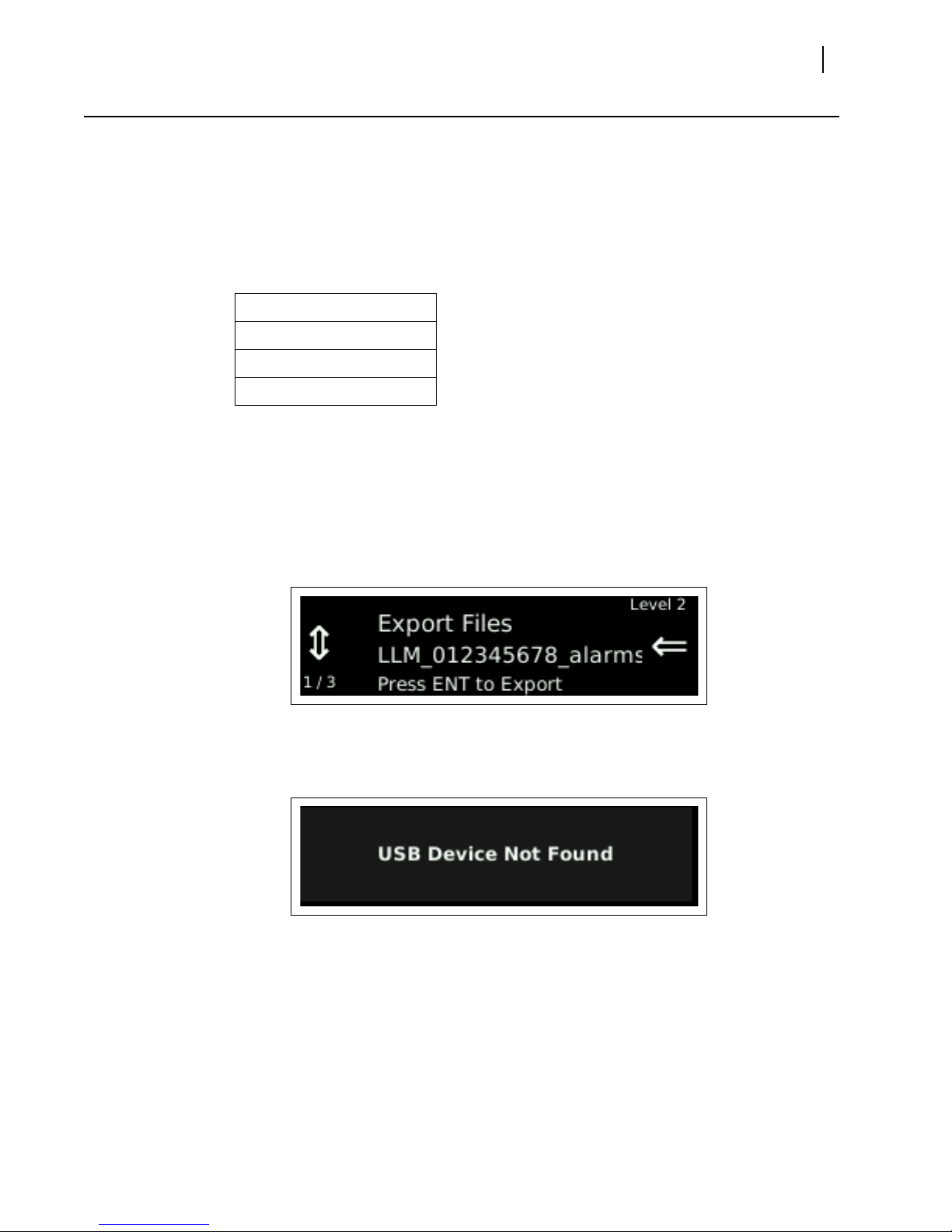
USB Utilities Menu Selections
Menu Selections
Table 4-10 USB Utilities Setup Menu
Selection Option
Export Files Flash
Update Feature
Upgrade
Menu Selection Descriptions
Export Files: This selection is used in coordination with a USB memory stick to export
logged data shown on the unit display. If the unit has the Dolby decode option, the
Model Number LLM-1770-D will be displayed.
a Plu
b Pr
g the USB device into the front of the unit.
ess the SETUP button to access the USB Utilities Export Files menu.
LLM-1770
Installation and Operation Manual
51
Figure 4-1 Export Files Menu
If a USB device is not connected
Not Found” for a period of three seconds.
Figure 4-2 Device Not Found Error Message
c Once the
d When
USB interface.
Flash Update: This selection is used in coordination with a USB memory stick to
update the unit.
a Download the latest firmware from the Harris Broadcast Customer Support websit e
(http://support.broadcast.harris.com/)
b Loa
c Plu
file has been selected, press the ENT button to begin the export.
the export is complete, the user can open the exported data on a PC via the
d the firmware on a USB memory stick.
g the USB device into the front of the unit.
to the system, the display will indicate “USB Device

Chapter 4
52
Setup Menu Functions
d Press the SETUP button to access the USB Utilities Flash Update menu.
Figure 4-3 Flash Update Menu Selection
If a USB device is not connected
to the system, the display will indicate “USB Device
Not Found” for a period of three seconds.
Figure 4-4 Device Not Found Error Message
e Navigate to
the LLM-1770_rXXXX.flu FLU file loaded on the USB stick using the Up
and Down navigation buttons.
Figure 4-5 Flash Update LLM-1770 FLU File Selection
f Once the
g When the
After the update has completed, a flash update log f
file has been selected, press the ENT button to begin the update.
update is complete, the unit will automatically power off or restart.
ile can be retrieved through
the web interface.
h V
erify that the firmware revision level r etr ieved from the About menu matches the
downloaded firmware revision.
Feature Upgrade: This selection is used in coordination with a USB memory stick
containing the feature file for the device to update the unit.
Before installing the LLM-1770 feature upgrade, verify that instrument’s firmware has been
updated to the most recent release.
a Press the SETUP button to access the setup menus.
b Obta
c Re
trieve the latest the firmware release from the Harris Broadcast Customer
Support website
tp://support.broadcast.harris.com/).
(ht
d Compar
If a firmware update is available, follow the instructions listed under Flash
from USB.
in the LLM-1770 firmware version from the About menu.
e the firmware versions.

LLM-1770
Installation and Operation Manual
If a later version of firmware is not available, follow the instructions listed
under
Installing the SDI Option
Flash from USB
e Download the latest firmware from the Harris Broadcast Customer Support websit e
(http://support.broadcast.harris.com/) and load it on a USB memory device.
f Plug the USB device into the front of the unit.
Press the SETUP button and access the USB Utilities Flash Update menu.
If a USB device is not connected to the system, the display will indicate “USB Device
Not Found” for a period of three seconds.
g Navigate to the LLM-1770_rXXXX.flu FLU file loaded on the USB stick using the up
and down buttons.
h Once the file has been selected, press the ENT button to begin the update.
i When the update is complete, the unit will automatically power off or restart.
After the update has completed, a flash update log file can be retrieved through
the web interface.
j Verify that the firmware revision retrieved from the About menu matches the
downloaded firmware revision.
53
About Menu
Installing the SDI Option
a Remove the USB memory stick from the LLM-1770 upgrade kit and plug it into the
USB slot located on the front of the unit.
b Press the SETUP button and access the USB Utilities Feature Upgrade menu.
c Navigate to the xxxxxxxxx.tvu (xxxxxxxxx is the 9-digit serial number of the unit to
be upgraded) file loaded on the USB stick using the up, down, and ENT butt ons on
the
LLM-1770 front panel.
d Press the ENT button to start the Feature Upgrade.
A message indicating the upgrade status will be displayed.
e Once the update is complete, the LLM-1770 will automatically power off.
f Press the power button and wait for the unit to power-up.
g Verify that the SDI option now appears in the About menu.
h Attach the supplied serial number to the LLM-1770.
This selection allows the display of the About screen (see Figure 4-6).
Menu Selections
Table 4-11 About Menu
Selection Option
Model Number
Serial Number
Options

Chapter 4
54
Setup Menu Functions
Table 4-11 Ab
out Menu (Continued)
Selection Option
Front Panel Rev.
Firmware Rev.
FPGA Rev.
DLB001 CPLD Rev.
Dolby Cat552
PLT001 CPLD Rev.
CPLD Rev.
PCB Rev.
Qt Rev.
File System Rev.
OS Rev.
Boot Rev.
MAC Address
IP Address
Menu Selection Descriptions
The About screen contains information specific to the LLM-1770, such as model, serial
number, options, revision levels, IP address, and MAC address.
Figure 4-6 About Display Screen
To enter the About Menu selection display
1 Pr
ess Setup, and then press the Up or Down navigation button until About is displayed.
2 Pr
ess ENT.
Figure 4-7 Setup About Display
To navigate the About menu selection information
Press the Up or
Down navigation button.

To exit the About display screen
Press the Setup or the Exit navigation button.
LLM-1770
Installation and Operation Manual
55

Chapter 4
56
Setup Menu Functions

5
57
Alarm Descriptions
The LLM-1770 alarms monitor audio signals, loudness, time code errors, and GPI errors.
Limits are selected in the Setup menu by cho
buttons.
Alarm Setup Menus
The Alarm Setup menu items, along with their corresponding Table and Description page
locations are listed in Table 5-1. An asterisk (*) is shown next to the default menu
selections.
Table 5-1 Alarms Setup
Selection Page
Meter based alarm setup Page 58
Loudness alarm setup Page 59
Dolby alarms setup Page 60
Time code alarm setup Page 60
GPI alarm setup Page 61
See page 35 for information on how to navigate through the Setup menus.
osing a value using the Up/Down navigation
Menu

Chapter 5
58
Alarm Descriptions
Meter Based Alarms Setup Menu
Menu Selections
Default values for meter-based alarms are mode dependent (i.e., ATSC A/85, EBU R 128,
ARIB TR-B32, or custom). Parameters are retained separately for each mode.
Table 5-2 Meter Based Alarms Setup Menu
Selection Selection Option Selection Option
Peak Audio
Loss of Sound
Digital Clip
Digital Mute
Enable Meter 1 •• 8
Level -30 to 0 dBFS
(The default selection
pends on the Loudness
de
Mode selection)
Duration 0 seconds to 60 seconds (2
econds*)
s
Enable Meter 1 •• 8
Level -60* to 0 dBFS
Duration 0 seconds to 60 seconds (2
s
econds*)
Enable Meter 1 •• 8
Sensitivity 1 to 100 CES (50 CES*)
Duration 0 seconds to 60 seconds (2
s
econds*)
Enable Meter 1 •• 8
Sensitivity 1 to 100 CES (50 CES*)
Duration 0 seconds to 60 seconds (2
s
econds*)
Menu Selection Descriptions
Peak Audio: The Peak Audio alarm occurs when the peak audio level exceeds the
adjustable limit for a period in excess of the duration setting. The level limit can be set
from -30 dBFS to 0 dBFS, in 1 dB increments. The peak audio duration can be set from
0 to 60 seconds.
Loss of Sound: The Loss of Sound alarm occurs when the peak amplitude falls below
an adjustable limit for a period in excess of the duration setting. The audio range is -60
dBFS to 0 dBFS, in 1 dB increments. The Loss of Sound duration can be set fr om 0 to 60
seconds.
Digital Clip: The Clip alarm occurs when the audio is at a maximum level for a period
in excess of the duration setting. For the LLM-1770, the accuracy of the audio clip
alarm is 0.
Digital Mute: The Mute alarm occurs when the audio sample is “0” for a period in
excess of the duration settings.
1 dB.

Loudness Alarm Setup Menu
Menu Selections
Table 5-3 Loudness Alarms Setup Menu
Selection Option Selection Option Selection Option
LLM-1770
Installation and Operation Manual
59
High Level Above
Low Level Below
Menu Selection Descriptions
High Level Above: The High Level Above target alarm occurs when the integrated
loudness level is higher than the target value plus the range above the d esire d loudness
level for a period in excess of the duration setting.
Low Level Below: The Low Level Below target alarm occurs when the integrated
loudness level is lower than target value plus the range below the desired loudness level
for a period in excess of the duration setting.
Enable
Level 0 to 10 LU
(The default selection
pends on the Loudness
de
Mode selection; see Note
below)
Duration 0 to 60 seconds (2
econds*)
s
Enable
Level 0 to 10 LU
(The default selection
pends on the Loudness
de
Mode selection; see Note
below)
Duration 0 to 60 seconds (2
econds*)
s
These values are mode-dependent (A TSC A/85, EBU R 128, ARIB TR-B 32, or Custom). When
you are in a specific mode you can only adjust the parameters associated with that
particular mode. When you change a loudness mode’s parameter, the High Level Above and
the Low Level Below target alarm parameters change also.

Chapter 5
60
Alarm Descriptions
Dolby Alarms Setup Menu
Menu Selections
Table 5-4 Dolby Alarms Setup Menu
Selection Option Selection Option Selection Option
Loss of VANC data
Dialnorm
Menu Selection Descriptions
Loss of V ANC data: The Loss of VANC data alarm occurs when Dolby E VANC ancillary
data packets are not present. Dolby E VANC packets are identified by DID: 0x45 and
SDID: 0x01 - 0x09. This alarm is enabled by SDID value.
Dialnorm: The Dialnorm alarm occurs when the Dolby E VANC metadata dialnorm
value for the enabled program falls outside selected minimum and maximum values for
the duration. If the Dialnorm Source in the Dolby Setup menu is set to VANC, the
dialnorm value from the Dolby D Essential payload is the specific dialnorm value used
for this alarm. If the Dialnorm Source is set to Dolby Decoder, the dialnorm value is
extracted from the metadata in the audio stream specified by the Input selection in the
Dolby Setup menu.This alarm is enabled by program.
SDID 1 •• SDID 9
Duration 0 to 60 seconds (2
seconds*)
Program 1 •• Program 8
Maximum -1* to -31
Minimum -1 to -31*
Duration 0 to 60 seconds (2
s
econds*)
Time Code Alarms Setup Menu
Menu Selections
Table 5-5 Time Code Alarms Setup Menu
Selection Option Selection Option Selection Option
LTC Loss of Time Code
Enable
Duration 0 to 600 seconds (240
seconds*)

Menu Selection Descriptions
LTC Loss of Time Code: The Loss of Time Code alarm indicates a loss of the LTC input
signal for a period in excess of the duration setting.
GPI Alarms Setup Menu
Menu Selections
Table 5-6 GPI Alarms Setup Menu
Selection Option Selection Option
GPI 1 Alarm Enable*
GPI 2 Alarm Enable*
Disable
LLM-1770
Installation and Operation Manual
61
GPI 3 Alarm Enable*
GPI 4 Alarm Enable*
Menu Selection Descriptions
The input GPIs have selectable functions to allow external control of the unit or to cause an
user alarm. The user alarm will be reported in the alarm log file and also registered on the
alarm status display.
Disable
Disable
Disable

Chapter 5
62
Alarm Descriptions

External Control
6
Microsoft® Internet Explorer ver sion 6 or later is the recommended browser.
Browser Interface
The website for each unit is accessed by pointing the web browser at the LLM-1770 IP
address. Before the default web screen appears, a user ID and password must be entered.
63
User ID: admin
Password: Harris
The user ID admin is the default user ID and Harris is the default password. These are set at
the factory but can be changed by the user via the Accounts web page. Keep in mind,
though that once the user ID and password have been changed, the only way to reset the
unit to the default user ID and its default password is to send the unit back to the factory
for repairs.
Once the user ID and password have been entere d, the web page appears, showing a list of
captures that have been stored in the LLM-1770’s internal memory. Use the web page to
the files or save them to disk. A sample web page is shown in Figure 6-1.
view
Figure 6-1 Sample Web Remote Display

64
Chapter 6
External Control
Across the top of the display is a series of buttons that allow access to the various external
control functions available to a user.
The Captures, Accounts, RCU, and Log Out control buttons are displayed across the top
of each external control functional display. The user can click on one of these buttons to
access the appropriate display.
The Captures button accesses the Index of Captures web remote display. See page 65
for an explanation of this display.
The Accounts button accesses the user account management display. See page 66 for
an explanation of this display.
The RCU button accesses the web-based control panel display. See page 64 for an
explanation of this display.
The About button accesses information specific to the LLM-1770, such as model, serial
number, options, revision levels, IP address, and MAC address. It also allow s a user to
download current LLM-1770 firmware and/or unlock LLM-1770 options. See page 53
an explanation of this display.
for
The Log Out button allows a user to exit the external control function.
Accessing the Web-Based Control Panel
Access the web browser as described on page 63. When the remote display
page opens, click the RCU button to access the web-based control panel.
Figure 6-2 Web-Based Control Panel
The LLM-1770 unit allows access to one controller at a time. If the unit receives a request
for another Web RCU session while previously established control session exists, the request
will be granted after the previously established session is terminated. A Web RCU session
that was terminated due to conflict with another control session can be re-established by
repeating the logon procedure.
The web-based LLM-1770 control panel operates identically to a physical LLM-1770 control
nel. Refer to Chapter 3, Ope
pa
ration for more information about panel operation.

Accessing the Index of Captures
Click the CAPTURES button on the web-based control panel to access the
web page containing the device’
Figure 6-3 Index of Captures Display
Installation and Operation Manual
s collected data.
LLM-1770
65
To open a file capture
Click the file capture name, and then fo
llow the on-screen instructions.
The LLM-1770 has two types of capture files: data files and alarm files. The names of these
files are determined in the Setup menu and use the serial number of the unit or a custom
string and the date. For more information see Appendix B, Lo
g File Contents.
To display an updated list of captures
Click the Ref
resh button.
The Index of Captures window does not refresh automatically. If you store one or more
captured displays but do not see it on the Index of Captures, click Refresh to see the
updated index.
To save a file capture
Click the file capture name, and then fo
llow the on-screen instructions.
To delete a single file capture
Click the Delete ch
eck box to the right of the file ca pt ure name, and then click the Delete
Files button.
To delete a list of file captures
1 Click the Select/Clear All bu
The De
lete check box to the right of each file capture is automatically selected. (Click the
tton.
individual check mark to deselect files as desired.)
2 Click the Delete Fil
The file captures are removed from
es button.
the Index of Captures list.

Chapter 6
66
External Control
Managing User Accounts
The LLM-1770 allows user accounts to be added or edited at the User,
System, or Administrator levels. Both User and System level accounts are
allowed general control of the unit.
Only Accounts at the Administrato
Adding Accounts
To add a new user account
1 Click the Accounts bu
The Accounts Display page opens.
r level can manage accounts.
tton on the web-based control panel.
Figure 6-4 Accounts Display Page
2 In the A
A unique identifier for the new account in the User ID text box.
A password for the new account (confirm the password by entering it again in the
dd new account(s) box, enter the following information:
Confirm Password text box).
An access level of User, System, or Administrator fr om the Access Level dr op-down list
box.
3 Click Sav
e to accept the new account, or click Reset to clear the previously entered
information and start again.

Editing Accounts
To edit password and access level information
1 Click the Accounts button on the web-based con trol pane l.
The Accounts Display page opens.
2 In the Edit/Delete existing account(s) box, locate the unique identifier in the User ID text
box for the account to be edited.
3 Change one or more of the following fields as appropriate:
Change a password for the existing account by entering a new password in the New
Password text box.
Confirm the password by entering it again in the Confirm Password text box.
Change the user access level by making a different selection at the Access Level
drop-down list box.
4 Click Save to accept the account changes, or click Reset to restore the original information
and start again.
Deleting Accounts
LLM-1770
Installation and Operation Manual
67
To delete a user account
1 Click the Accounts button on the web-based con trol pane l.
The Accounts Display page opens.
2 In the Edit/Delete existing account(s) box, locate the unique identifier in the User ID text
box for the account to be deleted.
3 Click the Delete check box to the right of the account to be deleted.
4 Click Save.
The account is deleted.

Chapter 6
68
External Control
Accessing the About Page
The About screen contains information specific to the LLM-1770, such as model, serial
number, options, revision levels, IP address, and MAC address.
The About display page opens.
Click the About button on the web-based contr ol panel t o access th e web
page containing the device’s data.
Figure 6-5 About Display Page
To update the LLM-1770 firmware
1 Download the latest firmware from the Harris Broadcast Customer Support website
(http://support.broadcast.harris.com/)
2 Navigate to
3 Once the
4 When the
the download location of the LLM-1770_rXXXX.flu FLU file.
file has been selected, click the Update button to begin the update.
update is complete, the unit will automatically power off or restart.
After the update has completed, a flash update log f
interface.
5 V
erify that the firmware r evision level retrieved from the About menu matches the
downloaded firmware revision.
ile can be retrieved through the web

LLM-1770
Installation and Operation Manual
To unlock the SDI option
1 Enter the 9-digit serial number of the unit to be upgraded in the Enter Upgrade Key field in
the Unlock Options box.
2 Press the Upgrade button to start the feature upgrade.
A message on the Unit display indicates the upgrade status.
3 Once the update is complete, the LLM will automatically pow er off.
4 Press the power button and wait for the unit to power-up.
5 Verify that the SDI option now appears in the About menu.
6 Attach the supplied serial number to the Unit.
69

70
Chapter 6
External Control

7
71
Troubleshooting
CAUTION: These instructions are for use by qualified personnel only. T o reduce the
risk of electric shock, do not perform this installation or any servicing unless you
are qualified to do so. Refer all servicing to qualified service personnel.
When power is applied to the unit, the display shows the startup screen for about 45
seconds.
Initial Checks
Restarting
1 Push and
2 Pr
If the LLM-1770 is not functioning properly, first verify the following:
The LLM-1770 is connected to a power source (11-17 VDC).
All cables are correctly connected (see Connecting the LLM-1770 on page 16).
Initial difficulties with operation or display can be due to improper setup. Review the Setup
s (see Setup Menu Functions
menu
have been made for the signal requirements.
If a problem persists after the cables are correctly connected and the unit is set up, restart
the unit by doing the following:
hold the SETUP and CLR buttons for a minimum of five seconds until the SYSTEM
RESET message appears on the display .
ess and hold the ENT button to reset the unit’s configuration. All front panel and Setup
menu selections will be reset to the factory default settings.
on page 35) to ensure that the proper adjustments

Chapter 7
72
Troubleshooting
Problems, Causes, and Solutions
Table 7-1 LLM-1770: Problems, Causes, and Solutions
Problem/Symptom Solution or Explanation
The Loudness displays are not changing or
stuck at -70.0 LKFS.
are
Only one value is being shown on the
lo
udness display.
There is no sound on the headphone
tput.
ou
The thumbnail does not display colors
orrectly.
c
There are no communications on the
hernet port
Et
If the problem still exists afte
Support
on page 12 for further instructions.
r troubleshooting the LLM-1770, see LLM-1770 Service and
Verify that the audio meters are mapped to
the correct inputs.
Verify that the loudness mapping is
correctly configured.
Verify that the unit is in
the RUN state.
Loudness displays are configurable via the
Setup menus. Adjustments can be made
based upon user preferences.
Adjust the headphone volume or select the
proper channel to be monitored through
the Headphone Setup menu selections.
The thumbnail is a basic representation of
the decoded SDI picture. The OLED does
not have enough color depth to correctly
display the picture.
Verify the network settings through the
Setup menu.

8
73
Specifications
Specifications are subject to change without notice.
Inputs
Table 8-1 3 Gb/s-SDI Input Specifications
Item Specification
Input type 1 active looping input
Input connector type BNC fe ma le
Input impedance 75 no
Signal source amplitude 800 mV nominal
Signal source DC offset ± 0.5 V
Input return loss -10
Cable EQ 80 M Belden 16
Table 8-2 HD-SDI Input Specifications
Item Specification
Input type 1 active looping input
Input connector type BNC fe ma le
Input impedance 75 no
Signal source amplitude 800 mV nominal
Signal source DC offset ± 0.5 V
minal
dB, 1.485 GHz - 2.97 GHz
minal
94A
Input return loss -15
Cable EQ 100
Table 8-3 SD-SDI Input Specifications
Item Specification
Input type 1 active looping input
Input connector type BNC fe ma le
Input impedance 75 no
dB 5 MHz-1.485 GHz
M Belden 8281
minal

74
Chapter 8
Specifications
Table 8-3 SD-SDI I
nput Specifications (Continued)
Item Specification
Signal source amplitude 800 mV nominal
Signal source DC offset ± 0.5 V
Input return loss Cable EQ 300
Table 8-4 Digital Audio
Input Specifications
25 dB 5 MHz-270 MHz
M Belden 8281
Item Specification
Audio formats AES/EBU, embedded audio
AES input connector type 4 BNC female
AES input impedance 75 no
AES input return loss 25
minal
dB, 0.1MHz to 6MHz (Unbalanced)
AES input level 0.2 to 2.0 V
AES input sample rate
Audio inputs are sample rate converted
to 48 kHz.
32 kHz
44.1 kHz
48 kHz
88.2 kHz
96 kHz
Outputs
Meter accuracy over freque
ncy ±0.1 dB from 20 Hz to 19 kHz with 0 to -40
dBFS sine wave input, except for within 7
Hz of some submultiples of the 240 kHz
oversampling frequency
Meter bars on display subject to display
lution
reso
Table 8-5 3 Gb/s-SDI, HD-SDI, SD-SDI, Output Specifications
Item Specification
Output connector type 1 BNC female
Output impedance 75
Output return loss -15
dB,5 MHz to 1.485 GHz
-10
dB, 1.485 GHz to 3 GHz
Output signal level 800 mV ±10%
Output DC offset 0.0 V ± 0.5 V

LLM-1770
Installation and Operatoin Manual
75
OLED Display
Table 8-5 3 Gb/s-S
Item Specification
Output rise and fall time
270 MHz
1.484 GHz
2.97 GHz
Table 8-6 Display Specifications
Item Specification
General 256×64 OLED display for device
DI, HD-SDI, SD-SDI, Output Specifications (Continued)
Between 400 to 700 ps (20 to 80%
amplitude)
500 ps
< 270 ps (20 to 80% amplitude), not
iffering by more than 100 ps
d
< 135 ps (20 to 80% amplitude), not
dif
fering by more than 50 ps
nfiguration and obtaining loudness
co
determinations
, not differing by more than
Communication Interfaces
Table 8-7 Communication Interfaces
Item Specification
Ethernet 1 Ethernet port RJ-45 10/100 Base-T
USB 1 USB 2.0 host port
LTC/GPIO 1 LTC/GPIO connector 15 female pin D-sub
Ethernet
Table 8-8 Ethernet Specifications
Item Specification
Standard 10/100 Base-T conforms to IEEE802.3
Connector RJ-45
Performance metric Transfer a downloaded file to a PC in 30
connector
s
econds, dedicated LAN

Chapter 8
76
Specifications
Power Requirements
Table 8-9 Power Requirements
Item Specification
Power connector 15 VDC nominal
Power consumption 10 W nominal
Over-voltage protection +50 VDC nominal
Non-resetting fuse 2A, 72 VDC
11 VDC minimum, 18 VDC maximum
Mechanical
Environmental
Table 8-10 Mechanical Specifications
Item Specification
Height 1.75 in. (4.45 cm)
Width 8.5 in. (21.59 cm)
Depth 6.60 in. (16.76 cm)
Weight 1.716 lb (0.77 kg)
Table 8-11 Environmental Specifications
Item Specification
Operating temperature 32° to °122°F (0° to +50°C)
Storage temperature -22° to +149°F (-30° to +65°C)
Humidity (non condensing)
Altitude Operating: 6562 ft (2000 m)
Operating: 20% to 80%
Non-operating: 5% to 90%
Transportation 24.00 in. (60.96 cm) i mpact drop survivable
Pollution degree Pollution degree 2
in
original factory packaging

Standard and Optional Accessories
Table 8-12 Standard Accessories
Item Specification
Standard accessories
Table 8-13 Optional Accessories
Item Specification
LLM-1770
Installation and Operatoin Manual
LLM-1770 Installation and Operation
Manual on CD
Breakout connector for LTC/GPI
One power cord
One power supply assembly
77
TVM-WRTY-3YR Full extended warranty plan:
Adds three
years to the standard two-year warranty
LLM-OPT-SDI Software keyable upgrade to activate
HD-
SDI and/or 3 Gb/s input
LLM-OPT-SDI-F Field-upgradable software keyable upgrade
to activate
HD-SDI and/or 3 Gb/s input
BLK-5 Blank panel for DRT-4A
DRT-4A Double rack mount case
PTC-4 Portable case with tilt stand

78
Chapter 8
Specifications

Pinouts
A
LTC/GPI D-Sub Connector
79
Figure A-1 LTC/GPI 15-Pin, Female, D-Sub Connector
Table A-1 Pin
Pinout Signal Pinout Signal
1 ERROR SUM 9 LTC GND
2 GPI IN 1 10 LTC+
3 GPI IN 2 11 LTC4 GPI IN 3 12 N/C
5 GPI IN 4 13 GND
6 ERROR SUM RETURN 14 N/C
7 GND 15 GND
8 GND
outs for LTC/GPI Connector

Appendix A
80
Pinouts
Ethernet RJ45 Connector
Figure A-2 Ethernet RJ45 Connector
Table A-2 Et
Pinout Signal Pinout Signal
1 TX+ 5 N.C.
2 TX- 6 RX3 RX+ 7 N.C.
4 N.C. 8 N.C.
Power Connector
hernet RJ45 Connector Pinouts
Figure A-3 Power Connector
Table A-3 Power Connector P
Pinout Signal Pinout Signal
1 GND 3 N.C.
2 N.C. 4 Power
inouts

B
Log File Contents
The LLM-1770 has three types of capture files: data, and alarms, and summary files.
A data file represents an entir e day’s worth of raw loudness values. Entries are recorded
at a 100 ms rate for both program 1 and program 2.
An alarm file represents an entire day’s worth of alarm events. Alarm events are written
to the log as they occur. Menu options control how the box operates if the number of
alarms exceeds the storage capabilities of the device.
A summary file represents a snapshot event of loudness measurements and settings.
You can manually trigger an event by pressing the CLR button. An event is
automatically triggered 24 hours after the last clear event.
A new log file is created when the system
time rolls over to the next day.
81
Naming Conventions
LLM_<field string>_<type>_<date>_.csv where:
<field string> is either the serial number of the unit or a 9 char custom string
<type> is either “alarms”, “data”, or “summary”
<date> is the date that the file was cr
The names of these files are determined in the Setup menu and use the serial number of the
unit or a custom string and the date.
eated in the format of “YYYY-MM-DD”

Appendix B
82
Log File Contents
File Type Contents and Samples
Data File Contents
Table B-1 Data File Contents
Column Header Description
File Sequence Number An incremental number u
Time Stamp Associated system time
Time Code Associated time code that the sample was
Program 1 Raw Data Raw program 1 data for the current sample
Program 2 Raw Data Raw program 2 data for the current sample
Sample Data File
Table B-2 Sample Data File
File
quence
Se
Number
5424 13:43:02.4 00:00:00:00 -28.6 -20
5425 13:43:02.5 00:00:00:00 -25.1 -20
5426 13:43:02.6 00:00:00:00 -23.8 -20
order that the samples were collected
taken
tak
period in
period in
Time Stamp Time Code
en
LKFS
LKFS
Program 1
Raw Data
sed to identify the
that the sample was
Program 2
Raw Data
5427 13:43:02.7 00:00:00:00 -24 -20
5428 13:43:02.8 00:00:00:00 -24.4 -20
5429 13:43:02.9 00:00:00:00 -24.3 -20
5430 13:43:03.0 00:00:00:00 -24.4 -20
5431 13:43:03.1 00:00:00:00 -25.9 -20
5432 13:43:03.2 00:00:00:00 -24.9 -20
5433 13:43:03.3 00:00:00:00 -26.2 -20
5434 13:43:03.4 00:00:00:00 -31.4 -20
5435 13:43:03.5 00:00:00:00 -23.9 -20
Format Time Stamp column as custom hh:mm:ss.0 for time stamp to display correctly.

Alarm File Contents
Table B-3 Alarm File Contents
Column Header Description
Alarm Name The name of the alarm
Start Time Associated system time that the alarm was
Start Time Code Associated time code that the alarm was
tr
iggered
tr
iggered
LLM-1770
Installation and Operation Manual
83
Duration The total duration that the ala
Peak Value Reported Peak Value (RPV) If available, this
Event Either T
Sample Alarm File
Table B-4 Sample Alarm File
Alarm Name
LTC Loss of Time Code 13:46:06 0:0:0:0 --:--:-- NO RPV Triggered
Start
me
Ti
The duration is filled in after the
alarm clears.
will represent the peak value that caused
the alarm to trigger
If no RPV value is associated with the alarm,
NO RPV is indicated
riggered or Cleared:
Triggered indicates the leading edge of
the alarm.
Cleared indicates the trailing edge of the
alarm.
Start
Time
Code
Duration
Peak
Value
rm occurred
Event
LTC Loss of Time Code 13:46:06 0:0:0:0 0:00:14 NO RPV Cleared
Peak Audio Ch 1 13:47:08 0:0:0:0 --:--:-- -13 dBFS Triggered
Peak Audio Ch 2 13:47:08 0:0:0:0 --:--:-- -13 dBFS Triggered
Peak Audio Ch 2 13:47:08 0:0:0:0 0:00:12 -13 dBFS Cleared
Peak Audio Ch 2 13:47:20 0:0:0:0 --:--:-- -28 dBFS Triggered
Peak Audio Ch 1 13:47:08 0:0:0:0 0:00:14 -13 dBFS Cleared

Appendix B
84
Log File Contents
Summary File Contents
Table B-5 Summary File Contents
Column Header Description
Start Date Associated system date whe
Start Time Associated system time whe
End Date Associated system date whe
End Time Associated system time whe
Start Time Code Associated time code value
n this measurement began
n this measurement began
n this measurement ended
n this measurement ended
when this measurement
began
End Time Code Associated time code value
when this measurement
ended
Mode The current loudness mode of the device
Prg 1 Loudness Value The measured program loudness val
ue over the indicated
time
Max Loudness 1 Value The maximum integrated lo
udness detected
Loudness Range 1 Value The calculated loudness range
Loudness 1 Mapping The input source to loudness channel mapping associated
wit
h the indicated program
Prg 2 Loudness Value The measured program loudness val
ue over the indicated
time
Max Loudness 2 Value The maximum integrated lo
udness detected
Loudness Range 2 Value The calculated loudness range
Loudness 2 Mapping The input source to loudness channel mapping associated
wit
h the indicated program
Dialnorm Value The extracted VANC Dialnorm value
Prg Loudness Relative Gating *
Prg Loudness Gating
*
Threshold
Loudness Integration Time *
Loudness Range Relative
*
Gating
Loudness Range Gating
*
Threshold
Target Loudness *
Absolute Gating *
Dialnorm SDID *
Dialnorm Program *
*The associated parameter values as entered through the menu systems.

C
85
Glossary
601. An international standard (ITU-R BT.601) for component digital television. It defines
the sampling systems, matrix values, and filter characteristics for digital television.
8 VSB. Vestigial sideband modulation with 8 discrete amplitude levels.
16 VSB. Vestigial sideband modulation with 16 discrete amplitude levels.
Advanced Television Systems Committee (ATSC). The parent organization that
developed, tested and described the form and function of the US digital television formats.
AES/EBU. A digital audio standard established jointly by the Audio Engineering Society
(AES) and the European Broadcasting Union (EBU).
Anchor Element. The perceptual loudness reference point or element around which other
elements are balanced in producing the final mix of the content, or that a reasonable viewer
would focus on when setting the volume control.
Artifacts. Unwanted visible effects in the picture created by disturbances in the
transmission or image processing, such as edge crawl or “hanging dots” in analog pictures,
or “pixilation” in digital pictures.
Aspect Ratio. The ratio of horizontal to vertical dimensions. A square has an aspect of 1:1
since the horizontal and vertical measurements are always equal. Current television screen
aspect ratios are 4:3 and 16:9.
Asynchronous Serial Interface (ASI). A transmission method adopted by the DVB, and
called DVB-ASI. The transmission method allows for the transport of varying data payloads
in a constant data stream. The DVB-ASI transport stream rate is 270 Mb/s.
Audio Breakaway. Routing vide o and accompanying audio in separate signal paths.
Audio-Follow. Routing video and accompanying audio together in the same signal path.
Auto Trans. Automatic transition; the execution of a single wipe or fade from current
picture to another picture by way of an automatic device.
Bandwidth. The range of frequencies used to transmit information such as picture and
sound.
Baseband Video. An unmodulated video signal.
Black. Also color black, blackburst. A composite color video signal that has the composit e
sync, reference burst, and a black video signal.

86
Appendix C
Glossary
Blanking Processor. A circuit which removes sync, burst and blanking from the program
video and then replaces it with sync, burst and blanking from the reference input. The
process ensures constant sync and burst levels on program video.
Border. An electronically-generated picture member which is used in wipes to separate the
two video sources used in the wipe. It is of even thickness and has color produced by the
matte generator.
Broadcast Legal. Encoding video signal parameters to conform to prescribed limits for
broadcast. Encoding rules vary by NTSC, PAL, country and broadcast facility.
BTSC. Broadcast Television Standards Committee. A US standard for stereo audio encoding
in NTSC broadcast television.
CAV. Component Analog Video
CDP. Caption Distribution Packet
CES. Consecutive Errored Samples
Composite Video. A single video signal that includes all color video and timing
information. A composite signal includes luminance, chrominance, blanking pulses, sync
pulses and color burst information.
Chrominance. The color portion of a video signal that represents the saturation and hue.
Black, gray and white have no chrominance; color sign als have both chrominance and
luminance.
CH. Chroma
Chrominance/Luminance Delay. A measurement that indicates the amount to which
chrominance and luminance are aligned with respect to each other. A low C/L delay figure
can minimize the effects of ghosts or color offset on the received picture.
C/L Delay. Chrominance/Luminance Delay
Clipping. The electronic process of shearing off the peaks of either the white or black
excursions of a video signal for limiting purposes. Clipping is often performed prior to
modulation to limit the signal.
CMRR. Common Mode Rejection Ratio
Color Burst. The portion of a color video signal which co nt ains a shor t s ample of t he color
subcarrier. It is used as a color synchronization signal to establish a reference for the color
information following it and is used by a color monitor to decode the color portion of a
video signal. The color burst acts as both amplitude and phase reference for color hue and
intensity. The color oscillator of a color television receiver is phase locked to the color burst.
Composite Sync. A signal consisting of horizontal sync pulses, vertical sync pulses and
equalizing pulses only.
CRC. Cyclical Redundancy Check
Crosspoint. An electronic switch, us ually controlled by a button on the panel. Contr ol logic
will allow for only one crosspoint, for each bus, to be switched “ON” on at a time.

LLM-1770
Installation and Operation Manual
D/A. Conversion of digital to analog signals.
DA. Distribution Amplifier
dBTP. Decibels relative to nominal 100%, true-peak
Data Element. An item of data as represented before encoding and after decoding.
Decoded Stream. The decoded reconstruction of a compressed bit stream.
Decibel (dB). A logarithmic measure of the ratio between two powers, voltages, currents,
sound intensities, etc. Signal-to-noise ratios are expressed in decibels.
Default. A factory preset value or condition.
Demodulator. A receiver, such as for television broadcast, cable, and closed circuit
applications. A TV demodulator receives and processes off-air or cable RF signals and
provides baseband video and audio outputs.
DHCP. Dynamic Host Configuration Protocol.
87
Dialnorm. An AC-3 metadata parameter, numerically equal to the absolute value of the
Dialog Level, carried in the AC-3 bit stream.
Dialog Level. The loudness, in LKFS units, of the Anchor Element.
Differential Gain. A measurement that specifies how much the chrominance gain is
affected by the luminance level. Expressed as a percentage showing the largest amplitude
change between any two levels, it indicates how much color saturation variance occurs
when the luminance level changes.
Differential Phase. A peak-to-peak measurement that specifies the extent to which the
chrominance phase is affected by the luminance level. Expressed in degrees of subcarrier
phase, it indicates how much hue shift occurs with luminance level changes.
Digital Video Broadcasting (DVB). A specific project office of the European Broadcast
Union. This group has produced a set of digital broadcasting standards.
DSK. Down Stream Key, a keyer which is electronically located after (or down stream from)
all other functions of a switcher. The key resulting will appear to be on top of all other
pictures from the switcher.
Duration. Duration is used to determine how long an error must persist before it is
reported. Setting the duration to 0 causes an error to be displayed as soon as the CES value
is met.
DVITC, D-VITC. Digital Vertical Interval Time Code. Timecode information stored on
specific lines in the vertical blanking interval of a television signal.
EAV. End of Active Video in component digital systems.
EBU. European Broadcasting Union
Editor. A device or system which controls video tape recorders, video switchers, and other
related devices in order to electronically splice segments of recorded video into a finished
production.

88
Appendix C
Glossary
EDH. Error Detection and Handling. A recommended practice defined in SMPTE RP 165. A
system to generate and then detect video data errors in serial digital video systems.
Effects Keyer. A keyer which is electronically located in the mix/wipe generator portion of
a switcher. The resulting key would appear under the down stream key.
EIA Rack Space or Unit. A specific size as designated by the Electronics Industry
Association. The rack unit is 19 inches wide, and is 1.75 inches tall. A device which requires
3 EIA rack units is 19 inches wide and 5.25 inches (3x1.75 = 5.25) tall.
Elementary Stream (ES). A generic term for o ne of the coded video, audio or other
variable length bit streams which are packetized to form MPEG-2 transport streams.
Consists of compressed data from a single source (audio, video, data, etc.). One elementary
stream is carried in a sequence of PES packets with one and only one stream ID.
Embedded Audio. Digital audio information multiplexed onto a serial digital data stream.
Up to sixteen channels can be multiplexed on a single stream of 601 video, minimizing
cabling and routing requirement.
ENG. Electronic News Gathering
Encoded Clip Softness. In the encoded legalization process, “softness,” as applied to
encoded clips, refers to the processing of the video at the point of the clip. The clips are
applied in YCbCr color space. The clip point is either an immediate limit (no softness) or will
have a range of values leading to the clip point, all reduced to smooth the clip point to a
less immediate limit (softness).
Encoded Legalization. Limiting of the luminance and color difference signals such that,
once encoded into a composite video signal, the resultant encoded video does not violate
the maximum or minimum signal levels as defined by the specific encoding rules. NTSC and
PAL video plus various users of these types of video have many varied rules for maximum
and minimum encoding limits. Encoded legalization usually calculates first the encoded
luminance value and then the corresponding chroma value to make legalization
judgements.
Encoded Video. A combined single video signal that is constructed from either separate
GRB or luminance and two color difference video signals. NTSC, PAL, and SECAM are all
examples of encoded video.
Envelope Detection. An RF signal detection technique that does not respond to phase
variations in the carrier signal, enabling measurement of a transmitter’s incidental phase.
When used together with synchronous detection, envelope detection helps isolate either
video and/or RF as the causes of phase distortion.
External Key Input. This is an alternate source for key cut. This is usually a separate
external input to a switcher
Fade-thru-Black. A production technique which is a two step process. The first step will
fade the program video to black. The second step will fade from black to the video selected
on the preview bus. This is usually used in major scene transitions.
Fade-to-Black. A production technique which simply fades the program video to black and
program audio to silent. This is used to end programs and to escape from embarrassing
pictures or sounds.

LLM-1770
Installation and Operation Manual
Field. A picture or picture portion which is produced within one cycle of vertical
synchronization. In interlaced systems, a full picture or frame requires two consecutive
fields.
FM Trap. A circuit designed to minimize potential interference from strong FM signals in
receiving equipment, such as a TV demodulator. For example, an FM trap can attenuate
signals between 88-108 MHz to reduce interference on NTSC television channel 6.
Frame. A single full resolution picture as viewed in either a video or film system. In the case
of interlaced video, two consecutive fields provide all of the information of one frame. In
non-interlaced systems, one cycle of vertical synchronization produces a frame. A 60 Hz
interlaced system, produces 30 frames of video in one second. A 60 Hz progressive (or
non-interlaced) system, produces 60 frames of video in one second. Common frame rates
are 24 (film) 25, 29.97, 30, 50, 59.94 and 60.
Frame Synchronizer. An electronic device that synchronizes two or more video signals.
Using one input as a reference, it locks a second signal to the reference.
Frame Store. An electronic method of capturing and storing a single frame of video.
Gamma. This term applies to the linearity of the change from black to white. Gamma
controls adjust the gray or 50% point of the video either up or down, with the effect of
changing the gray level of the video.
89
Gamut. The whole or total of whatever is being addressed. In color space, gamut refers to
all colors which are included in a particularly defined color group, such as 601 gamut.
Genlock (Generator Lock). A method of synchronization involving the generation of a
video signal that is time and phase locked with another signal.
GPI. General Purpose Interface
Headend. In a cable TV system, the facilities where program sources (satellite, terrestrial,
VTR, local) are received and remodulated for distribution through a cable plant.
High Definition Television (HDTV). High definition television has a resolution of
approximately twice that of conventional television in both the horizontal (H) and vertical
(V) dimensions and a picture aspect ratio (H to V) of 16:9.
High Level. A range of allowed picture parameters defined by the MPEG-2 video coding
specification which corresponds to high definition television.
HRC. Harmonically-Related Carrier
Hue. Color tint
ICPM. Incidental Carrier Phase Modulation. A measurement of picture carrier phase
distortion (affected by the vid eo signal level) that occurs in the transmitter.
Installation Categories. Categories of measurements that occur on circuits attached or
not attached to a live electrical supply outlet. Installation Categories are as follows:
Category I is for measurements that occur on circuits not attached to a live electrical
supply outlet (115/230 VAC). The voltages come from secondary power sources. The
secondary power source includes circuits energized by low-voltage sources and
electronics such as batteries.

90
Appendix C
Glossary
Category II is for measurements that occur on circuits attached to a live electrical supply
outlet (115/230 VAC).
Category III is for measurements that occur on equipment permanently connected to
the building. The distribution level equipment are usually fixed installations and circuit
breakers.
Category IV is for measurements that occur at the main electrical power supply.
IP. Internet Protocol
IRC. Incrementally-Related Carrier
I.R.E. Refers to the Institute of Radio Engineers, and is used as a unit of measurement. In
NTSC television, 1 volt of signal equals 140 IRE units.
ISP. Internet Service Provider
Jitter. A deformation of a signal affected by poor synchronization.
Key. An effect in television where a selected portion of background video is removed and
replaced with another video.
Key Cut. In a key effect, this is the video which des ignates the portion of background video
which is removed.
Key Fill. In a key effect, this is the video which is used to r eplace the portion of background
video which was removed. This may be the same video as the Key Cut video.
Key Invert. In a key effect, this is an electronic action which reverses the polarity of the key
cut signal. It makes black appear as white, and white appear as black.
Key Mask. In a key effect, it uses a wipe pattern from the wi pe pattern generator to restrict
the key cut from removing video in a portion of the screen. This requires the use of the wipe
pattern generator and the Mask/Preset Size controls.
Key Source. Another term which is the same as key cut.
Legalization. The modification of serial digital video to conform to analog color space
rules, as required by users.
LCD. Liquid Crystal Display
LED. Light-Emitting Diode
LFE. Low Frequency Effects
Lissajous. A display of the amplitude and phase relationships between two input signals.
LKFS. Loudness, K weighted, relative to nominal full scale. The LKFS unit is equivalent to a
decibel in that an increase in the level of a signal by 1 dB will cause the loudness reading to
increase by 1LKFS. A unit of LKFS is equivalent to a decibel.
If a 0 dB full-scale 1 kHz sine wave is input applied to the left, centre, or right channel input,
the indicated loudness will equal -3.01 LKFS. The weighting coefficients are different for
each channel.
LS. Left Surround

LLM-1770
Installation and Operation Manual
LTC. Longitudinal Time Code, A SMPTE timecode standard usually recorded onto the linear
audio track of a VTR.
LU. Loudness Unit. The loudness unit is the scale unit of the loudness meter. The value of
the program in loudness units represents the loss or gain (dB) that is required to bring the
program to 0 LU, e.g. a program that reads -10 LU will require 10 dB of gain to bring that
program up to a reading of 0 LU. (From BS.1771)
LUFS. Loudness unit, referenced to Full Scale. (This is the EBU recommended unit;
equivalent to LKFS.)
Luminance. The degree of brightness (black and white portion of the video signal) at any
given point in the video image. A video si gnal is compris ed of lu minance, chrominance and
sync. If luminance is high, the picture is bright and if low the pict ure is dark. Changing the
chrominance does not affect the brightness of the picture.
Main Level. A range of allowed picture parameters defined by the MPEG-2 video coding
specification with maximum resolution equivalent to standard definition television.
Main Profile. A subset of the syntax of the MPEG-2 video coding specification that is
supported over a large range of applications. Applications include, MP@HL (Main profile at
high level) and MP@ML (Main profile at main level).
91
Mask/Preset Size. Uses the wipe pattern generator in the keyer portion of the effects
generator. This is used to adjust the size of a preset pattern or for adjusting the size of a
mask to block a portion of the key cut (source) from use in the keyer.
Matte Generator. An internal generator which can make any color, is used for border
color and may be used for key fill. It is identical to the Color Background Generator, but
simply used in other areas of the switcher.
Mbps. Megabits Per Second
mV. Millivolts
M/E. Mix/Effects System
MP@HL. Main profile at high level
MP@ML. Main profile at main level
MPEG. Refers to standards developed by the ISO/IEC JTC1/SC29 WG11, Moving Picture
Experts Group.
MPEG-2. Refers to ISO/IEC standards 13818-1 (Systems), 13818-2 (Video), 13818-3
(Audio), and 13818-4 (Compliance).
Multi-Level Effects. Applies to any effects generator which can do more than one effect
at a time. Typically, a multi level switcher can produce a Key and a Background transit ion in
the same effects generator at one time.
NTSC. National Television Systems Committee, the color television system used in the
United States, Canada, Mexico and Japan.
NVRAM. Nonvolatile RAM

92
Appendix C
Glossary
OLED. Organic light-emitting diode; a graphical color display for use as television screens,
computer displays, portable system screens, and in advertising and information board
applications
Packet Identifier (PID). A unique integer value used to associate elementary streams of a
program in a single or multi-program transp ort stream.
Packet. A packet consists of a header followed by a number of contiguous bytes from an
elementary data stream. It is a layer in the system coding syntax.
Packetized Elementary Stream (PES). The data structure used to carry elementary stream
data. The packets consist of a header followed by payload data, and a stream is a series of
packets which form an elementary stream and have a single stream identification.
PAL. Phase Alternation Line; the standard color television system in many European and
other countries.
Passive Looping. Video and audio signals routed through components, even if power is
removed. Signals are not amplified or processed, maintaining transparency.
Pedestal Level. An offset used in a video system to separate the active video from the
blanking level by maintaining the black level above the blanking level by a small amount.
Pixel. A Picture cell or Picture element representing one sample of picture in formation, such
as an individual sample of R, G, B, luminance or chrominance.
Pollution Degree. A measurement of the foreign materials such as conductive dust, gas,
and moisture between the internal areas of the product and the outside environment.
Pollution Degrees are 1,2 3, and 4.
Pollution Degree 1 describes conditions where no pollution occurs or only dry,
nonconductive pollution occurs. This is normal for equipment located in clean rooms.
The pollution classified under Pollution Degree 1 has no environmental influence.
Pollution Degree 2 describes conditions wher e dry, nonconductive pollution occurs. This
is normal in an office environment. Temporary conductivity caused by condensation
may occur when the unit is not in service.
Pollution Degree 3 describes conditions where conductive pollution occurs, or dry,
nonconductive pollution occurs due to condensation. Rooms that cannot maintain the
moisture or temperature f all into this category. The location can only protect from
outside weather conditions such as direct sunlight, rain, snow, and wind. Industrial
areas can fall under Pollution Degree 3.
Pollution Degree 4 describes pollution that generates persistent conductivity through
conductive dust, rain, or snow. Pollution Degree 4 is for outdoor locations.
Preset. Refers to establishing any condition prior to use on the Pr ogram output. This term is
used in reference to wipe patterns and is often interchanged with Preview.
Preview. The video output channel used to view the intended Program results prior to the
execution of the next transition.
PRO Audio. A transmitted audio channel for talent cueing via Interrupt Foldback (IFB) to
ENG vans and remote applications. Some demodulators support PRO audio monitoring.

LLM-1770
Installation and Operation Manual
Program. A transport stream combination of a video stream and one or more audio and
data streams associated with that video stream. In analog terms, “Program” refers to the
Base Band video and audio produced by the final output of a switch er.
Program Association Table (PAT). A list of all programs that are in the ATSC data stream.
Program Map Table (PMT). A listing of all elementary streams that comprise a complete
(television) program.
Program Clock Reference (PCR). This is a time reference signal that is placed in MPEG
streams for the purpose of time coordinating various data streams.
Program and System Information Protocol (PSIP). Information sent out as part of an
ATSC transport stream which lists all of the video, audio, data and program information
contained in the stream. This is the “TV guide” for a given stream.
Progressive Scanning. Also non-interlaced. A system of video scanning where lines of a
picture are transmitted consecutively, such as with VGA monitor displays.
Push-push Toggle Switch. An electro-mechanical device which, when pushed, alternates
the condition of the switch. Push once, it’s off, push again, it’s on.
93
Quadrature Output. An output in a television demodulator used for measuring Incidental
Carrier Phase Modulation (ICPM) in a transmitter.
QPSK. Quadrature Phase Shift Keying, typically used by satellite downlinks.
QAM. Quadrature Amplitude Modulation, the technique used by cable TV systems
(64-QAM and 256-QAM) to remodulate signals for distribution in a cable plant.
GRB Legalization. Limiting of luminance and color differ ence video signals such that, once
transcoded into GRB component video signals, the resultant video does not violate the
maximum or minimum signal levels as defined by component video level rules. Typically, the
maximum value for R, G, or B is 700 mV, and the absolute minimum value for any of these
signals is 0 mV.
Reclocking. The process of regenerating digital data with a clock recovered from the input
data.
Resolution. A measure of the finest detail that can be seen, or resolved, in a reproduced
image.
RS. Right Surround
RS-422. Recommended Standard number 422, an E.I.A. standard which describes a type of
data interchange. Television products use this standard as its communication format
between the electronics frame and editors, control panel and computers. An RS-422 line
may be extended up to 1,000 feet (304m).
Sampling. Process by which an analog signal is sampled to convert the analog signal to
digital.
SAP. Secondary Audio Program, used in television broadcast for second language
broadcasting, simulcasting, and separate audio programming.
Saturation. Color intensity

94
Appendix C
Glossary
SAW Filter. Surface Acoustic Wave filter
Segment Error Rate (SER). A calculated average of uncorrected transport stream packets
vs. total packets as accumulated over a designated period of time.
Sensitivity. Sensitivity is set by Consecutive Errored Samples (CES). When setting amplitude
limits, a noise spike can exceed the limit while the video amplitude can be within the limit.
With the CES set to a low number, a spike is detected and an alarm is displayed. Set the CES
to a higher number to ignore the fast spike. Each CES occurs at 37ns intervals for SD and
13.5ns for HD. Use this as a guideline to select the appropriate CES value.
Not all alarms have CES associated with them; in such cases, use the duration to increase or
decrease the general sensitivity.
Signal to Noise Ratio -Analog (SNR). A measurement of the noise level in a signal
expressed in dB (decibels) as a ratio of between the audio or vid eo signal’s maximum
peak-to-peak signal voltage and the measured voltage of noise present when the signal is
removed. Higher SNR figures indicate that any noise introduced by system components will
not be perceived in the picture and sound output signals.
Signal to Noise Ratio-8VSB (SNR). As applies to 8VSB transmissions, this is a calculated
average power of the ideal signal divided by the actual demodulated signal power.
SMPTE. Society of Motion Picture and Television Engineers
Standard Definition Television (SDTV). This term is used to signify a digital television
system in which the quality is approximately equivalent to that of NTSC. This equivalent
quality may be achieved from pictures originated at the 4:2:2 level of ITU-R BT.601 and
subjected to processing as part of the bit rate compression. The results should be such that
when judged across a representative sample of program material, subjective equivalence
with NTSC is achieved. The displayed picture may be either the traditional 4:3 or the
wide-screen 16:9 aspect ratio.
STL. Studio Transmitter Link
Synchronous Detection. A common detection technique used in television demodulators
that removes quadrature distortion, enabling comparison of transmitter output with video
input signal.
S-Video. Also Y/C. Transmits luminance and color portions separately via multiple wires,
thus avoiding the color encoding process and resulting loss of picture quality.
Tally. A system used to light lamps and indicate usage. Most production switchers have an
internal tally system to indicate selected functions, and which selected functions are
currently involved with Program.
TCP. Transmission Control Protocol
Telecine. A device used to convert film to video; movie film is digitally sampled and
converted to video frame by frame in real-time.
TCXO. Temperature Compensated Crystal Oscillator
THD. Total Harmonic Distortion
TPL. True Peak Level
 Loading...