

Imagine Nexio AMP NX3801 HDI Gen6, Nexio AMP NX3801 HDX Gen6 Hardware Installation And User's Manual

Hardware Installation and User Guide
Nexio AMP®
NX3801 HDI/HDX Gen6
April 2014
175-100423-01
Delivering the MomentDelivering the Moment

Publication Information
© 2014 Imagine Communications Corp. Proprietary and Confidential.
Imagine Communications considers this document and its contents to be proprietary and confidential. Except for
making a reasonable number of copies for your own internal use, you may not reproduce this publication, or any
part thereof, in any form, by any method, for any purpose, or in any language other than English without the
written consent of Imagine Communications. All others uses are illegal.
This publication is designed to assist in the use of the product as it exists on the date of publication of this manual,
and may not reflect the product at the current time or an unknown time in the future. This publication does not in
any way warrant description accuracy or guarantee the use for the product to which it refers. Imagine
Communications reserves the right, without notice to make such changes in equipment, design, specifications,
components, or documentation as progress may warrant to improve the performance of the product.
Trademarks
6800+™, ADC™, CCS Navigator™, Channel ONE™, ChannelView™, ClipSync™, Delay™, D-Series™, D-Series DSX™,
Deliver the Moment™, Delivering the Moment™, FAME™, Farad™, G8™, G-Scribe™, HView™, IconMaster™,
IconLogo™, IconStation™, IconKey™, InfoCaster™, InfoCaster Creator™, InfoCaster Manager™, InfoCaster Player™,
InstantOnline™, Invenio®, Live-Update™, mCAPTURE™, Magellan™, Magellan CCS Navigator™, Magellan Q-SEE™,
MultiService SDN™, NetPlus™, NetVX™, NewsForce™, Nexio® G8™, Nexio AMP® ChannelView™, Nexio® Channel
ONE™, Nexio® ClipSync™, Nexio® Delay™, Nexio® Digital Turnaround Processor™, Nexio® Farad™, Nexio® GScribe™, Nexio® IconKey™, Nexio® IconLogo™, Nexio® IconMaster™, Nexio® IconStation™, Nexio® InfoCaster™,
Nexio® InfoCaster Creator™, Nexio® InfoCaster Manager™, Nexio® InfoCaster Player™, Nexio® InfoCaster Traffic™,
Nexio® InstantOnline™, Nexio® mCAPTURE™, Nexio® NewsForce™, Nexio® NXIQ™, Nexio® Playlist™, Nexio®
Remote™, Nexio®RTX Net™, Nexio® TitleMotion™, Nexio® TitleOne™, Nexio® Velocity ESX™, Nexio® Velocity
PRX™, Nexio® Velocity XNG™, Nexio® Volt™, OPTO+™, Panacea™, Platinum™, Playlist™, Predator II-GRF™, Predator
II-GX™, Punctuate™, Remote™, RTX Net™, QuiC™, Q-SEE™, SD-STAR™, Selenio™, Selenio 6800+™, SelenioNext™,
Selenio X50™, Selenio X85™, Selenio X100™, TitleMotion™, TitleOne™, Velocity ESX™, Velocity PRX™, Velocity
XNG™, Versio™, Videotek® SD-STAR™, X50™, and X85™ are trademarks of Imagine Communications or its
subsidiaries.
Altitude Express®, Connectus®, Enabling PersonalizedTV®, ICE® Broadcast System, ICE Illustrate®, ICE-Q®
algorithms, ICEPAC®, Imagine ICE®, Inscriber®, Inscriber® Connectus®, Invenio®, NEO®, Nexio®, Nexio AMP®,
PersonalizedTV®, RouterWorks®, Videotek®, Videotek® ASI-STAR®, Videotek® GEN-STAR®, and Videotek® HDSTAR® are registered trademarks of Imagine Communications or its subsidiaries.
Microsoft® and Windows® are registered trademarks of Microsoft Corporation. HD-BNC is a trademark of
Amphenol Corporation. Some products are manufactured under license from Dolby Laboratories. Dolby and the
double-D symbol are registered trademarks of Dolby Laboratories. DTS Neural audio products are manufactured
under license from DTS Licensing Limited. DTS and the Symbol are registered trademarks & the DTS Logos are
trademarks of DTS, Inc. © 2008-2010 DTS, Inc. All other trademarks and trade names are the property of their
respective companies.
Contact Information
Imagine Communications has office locations around the world. For locations and contact information see:
http://www.imaginecommunications.com/contact-us/
Support Contact Information
For support contact information see:
Support Contacts:
eCustomer Portal:
© 2014 Imagine Communications Corp. Proprietary and Confidential
http://www.imaginecommunications.com/services/technical-support/
http://support.imaginecommunications.com

3
Table of Contents
Chapter 1 Introduction.......................................................................................................7
NXAMP3801HDX/HDI Configurations .....................................................................7
NXAMP3801HDX/HDI Software Options .................................................................8
Key Features ...........................................................................................................8
Specifications .......................................................................................................10
System ......................................................................................................10
Video ........................................................................................................11
Audio ........................................................................................................11
Video Compression Information ................................................................12
RAID Redundancy ......................................................................................13
Optional Operating System RAID 1 ............................................................13
Timecode Connection Options ...................................................................13
Remote GPI Control ...................................................................................14
Remote Serial Interface ..............................................................................14
Controls ....................................................................................................15
Physical .....................................................................................................15
Power Supply ............................................................................................15
Chapter 2 Chassis Components................................................................................17
NXAMP3801HDX/HDI Front Panels .......................................................................17
Front Panel - HDX Only ..............................................................................17
Front Panel - HDI Only ...............................................................................18
Front Panel Components ...........................................................................19
LED Indicators .....................................................................................19
LCD and Keypad .................................................................................19
Fiber Optical Drive Carrier Indicator .....................................................20
USB Ports ............................................................................................20
SYS ID Front Panel Indicator/Switch .....................................................21
Drive Configuration ...................................................................................21
RAID Configurations ...........................................................................21
NXAMP3801HDX/HDI Back Panel .........................................................................24
Back Panel Components ............................................................................26
SYS ID Back Panel Indicator/Switch ......................................................26
Power Supply Alarm Reset ..................................................................26
Power Supply ......................................................................................26
HD/SD SDI Video .................................................................................27

Table of Contents
4
Reference Ports .................................................................................. 27
AES Audio .......................................................................................... 27
USB Ports ........................................................................................... 27
RS232 ................................................................................................ 28
Fibre Channel (HDX Only) ................................................................... 28
DVI 1/ DVI 2 ....................................................................................... 28
Ethernet ............................................................................................. 28
GPI Ports ............................................................................................ 28
COM Ports ......................................................................................... 29
IPMI ................................................................................................... 29
Chapter 3 System Installation .................................................................................. 31
NXAMP3801HDX/HDI Rack Installation ................................................................ 31
Rack Location ........................................................................................... 31
Prepare for Setup ...................................................................................... 31
Choosing a Setup Location ................................................................. 32
Warnings and Precautions ......................................................................... 32
Rack Precautions ................................................................................ 32
General System Precautions ................................................................ 32
Rack Mounting Considerations ................................................................. 33
Ambient Operating Temperature ........................................................ 33
Airflow ............................................................................................... 33
Mechanical Loading ............................................................................ 33
Circuit loading .................................................................................... 33
Reliable Ground .................................................................................. 33
Rack Mounting ......................................................................................... 33
To Rack Mount NXAMP3801HDX/HDI ................................................ 34
To Remove NXAMP3801HDX/HDI from a rack .................................... 34
Connecting NXAMP3801HDX/HDI Redundant Power Supplies .................. 35
Prevent Damage and Malfunction ........................................................................ 35
Hardware .................................................................................................. 35
Anti-Virus Software ................................................................................... 35
Operating System Updates ........................................................................ 35
Automatic Updates ................................................................................... 36
Chapter 4 Connector Pinouts..................................................................................... 37
COM PORT Pinouts .............................................................................................. 37
Weidmüller GPI Connectors ................................................................................. 37
Chapter 5 Monitoring Your NXAMP3801HDX/HDI.................................. 41
175-100423-00
RJ-12 to DB-9 ........................................................................................... 37
Specifications ............................................................................................ 37
GPI In ........................................................................................................ 38
GPI Out ..................................................................................................... 39
How to Wire Your NEXIO Weidmüller Male Connectors ............................ 40

NXAMP3801HDX/HDI
NEXIO AMP Generation 6 Hardware Installation and User Guide
Status Monitoring ................................................................................................41
Remote Monitoring Using IPMI ..................................................................41
BIOS Setup ................................................................................................41
NEXIO Monitor .....................................................................................................44
To Open NEXIO Monitor ............................................................................44
Selecting Monitored Diagnostics ................................................................45
LCD Keypad Buttons ............................................................................................46
Chapter 6 System Drive Recovery..........................................................................47
System Recovery ...................................................................................................47
Initial WIM Recovery Image ........................................................................47
Prepare the Drive for Capture .............................................................47
Format a Third-Party USB Stick ............................................................47
Capture the WIM Image .....................................................................48
Apply the WIM Recovery Image .................................................................50
5
Chapter 7 How to Create or Rebuild a RAID 1 Boot Drive ..............53
Creating a New RAID 1 Boot Drive .......................................................................53
Rebuilding a RAID 1 Boot Drive ............................................................................57
Chapter 8 Maintenance....................................................................................................61
Installation Tools ..................................................................................................61
Important Safety Guidelines .................................................................................61
Chassis Cover .......................................................................................................61
Removal ....................................................................................................61
Replacement .............................................................................................62
Replacing the Onboard CR2032 Battery ...............................................................62
Hot Swap Power Supplies .....................................................................................63
Replacing a Power Supply Module .............................................................64
Hard Drive Removal or Replacement .....................................................................65
Removing a Hard Drive Carrier from the Chassis ........................................65
Installing a Hard Drive into a Drive Carrier ..................................................65
Replacing a RAID 1 Boot Drive ...................................................................66
Replacing Media Drive - HDI Only ..............................................................67
AMI BIOS Recovery ...............................................................................................67
Fan Replacement ..................................................................................................69
Chapter 9 Troubleshooting ..........................................................................................73
BIOS Error Beep Codes .........................................................................................73
Non-fatal errors .........................................................................................73
Fatal errors ................................................................................................73
Power Supply Module Failure ...............................................................................74
System Cooling ....................................................................................................74
175-100423-00

Table of Contents
6
CMOS Battery ...................................................................................................... 74
175-100423-00

Introduction
1
This hardware and user guide provides important information for owners of the NEXIO AMP Generation 6
video server, the latest edition of the advanced media platform from Harris Broadcast. This guide includes
information for both the Integrated and Shared Storage Transmission Server, the NXAMP3801HDI and
NXAMP3801HDX, respectively.
The 3RU NEXIO AMP®Server has undergone a transformation under the hood as it incorporates new
hardware including new processors, motherboard, graphic card and much more. As with its predecessor, the
NEXIO AMP Generation 6 supports up to 8 channels of SD-only I/O or up to 4 channels of mixed HD and SD
media. It is a resolution-independent platform supporting concurrent streams of SD, 720P, 1080i and 1080p
7
NXAMP3801HDX/HDI Configurations
NEXIO AMP Generation 6 is available in a variety of configurations. The available configurations are shown in
Table 1-1. The Software License Card provided with your server shows which configuration you have
purchased. If you want to upgrade to a different configuration, contact Harris BCD Support for an additional
license.
Refer to Regional Service Contact Information on page 2.
Table 1-1 NEXIO AMP Models
Model SD-Only Configuration
NXAMP3801HDX1 2-channel
NXAMP3801HDI1
NXAMP3801HDX2 4-channel 2-channel
NXAMP3801HDI2
NXAMP3801HDX3 6-channel 3-channel
NXAMP3801HDI3
NXAMP3801HDX4 8-channel 4-channel
NXAMP3801HDI4
HD/SD- Mixed
Configuration

Chapter 1
8
Introduction
NXAMP3801HDX/HDI Software Options
The following software options are available for your NXAMP3801HDX/HDI:
Software License Upgrades — The software license upgrades enable additional HD or SD channels, and
optional Media Applications.
Table 1-2 lists the additional software applications that are available for NXAMP3801HDX/HDI:
Table 1-2 Optional
Application Description
Closed Caption Import Support for exporting from a clip and importing to a clip closed caption data via FTP.
DNxHD Support Support for the recording and play out of DnxHD encoded clips.
H.264 Codec Support Support for the play out of h.264 encoded clips.
NEXIO AMP ChannelView Software that provides multiviewer I/O monitoring, enabling up to four NEXIO AMP
NEXIO ClipSync Play back two separate clips together at the same time frame accurately.
NEXIO Instrinsic Mirroring
NEXIO PlayList
NEXIO PRX Encoder Generate a simultaneous low resolution proxy of content being ingested via
NEXIO Remote Remotely administer and control NEXIO video servers from any 64-bit Windows 7 PC
NEXIO Track Router Software for NEXIO Remote and NXOS that controls the routing of audio on ingest,
1
Optional for HDX only
2
NXS3100
3
Is included on the HDI model
Software Applications
1
3
and four NEXIO AMP outputs to be viewed in real time on a computer
inputs
monitor.
Software that controls and monitors mirroring of volumes on the NEXIO SAN. A
license is only required for SANs using the NXS3100
Event sequencing application that runs on NEXIO NXOS or NEXIO Remote for media
playback.
baseband.
on
the same LAN as your NEXIO server.
the
addition of external audio and closed captions to stored media, and audio routing
rules on playout for multilingual broadcasts.
2
series of storage arrays.
Key Features
Table 1-3 outlines some of the key features of NXAMP3801HDX/HDI:
Table 1-3 Key Features
Features
3RU form factor
8X internal SATA-2 hot-swappable drives (standard); additional 8X internal
SATA-2 hot-swappable drives (available for purchase)
Automatic Aspect Ratio Conversion (ARC) using AFD (HD configured
servers only)
Dolby® Digital and Dolby E audio pass-through
Dual hot-swappable power supplies
175-100423-00
HDX HDI

Table 1-3 Key Features (Continued)
NXAMP3801HDX/HDI
NEXIO AMP Generation 6 Hardware Installation and User Guide
9
Features
Dual port 8 Gbps Fibre Channel support
Easy integration with IP networks using Gigabit Ethernet for media
transfers
EIA-608 <> EIA-708 and WST <> OP-47 closed caption transcoding using
software based real time processing (HD configured servers only)
HD scales to 500+ channels with NEXIO Farad High-Performance Storage,
and 210+ channels with NEXIO NXS3100 SBOD Storage Arrays
Includes FTP Server to move media from NEXIO to NEXIO or between
NEXIO and general purpose storage using the following file formats:
GFX
MOV
MPEG2 transport and program streams
MPEG4
MXF OP-1A
MXF OP-ATOM from P2 devices
Native LXF
WAV
Integrated up/down/cross conversion support using software based real
time processing (HD configured servers only)
Multitier user account access, prevents unauthorized operators from
altering video/audio procamps or deleting media
HDX HDI
Off-speed play
Read, generate, and write continuous and discontinuous VITC
Record and playback HD:
MPEG-2 MP@HL l-frame 4:2:0 profile up to 100 Mbps, and 4:2:2
profile up to 150 Mbps
MPEG-2 MP@HL Long GOP 4:2:0 profile and 4:2:2 profile up to 80
Mbps
XDCAM HD at 35 Mbps (not available in 720p)
DVCPRO HD at 100 Mbps
XDCAM EX at 35 Mbps
XDCAM HD422 at 50 Mbps
H.264 playback only (optional)
DNxHD (optional)
AVC - Intra (playback optional)
Record and playback SD:
MPEG-2 l-frame and MPEG-2 Long GOP 4:2:0 profile up to 15 Mbps,
and 4:2:2 profile up to 50 Mbps
IMX 30, IMX 40, and IMX 50
DVCPRO25 and DVCPRO50
DVCAM at 25 Mbps (625 only)
H.264 playback only (optional)
Runs NEXIO operating system (NXOS) software for ingest, playout, file
transfers, content management, and additional optional applications
SD scales to 1600+ channels with NEXIO Farad High-Performance
Storage, and 450+ channels with NEXIO NXS3100 SBOD Storage Arrays
175-100423-00

10
Chapter 1
Introduction
Table 1-3 Key Features (Continued)
Features
Single boot drive with an option for a second drive for RAID 1
Software-based codecs for coding and decoding SD and HD media
Supports HD-SDI (SMPTE-292M) and AES/EBU interfaces
Supports NEXIO Farad shared storage with hundreds of terabytes of
usable shared storage with RAID-601 storage protection
Supports redundant Ethernet, which automatically switches operation
from one Ethernet network to the other, if one Ethernet network fails
Supports SD (525i, 625i) and HD (1080i, 1080p, 720p) content on the
same chassis
Supports up to 8 SD channels, or up to 4 HD channels
Two Six-Core Intel Xeon
Works with a wide range of 3
management applications
Specifications
This section describes the hardware and software specifications for NXAMP3801HDX/HDI.
®
64-bit processors
rd
party automation, archiving, and media
HDX HDI
System
Table 1-4 describes the general specifications for NXAMP3801HDX/HDI:
Table 1-4 General Specifications
Specifications HDX HDI
32 GB RAM
Dual-head DVI monitor interface
Four 10/100/1000Base-T Ethernet adapters
Four USB 2.0 ports on back panel
PCI Express platform
Single boot drive with optional second drive for RAID1
Two redundant 8 Gb Fibre Channel ports
Two Six-Core Intel Xeon 64-bit processors
Two USB 2.0 ports on front panel
USB keyboard and mouse (included)
Windows 7 Ultimate (64-bit)
175-100423-00

Video
NEXIO AMP Generation 6 Hardware Installation and User Guide
Table 1-5 describes the NXAMP3801HDX/HDI video specifications:
All SD and HD Input/Output Configurations require that you have registered your software. To
register your software, see the Software License Card provided with your system.
Table 1-5 NXAMP3801HDX/HDI Video Specifications
Aspect Ratio Conversion Up/down/cross conversion support
EIA-608 <> 708 & WST <> OP-47 caption conversion
AFD aspect ratio conversion
Port based aspect ratio conversion
User-based aspect ratio conversion
Channels SD = SDI (SMPTE-259M)
HD = HD-SDI (SMPTE-292M)
HD Aspect Ratio 16:9
NXAMP3801HDX/HDI
11
Audio
HD Resolution and Frame
Rates
SD Aspect Ratio 4:3
SD Resolution and Frame
Rates
720p @ 25fps
720p @ 29.97fps
720p @ 50fps
720p @ 59.94fps
1080i @ 25fps
1080i @ 29.97fps
1080P @ 25fps
1080p @ 29.97fps
1080PsF @ 25fps
1080PsF @ 29.97fps
16:9
525 @ 29.97fps
625 @ 25fps
Table 1-6 describes the NXAMP3801HDX/HDI audio specifications:
Table 1-6 Audio Specifications
Channels & Formats 4 AES/EBU pairs per input channel
Compressed Audio Dolby Digital (AC-3) and Dolby E pass-through
4 AES/EBU pairs per output channel
8 pairs embedded per input channel
8 pairs embedded per output channel
175-100423-00

12
Chapter 1
Introduction
Table 1-6 Audio Specifications (Continued)
Inputs 4 pairs HD-BNC, unbalanced (AES/EBU)
Outputs 4 pairs HD-BNC, unbalanced (AES/EBU)
Processing & Storage 16, 20, or 24-bit, PCM, 48kHz
Video Compression Information
Table 1-7 lists HD and SD Compressions and Bit Rates for NXAMP3801HDX/HDI:
75 termination
1V p-p nominal levels
75 termination
1V p-p nominal levels
Table 1-7. Compressions
HD Compressions Bit Rate Audio Notes
MPEG2 4:2:0 I-Frame 50,80,100 Any audio configuration All HD resolutions
MPEG2 4:2:0 Long GOP 18,25,35,50,60,70,80
MPEG2 4:2:2 I-Frame 50,70,80,100,120,150
MPEG2 4:2:2 Long GOP 25,35,50,70,80
DVCPRO HD 100 8 ch @ 16-bit 720p, 1080i and 1080psf
XDCAM HD 35 4 ch @ 16-bit 1080i, 1080psf only
XDCAM EX 720p, 1080i and 1080psf
XDCAM HD422 50 4 ch or 8 ch @ 24-bit
AVC-Intra encode 50,100 Any audio configuration 720p, 1080i and 1080psf only, 2
AVC-Intra decode 720p, 1080i, and 1080psf only,
MPEG4 (h.264) decode
only
DNxHD 60-220
SD Compressions Bit Rate AUDIO Notes
MPEG2 4:2:0 4-15 Any audio configuration up to
MPEG2 4:2:2 10-50
IMX 30,40,50
DVCPRO 25,50 4 ch @ 16-bit
DVCAM 25
MPEG4 (h.264) decode
only
and Bit Rates
channel
NXCP
1-40 720p, 1080i and 1080psf, license
required
720p, and 1080i, license required
Long GOP and I-frame include the
8c
h
4 ch @ 24-bit or 8 ch @ 16-bit
1-40 Any audio configuration License required (same as HD license)
same ranges
maximum
required
175-100423-00

RAID Redundancy
Table 1-8 lists both the Integrated and Shared Storage versions of the NXAMP3801HDX/HDI level of
redundancy to protect against the failure of one or more storage drives:
Table 1-8 RAID Redundancy Specifications
Redundancy Specifications HDX HDI
NXAMP3801HDX/HDI
NEXIO AMP Generation 6 Hardware Installation and User Guide
13
Controller RAIDsoft™ software RAID management system
RAID Protection Schemes
Per Volume
Intrinsic Mirroring
Protection Scheme
NEXIO Farad RAID-601 RAID 6 (drive protection) + RAID 0 (striping by
1
Requires 2 SANs with identical configuration and capacity
RAID 3 (single drive parity; single drive failure
protection)
RAID 6 (double distribution parity; 2 drive failure
protection)
ECC (multiple drive parity; dual drive failure
protection)
Choice of RAID 3 or ECC storage protection plus
fully mirrored storage area networks
NEXIO's RAIDsoft to add bandwidth) + Intrinsic
Mirroring
Optional Operating System RAID 1
Table 1-9 explains RAID 1
Table 1-9 RAID 1 with optional boot drive
when an optional second OS drive is installed.
1
RAID 1 Description
RAID 1 (Mirroring) protects data from drive failure
by simultaneously writing the same data to two
hard drives. Since each drive is an exact duplicate
of the other, you can continue working if one fails.
Timecode Connection Options
The following is a list of the timecode connection options for NXAMP3801HDX/HDI:
RS-232
TCP/IP
Leitch clock interface
VITC reader, writer, and generator
HDX HDI
175-100423-00
14
Chapter 1
Introduction
Remote GPI Control
Table 1-10 and Table 1-11 describes the GPI control specifications for the NXAMP3801HDX/HDI:
Table 1-10 GPI
Item Symbol Rating Unit
OUT 8 outputs (16 pin connector)
Information correct according to data obtained by OMRON.
WARNINGS:
1 Be sure to turn OFF the power when wiring the Relay, otherwise an electric shock may be
received.
2 Do not apply overvoltage or overcurrent to the I/O circuits of the SSR, otherwise the SSR may
malfunction
output Specifications for the NXAMP3801HDX/HDI
Load voltage (AC peak/DC) VOFF 20 VAC
Continuous load current IO 450 mA
ON resistance .8 ohms (typical)
5pF
or burn.
Table 1-11 GPI input Specifications for the NXAMP3801HDX/HDI
Item Symbol Rating Unit
IN 8 inputs (16 pin connector)
Forward current-continuous IF 60 mA
Forward Current-Peak IF (pk) 1.0A A
Reverse Voltage VR 6.0 V
LED Power Dissipation @ TA=25
Information correct according to data obtained by Fairchild
ºC PD 150 mW
Remote Serial Interface
The following is a list of the remote serial interface specifications for NXAMP3801HDX/HDI:
RS-422 ports for control of up to eight channels; one port can be allocated for a VTR
RJ-12 connector
Harris Broadcast ADC VDCP pinout. Refer to Chapter 4, Connector Pinouts on page 37.
175-100423-00
Controls
Table 1-12 describes the NXAMP3801HDX/HDI control specifications:
Physical
Table 1-13 describes the NXAMP3801HDX/HDI size specifications:
NEXIO AMP Generation 6 Hardware Installation and User Guide
Table 1-12 Control Specifications
Input/Output
Protocols
Ethernet, TCP/IP via socket or UDP
RS-422
GPI
NEXIO Native Protocol
VDCP
Sony 9-Pin
Table 1-13 Size Specifications
Height 5.25 in. (13.4 cm); 3RU
NXAMP3801HDX/HDI
15
Power Supply
Table 1-14 describes the system power specifications of the redundant power supplies:
Width 19 in. (48.3 cm)
Length 26 in. (71.4 cm) from the rack ears to the rear panel
Weight 47 lbs. (21.3 kg)
62 lbs. (28.12 kg)
1
HDX only
2
HDI only
1
2
Table 1-14 Redundant dual hot-swappable, dual load-sharing
Item Specification
Efficiency Level Certification 80 PLUS - Gold Level Certified
AC Input High Efficiency Power Supply
(1+1) 750W Redundant AC-DC
AC Input
DC Output (+12V) 62 Amp
DC Output (+5V) Standby 3 Amp
700 W: 100-140 V, 50/60 Hz, 12 Amp
750 W:180-240V, 50/60 Hz, 6 Amp
175-100423-00

16
Chapter 1
Introduction
175-100423-00

Chassis Components
2
This chapter provides details on the front and back components of the NXAMP3801HDX and
NXAPMP3801HDI system.
NXAMP3801HDX/HDI Front Panels
17
A description of the front panel is shown in Table 2-1. The front panel of NXAMP3801HDX is shown in
Figure 2-1 and front panel of NXAMP3801HDI is shown in Figure 2-2 on page 18.
Front Panel - HDX Only
Figure 2-1 NXAMP3801HDX

18
Chapter 2
Chassis Components
Front Panel - HDI Only
Figure 2-2 NXAMP3801HDI
Table 2-1 NXAMP3801HDX/HDI Front Panel
Item Number
HDX
(
Figure 2-1)
1 1 LED Indicators used to monitor NEXIO AMP.
2 2 LCD and Keypad work together to provide a
3 3
4 4 Operating system (drive 0).
5 5 Optional drive, requires drive 0 for RAID 1.
6 6 USB Ports.
7 7 Alternate action illuminated pushbutton switch
HDI
(Figure 2-2)
8 Optional Hot swappable media drives
Description For Additional Information
interface.
user
to identify NXAMP3801HDX/HDI from
used
both the front and back panel. The blue
indicator can be turned on/off from either the
front or back panel.
configured RAID 3 or RAID 6.
LED Indicators on page 19
LCD and Keypad on
page 19
LCD Display Navigation
Sample
Drive Configuration on page 21
USB Ports on page 20
SYS ID Front Panel Indicator/
Switch
Drive Configuration on page 21
on page 46
on page 21
175-100423-00

Front Panel Components
LED Indicators
The LED Indicators, Table 2-2, are used to monitor status and health of the frame. For more information on
monitoring NXAMP3801HDX/HDI, see Selecting Monitored Diagnostics on page 45.
Table 2-2 LED Front panel LED indicators
NXAMP3801HDX/HDI
NEXIO AMP Generation 6 Hardware Installation and User Guide
19
Front Panel LEDs
TEMP Green Displays the current status of the CPU temperature.
FAN Green Displays the current status of the fan.
PS Green Indicates the power supply is operating correctly.
MEDIA Green Displays the current status of the LLM.
LED
Color
Red Indicates temperature above critical threshold.
Red Indicates fan stopped rotating or falls below programmed RPM limit.
Red Indicates power supply fault, drive problem or drift.
Red Indicates a critical problem due to drift or a drive problem.
Description
LCD and Keypad
The LCD and keypad (Figure 2-3) work together to provide a user interface that enables you to power on,
power off, and reset the system. You can also view status and monitor the system using the arrow keys. (For
more information, see LCD Keypad Buttons on page 46).
Figure 2-3 LCD and Keypad
Power On/Reset Button:
The power on/reset button enables you to turn on NXAMP3801HDX/HDI, and reset the system.
Turn On — press and hold the button for 5 seconds to power on the system.
System Reset — when powered on; press and hold the button for 3 seconds to
reset the system.
175-100423-00

20
Chapter 2
Chassis Components
.
Power Off Button:
The power off button enables you to shut down the system as described below
Power Off — press and hold the power off button for 5 seconds to shut down the
system.
Arrow Button:
The arrow buttons enable you to access information and system status. For more
information on using the arrow buttons, see LCD Keypad Buttons on page 46.
Fiber Optical Drive Carrier Indicator
Each SAS3/SATA drive carrier (Figure 2-4) has one fiber optical carrier indicator on the front of the carrier.
Figure 2-4 Carrier status indicator
Blue:
When flashing indicates drive activity.
When solid indicates possible drive fault
USB Ports
The NXAMP3801HDX/HDI has two Universal Serial ports on the front panel.
The following USB devices can be used as sources and destinations when moving content in and out of the
server:
NXUSBLTC
NXUSBTC (for time code power only)
USB CD-ROM/R/RW drives (source only)
USB DVD-ROM/RW/RAM drives (source only)
USB hard drives
USB thumb drives
NXAMP3801HDX/HDI supports USB 1.0, 1.1, and 2.0.
175-100423-00

Refer to the NXUSBLTC User Guide for support of one LTC input per channel and one LTC output per
channel. NXUSBLTC is ideal if you want to preserve LTC input timecode from VTRs and other sources, and if
you are using downstream devices that require an LTC input, such as closed caption inserters.
SYS ID Front Panel Indicator/Switch
The front panel has a SYS ID alternate action pushbutton switch that illuminates blue, when pressed or
released from the front panel, allowing you to identify the applicable server from the front and back.
Drive Configuration
The NXAMP3801HDX/HDI disk subsystem is factory configured with the operating system on drive 0. The
NXAMP3801HDI comes with eight media drives for internal storage. Additional media drives can be
purchased for added storage.
Server media drives - Optional SAS3 drives in RAID 3 or RAID 6. See RAID Configurations on
page 21.
Operating System - Drive 0 or optional RAID 1. See RAID Configurations on page 21.
NXAMP3801HDX/HDI
NEXIO AMP Generation 6 Hardware Installation and User Guide
21
RAID Configurations
Refer to Figure 2-5 and Table 2-3 for drive configuration options.
Figure 2-5 OS and Media Drive Configuration
175-100423-00

22
Chapter 2
Chassis Components
Table 2-3 OS and Media Drive RAID Configuration
2
RAID 3
(NXAMP3801HDI)
RAID 6
(NXAMP3801HDI)
Item Number
Figure 2-5
RAID 1
1 No No No
Operating System-Windows 7 Ultimate (64-bit)
1 - 2
Optional
.
Operating System as RAID 1 (Mirroring) protects data from drive failure by simultaneously writing the
same data to two hard drives. Since each drive is an exact duplicate of the other, you can continue
working if one fails.
1
Optional
Optional
-or-
1 -2
-plus-
3 -18
Operating System-Windows 7 Ultimate (64-bit).
Operating System as RAID 1 (Mirroring)
same data to two hard drives. Since each drive is an exact duplicate of the other, you can continue
working if one fails.
Media- RAID 3 uses
block of data will, by definition, be spread across all members of the set and will reside in the same
locations.
175-100423-00
1
-or-
protects data from drive failure by simultaneously writing the
- plus -
byte-level striping with a dedicated parity disk. This happens because any single

NEXIO AMP Generation 6 Hardware Installation and User Guide
Table 2-3 OS and Media Drive RAID Configuration (Continued)
NXAMP3801HDX/HDI
23
2
Optional
RAID 3
(NXAMP3801HDI)
RAID 6
(NXAMP3801HDI)
Optional
1
Item Number
Figure 2-5
RAID 1
-or-
1 -2
-plus-
3 -18
Operating System-Windows 7 Ultimate (64-bit).
-or-
Operating System as RAID 1 (Mirroring)
protects data from drive failure by simultaneously writing the
same data to two hard drives. Since each drive is an exact duplicate of the other, you can continue
working if one fails.
- plus -
Media- RAID 6 extends RAID 5 by adding an additional parity block; thus it uses block-level striping with
two
parity blocks distributed across all member disks.
1
RAIDsoftTMsoftware RAID management system.
2
Plus spare SSD Boot drive
1
CAUTION: Regardless of how many drives are installed, all drive carriers must remain in the drive
bays to maintain airflow and safety.
175-100423-00

24
Chapter 2
Chassis Components
NXAMP3801HDX/HDI Back Panel
This section contains the NXAMP3801HDX/HDI rear panel connectors and their functions:
The NXAMP3801HDX/HDI rear panel is shown in Figure 2-6.
PLACE HOLDER
Figure 2-6 NXAMP3801HDX/HDI Rear Panel
The function of each connector is shown in Table 2-4.
Table 2-4 NXAMP3801HDX/HDI Rear Panel
Item
Number
(Figure 2-6)
1 Power supply alarm
2 SYS ID button and
3 Power Supply modules Hot swappable, redundant power supply
5
4 Status LED indicators LED on or standby indicators for hot
6
7 USB 1 USB 2.0 port connector for mouse.
Connectors,
Indicators, and
Button
button
reset
indicator
MOUSE
Description
Silences the power supply alarm. Power Supply
Alternate action illuminated pushbutton
switch
from both the front and back panel. The blue
indicator can be turned on/off from either
the front or back panel.
modules.
swappable,
modules.
used to identify NXAMP3801HDX/HDI
redundant power supply
For Additional
Information
Alarm Reset
page 26
SYS ID Back Panel
Indicator/Switch
page 26
Power Supply on
page 26
USB Ports on
page 27
on
on
8 USB 2 USB 2.0 port connector for keyboard.
KEYBOARD
9 USB 3, USB
175-100423-00
4 Two unassigned USB 2.0 port connectors.

NEXIO AMP Generation 6 Hardware Installation and User Guide
Table 2-4 NXAMP3801HDX/HDI Rear Panel (Continued)
NXAMP3801HDX/HDI
25
Item
Number
(Figure 2-6)
Connectors,
Indicators, and
Button
Description
For Additional
Information
10 IPMI IPMI lan port IPMI on page 29
11 RS232 9-pin D-sub connector for RS232 serial port
RS232 on page 28
connection.
1
12
13 ETHERNET 1
PORT 0
PORT 1
ETHERNET 2
Two 8Gb Fibre Channel connections to
shared storage.
Four RJ-45, 10/100/1000 Mbps Ethernet
connections.
Fibre Channel (HDX
Only) on page 28
Ethernet on
page 28
ETHERNET 3
ETHERNET 4
14 GPI IN
8-7-6-5-4-3-2-1
Weidmüller16-pin connectors GPI Ports on
page 28
15 GPI OUT
8-7-6-5-4-3-2-1
16 COM PORTS
1-2-3-4
Eight RJ-12 connectors. Can be used to
control server or external device.
COM Ports on
page 29
5-6-7-8
17 DVI 1 DVI-I Primary Digital/analog video connector. DVI 1/ DVI 2 on
18 DVI 2 DVI-D optional Digital only video connector.
19 OUT 1
OUT 2
Four BNC connectors for HD-SDI and SDI
video outputs 1 through 4.
page 28
HD/SD SDI Video
on page 27
OUT 3
OUT 4
20 LOOP BNC connector for analog reference passive
loop-through. Loop output = REF IN input. If
the loop-through is not used, connect a 75
terminator to this jack.
21 REF BNC connector for analog bi-level or tri-level
reference input
22 IN 1
IN 2
Four BNC connectors for HD-SDI and SDI
video inputs 1 through 4.
IN 3
IN 4
23 LOOP IN1
LOOP IN2
Four BNC connectors for loop-through of
inputs 1 through 4.
LOOP IN3
LOOP IN4
175-100423-00

26
Chapter 2
Chassis Components
Table 2-4 NXAMP3801HDX/HDI Rear Panel (Continued)
Item
Number
(Figure 2-6)
24 IN 1 Four HD-BNC connectors for AES/EBU audio
Connectors,
Indicators, and
Button
1/2, 3/4, 5/6, 7/8
IN 2 Four HD-BNC connectors for AES/EBU audio
1/2, 3/4, 5/6, 7/8
IN 3 Four HD-BNC connectors for AES/EBU audio
1/2, 3/4, 5/6, 7/8
IN 4 Four HD-BNC connectors for AES/EBU audio
1/2, 3/4, 5/6, 7/8
OUT 1 Four HD-BNC connectors for AES/EBU audio
1/2, 3/4, 5/6, 7/8
OUT 2 Four HD-BNC connectors for AES/EBU audio
1/2, 3/4, 5/6, 7/8
OUT 3 Four HD-BNC connectors for AES/EBU audio
1/2, 3/4, 5/6, 7/8
Description
input. Connect to these ports when using
AES/EBU audio and Dolby E for input 1.
input.
Connect to these ports when using
AES/EBU audio and Dolby E for input 2.
input.
Connect to these ports when using
AES/EBU audio and Dolby E for input 3.
input.
Connect to these ports when using
AES/EBU audio and Dolby E for input 4.
output
1.
2.
output
3.
output
For Additional
Information
AES Audio on
page 27
OUT 4 Four HD-BNC connectors for AES/EBU audio
4.
1/2, 3/4, 5/6, 7/8
1
Only available on NXAMP3801HDX
output
Back Panel Components
SYS ID Back Panel Indicator/Switch
The back panel has a SYS ID alternate action pushbutton switch that illuminates blue, when pressed or released
from the back panel, allowing you to identify the applicable server from the back and front.
Power Supply Alarm Reset
The power supply alarm reset button silences the power supply alarm.
Power Supply
NXAMP3801HDX/HDI has two redundant plug-in hot swappable power supply modules located on the back
panel. Under normal operation both power supply modules work in tandem spreading the load between them.
In the event of a failure, the functional power supply modules provides all power needed by NXAMP3801HDX/
HDI.
175-100423-00

NXAMP3801HDX/HDI
NEXIO AMP Generation 6 Hardware Installation and User Guide
HD/SD SDI Video
The HD/SD SDI video ports use BNC connectors for HD-SDI and SDI video input and output. The ports can be
configured for SMPTE-259M SD or SMPTE-292M HD outputs.
The BNC connectors use coaxial cable to connect devices together. Only use high-quality cable
suitable for HD-SDI with the NXAMP3801HDX/HDI frame. for example Belden 1694A cable. Cable
used for analog, SDI, and ASI devices may not be enough quality.
Reference Ports
There are two reference ports on the NXAMP3801HDX/HDI back panel: REF and LOOP.
The reference ports use BNC connectors for analog bi-level or tri-level sync reference connection. A valid
reference signal must be applied to the REF IN port when the system is configured for external sync.
Looping is not recommended. If you do loop, use caution when looping reference throughout the
server system. If one external cable fails or you replace a failed server, you will compromise the
reference signal to other servers in the looped chain. Always terminate unused loop outputs with
a75 terminator (provided in the accessories bag).
27
Each frame should have its own reference for the source device to ensure correct timing.
Do not use wire or plastic ties on video cables (OK on control cables) as this can impede cable
performance. Use soft cable ties such as Velcro-based ties for wrapping cables.
AES Audio
The audio ports use HD-BNC connectors for AES/EBU digital audio input.
RECORD 1-4 — Supports a total of 4 pairs (8 channels) of digital audio in per video channel. Each input
connector supports one pair of AES/EBU digital audio.
PLAY 1-4 — Supports a total of 4 pairs (8 channels) of digital audio out per video channel. Each output
connector supports one pair of AES/EBU digital audio.
USB Ports
There are 4 USB ports on the rear of the NXAMP3801HDX/HDI, a designated USB 1 for a USB keyboard, a
designated USB 2 for a USB mouse, plus two additional USB ports (USB 3 and USB 4) that can be used to
connect devices to the server.
The following USB devices can be used as sources and destinations when moving content in and out of the
server:
NXUSBLTC
NXUSBTC (for time code power only)
USB CD-ROM/R/RW drives (source only)
USB DVD-ROM/RW/RAM drives (source only)
USB hard drives
175-100423-00

28
Chapter 2
Chassis Components
USB thumb drives
NXAMP3801HDX/HDI supports USB 1.0, 1.1, and 2.0.
Refer to the NXUSBLTC
NXUSBLTC is ideal if you want to preserve LTC input timecode from VTRs and other sources, and if you are using
downstream devices that require an LTC input, such as closed caption inserters.
User Guide for support of one LTC input per channel and one LTC output per channel.
RS232
There is one serial port designated for RS232 communication. This port can be used with a supported Time
Code Corrector module to lock the NXAMP3801HDX/HDI server system to your house time reference. For more
information, see the NXUSBTC User Guide and your Adrienne AEC Box (NXUSBTC) documentation.
Fibre Channel (HDX Only)
Orange fiber optical cables (provided) are used to connect the frame to shared storage. These connections are
used to pass video and audio data to and from the ingest and playback channels.
PORT 0 — Used for primary connection to storage.
PORT 1 — Use only if directed by your system design.
DVI1/DVI2
The NXAMP3801HDX/HDI has two available DVI ports allowing you to simultaneously connect two monitors to
the system.
DVI-I (Digital Visual Interface- DVI 1) is the primary DVI port. DVI-D (Digital Visual Interface- DVI 2) is optional. If
the DVI-D connection is used, it supports spanning of the desktop or a second simultaneous instance of the
desktop.
Ethernet
NXAMP3801HDX/HDI is equipped with four Ethernet ports, labeled Ethernet 1, Ethernet 2, Ethernet 3, and
Ethernet 4. Each port is 10/100/1000 Mbps capable with full autonegotiation. The ports may be flexibly used
for NEXIO LAN, Media Host LAN, FTP, Proxy, and Protocol (control). Full duplex operation is always preferred for
networks and is required for the NEXIO LAN. Category 5, 5e, or 6 cables must be used at 100 Mbps operation,
and Category 5e or 6 cables are required for operation at 1000 Mbps.
GPI Ports
The NXAMP3801HDX/HDI provides two Weidmüller GPI connectors.
GPI IN (8-1) — There is one GPI IN connector which manages 8 GPI input triggers. Inputs can be used to
trigger playlist functions such as play, stop, and record of each channel.
GPI OUT (8-1) - There is one GPI OUT connector which manages 8 GPI output triggers. Outputs can be
programmed to trigger certain events in the Playlist and to indicate a RAIDset error.
175-100423-00

NXAMP3801HDX/HDI
NEXIO AMP Generation 6 Hardware Installation and User Guide
29
COM Ports
There are eight ports designated for RS-422 communications. They can all be used to control channels on the
server. A VTR may be connected to any port.
COM PORTS 1 - 8 can be configured to control various channels. (See Table 2-5). Each COM port can control
only one channel. The COM ports are codec based, therefore codec 0 = channel 1, etc. For setup of your server
refer to NEXIO Config User Guide.
Table 2-5 Default COM Port Channel Configurations
MODE COM PORTS
2 channel mode 1 and 2
3 channel mode 1,2,and 3
4 channel mode 1,2,3,and 4
6 channel mode 1,2,3,4,5 and 6
8 channel mode 1,2,3,4,5,6,7 and 8
IPMI
The benefits of IPMI Dedicated LAN are console redirection and remote management without the need for
specific OS support. Since IMPI LAn is build into the NXAMP3801HDX/HDI, there is no need for external
terminal servers and power management units. Console redirection is useful during system restarts and when
there are network failures where as the remote management enable remote access to server’s environmental
status as well as power control (reset, reboot, shutdown, etc). All of the functionality comes regardless of the
state of the operating system.
175-100423-00

30
Chapter 2
Chassis Components
175-100423-00

System Installation
3
NXAMP3801HDX/HDI Rack Installation
This Chapter provides steps for installing the NXAMP3801HDX/HDI into the rack unit you are using. Please
read this Chapter in its entirety before you begin your installation procedures.
31
Rack Location
Decide on a suitable location for the rack unit that will hold your NXAMP3801HDX/HDI. It should be situated
in a clean, dust-free area that is well ventilated. Avoid areas where heat, electrical noise and electromagnetic
fields are generated. The system needs to be placed near a grounded power outlet.
Prepare for Setup
The box your NXAMP3801HDX/HDI was shipped in includes the following items listed in Table 3-1:
Table 3-1 Harris Broadcast supplied Products
Harris Broadcast Supplied Quantity HDX HDI
NXAMP3810HDX
or
NXAMP3801HDI
DVI to VGA adapters 1
Ethernet cables 4
Fibre channel cables 2
Fibre channel SFP 2
HD-BNC extraction tool 1
M4x8mm screws 14
Power cables 2
USB keyboard 1
USB mouse 1
USB sticks 1
75terminator
USB to Dual PS2 adapter 1
Rack Rail Kit:
Bag of screws
1
1
1
assorted

32
Chapter 3
System Installation
Table 3-1 Harris Broadcast supplied Products (Continued)
Harris Broadcast Supplied Quantity HDX HDI
Mounting brackets
Nut plates
Rails
Short extensions
Slides
Serial Port Cable:
RJ-12 to DB9 male
RJ-12 to DB9 male slave
RJ-12 to DB9 tributary female connector
RJ-12 to RJ-12 cables
Weidmüller B2L 3.50/16/180F
Choosing a Setup Location
2
6
2
2
2
1
7
7
8
2
• Leave enough clearance in front of the rack to enable you to open the front door completely (~25
inches).
• Leave approximately 30 inches of clearance in the back of the rack to allow for sufficient airflow
and ease in servicing.
• This product is for installation only in a Restricted Access Location (dedicated equipment rooms,
service closets and the like).
Warnings and Precautions
Rack Precautions
• Ensure that the leveling jacks on the bottom of the rack are fully extended to the floor with the
full weight of the rack resting on them.
• In single rack installations, stabilizers should be attached to the rack.
• In multiple rack installations, the racks should be coupled together.
• Always make sure that the rack is stable before extending a component from the rack.
• You should extend only one component at a time. Extending two or more simultaneously may
cause the rack to become unstable.
General System Precautions
• Review the electrical and general safety precautions that came with the components you are
adding to your chassis.
• Determine the placement of each component in the rack before you install the rails.
• Install the heaviest system components on the bottom of the rack first, and then work upwards.
• Harris Broadcast uggests that you use regulating uninterruptible power supplies (UPS) to protect
the NXAMP3801HDX/HDI from power surges, voltage spikes and to keep your system operating
in case of a power failure.
175-100423-00

• Allow the hot plug hard drives and power supply modules to cool before touching them.
• Always keep the rack's front door and all panels and components on the system closed when
not servicing them to maintain proper cooling.
Rack Mounting Considerations
Ambient Operating Temperature
If installed in a closed or multi-unit rack assembly, the ambient operating temperature of the rack
environment may be greater than the ambient temperature of the room. Therefore, consideration should be
given to installing the equipment.
Airflow
Equipment should be mounted into a rack so that the amount of airflow required for safe operation is not
compromised.
Mechanical Loading
NXAMP3801HDX/HDI
NEXIO AMP Generation 6 Hardware Installation and User Guide
33
Equipment should be mounted into a rack so that a hazardous condition does not arise due to uneven
mechanical loading.
Circuit loading
Consideration should be given to the connection of the equipment to the power supply circuitry and the
effect that any possible overloading of circuits might have on overcurrent protection and power supply
wiring. Appropriate consideration of equipment nameplate ratings should be used when addressing this
concern.
Reliable Ground
A reliable ground must be maintained at all times. To ensure this, the rack itself should be grounded.
Particular attention should be given to power supply connections other than the direct connections to the
branch circuit (i.e. the use of power strips, etc.).
Rack Mounting
This section provides information on installing the chassis into a rack unit with the rails provided. There are a
variety of rack units on the market, which may mean that the assembly procedure will differ slightly from the
instructions provided. You should also refer to the installation instructions that came with the rack unit you
are using.
175-100423-00

34
Chapter 3
System Installation
To Rack Mount NXAMP3801HDX/HDI
Ensure that the rack is anchored to the floor so that it cannot tip over when
NXAMP3801HDX/HDI is extended out of the rack.
175-100423-00
Figure 3-1 Rack Mounting
1 Remove the slides from the rails.
2 Attach a slide to each side of the NXAMP3801HDX/HDI chassis using seven screws per side.
Make sure the release latch is located at the back of the chassis.
3 Attach an extension to the back of each rail to match the depth of your rack.
4 Attach the rails to the rack posts.
5 Pull the inner rail out until it locks.
6 Slide the NXAMP3801HDX/HDI into the rail until it stops; press the release latch on each slide and
continue to slide the NXAMP3801HDX/HDI into the inner rail all the way into the rack.
To Remove NXAMP3801HDX/HDI from a rack
1 Stand in front of the NXAMP3801HDX/HDI and pull the NXAMP3801HDX/HDI out until it locks in place.
2 Press the release button on the outside of each inner rail, and pull the NXAMP3801HDX/HDI out of the
rack.

NXAMP3801HDX/HDI
NEXIO AMP Generation 6 Hardware Installation and User Guide
Connecting NXAMP3801HDX/HDI Redundant Power Supplies
The NXAMP3801HDX/HDI comes with two power cords that must be only plugged into grounded
electrical outlets
The NXAMP3801HDX/HDI must be connected to an IT power system. In all cases, make sure that the
NXAMP3801HDX/HDI is also reliably connected to Earth (ground).
It is essential that both power supply modules be connected at all times to your AC.
For extra insurance against power failure loss, you might want to connect the two power supply
modules to AC outlets on different circuit breakers or connect the system to an Uninterruptible Power
Supply (USP).
Prevent Damage and Malfunction
Read and observe all instructions in this section to keep your system working safely and effectively.
Hardware
Do NOT modify the hardware. Your system is delivered with all the necessary hardware and software already
installed. You should not have to remove the chassis cover, however, if the system case is damaged, refer to
Chassis Cover on page 61 and verify that all components are still properly seated and connected. Installing
additional hardware or modifying the hardware in any way can compromise the operation of your system.
35
CAUTION- Regardless of how many hard drives are installed, all drive carriers must remain in the
drive bays to maintain airflow.
Anti-Virus Software
If any anti-virus software is required on your NXAMP3801HDX/HDI, Harris Broadcast recommends that you
install Microsoft Security Essentials and only configure it to monitor incoming and outgoing data.
Harris Broadcast supports regular manual or scheduled scans on Server systems, during known off-line time
periods when the software is not on-air or actively in use. Under these conditions, Harris Broadcast agrees
that such scans may be conducted while software applications are running but are not performing editing,
playback, output, or other productive operations.
Any application or service which consumes system resources (including but not limited to system hard drive
access, CPU cycles, and RAM or primary system bus traffic) will negatively impact the performance and
operational status of the software. Such conditions may impair your Server system from meeting its
operational requirements.
Operating System Updates
To assure the operation, service, technical support, and maintenance of Harris Broadcast Server systems on
known tested and qualified operating system configurations, customers should not install any operating
system updates on Server systems unless formally notified by Harris Broadcast to do so. Harris Broadcast tests
and verifies software releases using current updates immediately prior to release, and are confident of the
operation of the updates as of that date.
Customers who do install additional operating system updates on Server systems waive the right for Harris
Broadcast support to assist with any updates which have not been formally approved by Harris Broadcast.
Furthermore, Harris Broadcast service representatives may require the removal of any operating system
updates which have not been formally approved by Harris Broadcast for use on Server systems, before
offering assistance with troubleshooting and providing service, technical support, or maintenance.
175-100423-00

36
Chapter 3
System Installation
Automatic Updates
Harris Broadcast builds and ships Server systems with the Microsoft®Updates feature turned off. This prevents
future operating system updates from automatically installing code which may prevent Harris Broadcast Server
systems from operating as expected.
The NXAMP3801HDX/HDI system is built on a Windows 7 Ultimate 64-bit platform and, as such, comply with
the platform design rules as they existed when the software was built. Harris Broadcast has no control over
Microsoft’s platform support or the patches which Microsoft may issue. Harris Broadcast also has no control
over the user-configured distribution mechanism which Microsoft uses to push updates to machines running
operating system software.
175-100423-00

Connector Pinouts
4
This chapter provides information on NXAMP3801HDX/HDI pinouts, jumper settings, Weidmüller GPI input
and output circuits and connect wiring.
COM PORT Pinouts
37
RJ-12 to DB-9
Table 4-1 shows the RJ-12 to DB-9 pinout descriptions for NXAMP3801HDX/HDI.
Table 4-1 RJ-12 to DB-9 Adapter
RJ-12 Connector
RJ-12
Connector
pins
1 RC+ 7 3
2 RC- 2 8
3 TX- 8 2
4 TX+ 3 7
5 Shield 9 9
6 Not Used 1 1
Function
Weidmüller GPI Connectors
Specifications
DB-9 Connector
Pin Location
DB-9 Master DB-9 Slave
NXAMP3801HDX/HDI has two 16-pin Weidmüller female connectors on the back panel (refer to Figure 2-6
on page 24), one for the GPI IN (Figure 4-1 on page 38)and one for the GPI OUT (Figure 4-2 on page 39).

38
GPI In
Chapter 4
Connector Pinouts
Figure 4-1 shows a representative GPI In circuit pinouts.
Figure 4-1 GPI Input Circuit
175-100423-00

GPI Out
Figure 4-2 shows a representative GPI Out circuit pinouts.
.
NXAMP3801HDX/HDI
NEXIO AMP Generation 6 Hardware Installation and User Guide
39
Figure 4-2 GPI Output Circuit
175-100423-00

40
Chapter 4
Connector Pinouts
How to Wire Your NEXIO Weidmüller Male Connectors
1 Using a wire stripper, remove no more than 5/16”
of the wire installation from each of the required
wires. Refer to Figure 4-3.
2 Make sure the installation is clean-cut with no
frayed or ragged edges, trim if necessary.
3 Retwist strands by hand, if necessary, to restore
Figure 4-3 Stripped wire installation length
Figure 4-4 Weidmüller pin callout
the natural lay and tightness of the strands.
4 To
wire the Weidmüller GPI Connector, refer to
Figure 4-1 on page 38 or Figure 4-2 on
page 39 and Figure 4-5:
a Insert a flat blade 3/32” screwdriver into the
Weidmüller connector.
b Insert wire into the connector.
c Remove the flat blade screwdriver.
d Repeat step a thru step c for each additional
wire.
Figure 4-5 How to insert wire into Weidmüller
connector
175-100423-00

Monitoring Your
5
NXAMP3801HDX/HDI
Status Monitoring
This chapter describes how to monitor the status of the NXAMP3801HDX/HDI.
Remote Monitoring Using IPMI
41
System administrators needing remote access to monitor the performance of the NXAMP3801HDX/HDI can
enable the IPMI sub-system available on their server. The IPMI is a special network port available on the back
of the NXAMP3810HDX/HDI (see Back Panel Components on page 26) which allows access to the server
even in a power off or system failure state. All it requires is that the server be connected to a power source
and the IPMI port connected to a local area network.
By default the IPMI is disabled on the NXAMP3801HDX/HDI servers. It must be enabled through the
computer BIOS.
BIOS Setup
1 Press the Del key at bootup to enter the BIOS Utility.
2 From the menu bar select IPMI and press the Enter key.
3 Using the keyboard up or down arrow, select BMC network configuration and press the Enter key.
Figure 5-1 IPMI Menu

42
Chapter 5
Monitoring Your NXAMP3801HDX/HDI
4 Using the keyboard up or down arrow select Configuration Address source and press the Enter key.
5 In the second Configuration Address source window, using the keyboard up or down arrow, select
either Static and go to step 6, or select DHCP and go to step 7.
6 Static:
a Press
b Select Station
the Enter key.
IP address and enter an IP address.
c Press the Enter key.
d Select Subnet
e Press
the Enter Key.
f Select Gatway
g Press
the Enter key.
mask and enter a Subnet mask.
IP address
(Optional)
and enter an IP address.
h Go to step 8.
7 DHCP:
a Press the Enter key.
b Go to step 8.
Figure 5-2 Configuration Address Source
175-100423-00

NXAMP3801HDX/HDI
NEXIO AMP Generation 6 Hardware Installation and User Guide
8 Using the keyboard up or down arrow select Update IPMI LAN configuration.
Figure 5-3 BMC Network Configuration Menu
9 Press the Enter key.
43
Figure 5-4 Update IPMI LAN Configuration
10 In the Update IPMI LAN configuration:
a Use the “+/-” key to change [No]to[Yes}.
b Press F4 to save & exit.
175-100423-00
44
Chapter 5
Monitoring Your NXAMP3801HDX/HDI
NEXIO Monitor
The NEXIO AMP has a local machine monitor software call NEXIO Monitor (Figure 5-5) that runs an application
in your Windows system tray (Figure 5-7).
Figure 5-5 NEXIO Monitor Icon
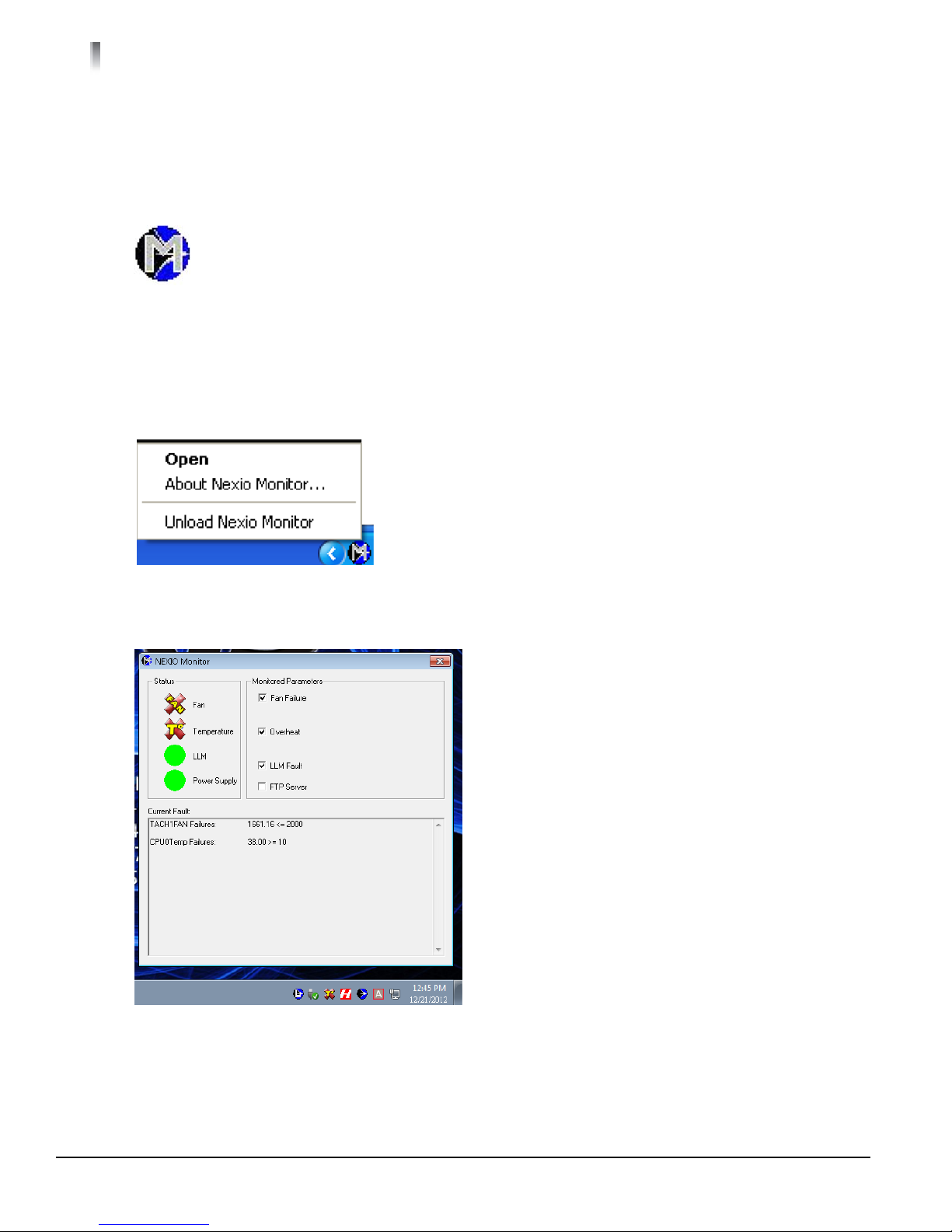
To Open NEXIO Monitor
1 Right-click on the NEXIO Monitor icon in the system tray. See Figure 5-7.
Figure 5-6 NEXIO Monitor Icon Menu
2 Click Open, the NEXIO Monitor window appears. See Figure 5-7.
Figure 5-7 NEXIO Monitor Window
175-100423-00

Selecting Monitored Diagnostics
The NEXIO Monitor lets you select which diagnostics to monitor. When a fault occurs both the Status and
the NEXIO icon will change to one of the four fault icons seen in Table 5-1:
Table 5-1. Monitored Diagnostics
Front Panel LEDs NEXIO Monitor System
Tray No
Errors
NXAMP3801HDX/HDI
NEXIO AMP Generation 6 Hardware Installation and User Guide
System
Tray
Errors
Selectable
Monitoring
Parameters
Overheat
When checked,
monitors Temperature of CPU.
Fan Failure
When checked,
monitors for a Fan
failure.
LLM Fault
When checked,
monitors LLM
function.
1,2
1,2
1,2
Function Action
Displays the current status of the CPU Temper-
ature.
Displays the current status of the Fan.
A solid green circle indicates the power supply
operating correctly, a
is
change to a red circle
indicates power supply
fault, drive problem or
drift.
Displays the current status of the LLM.
in icon indicates a critical problem due to drift
a drive problem.
or
Change
Refer to System
Cooling on
page 74.
Refer to
NXAMP3801HD
X/HDI Rear
Panel on
page 24.
Refer to the
NEXIO
Level Module
User Guide.
45
Low
1
Set by default
2
Clear diagnostic will not be monitored
FTP Server
When checked
monitors FTP
Server.
2
Only info to appear in Current Fault window.
175-100423-00

46
Chapter 5
Monitoring Your NXAMP3801HDX/HDI
LCD Keypad Buttons
The LCD Keypad arrow buttons provides system information and helps you monitor NEXIO AMP status.
Figure 5-8 LCD Keypad Arrow Buttons
The following table shows an example of the information that is displayed in each location.
For example, from the home page, if you press the right button 1 time (ending up in the 2across; 1 down
location) you will see ScabFan information as shown in Table 5-2.:
Table 5-2 LCD Display Navigation Sample
1 across 2 across 3 across 4 across
1
HARRIS
1
down
2
down
3
down
4
down
5
down
SQA-110
DOM: SQAFN Nd:110
S/N: ################
HARRIS
PlATFORM: NXAMP3810HD
DATE: 12/21/2012
Time: 2:20:19 PM
HOST: SQA-110
IP: fe80::d017:e2f3:1
SM: 0.0.0
PWS: Good
LLM NETWORK INFO
IP:
NODE: 1
DOMAIN: A
CPU 1 Temp:
CPU 2 Temp: 34.00 C
Mb1 Temp:
CPU1 FAN: 6338.03
CPU2 FAN: 6585.37
ScabFan1: 12536 RPM
ScabFan2: 13224 RPM
ScabFan3: 12365 RPM
ScabFan4: 13091 RPM
VCOREA:
VCOREB:
+5V: 5.06
5VSB:
+12V: 11.97
VBAT: 3.22
MCP55V:
1.5V: 1.47
Local Area Connectio
IP: fe80:d017:ef3:1
SM: 0.0.0.0
Local Area Connectio
IP: fe80::55c:b501:1e
SM: 0.0.0.0
Local Area Connectio
IP: fe80:145:1a61:6e
SM: 0.0.0.0
Local Area Connectio
IP: fe80:dd76:5e22:d
SM: 0.0.0.0
Local Area Connectio
IP: fe80:1511:e234:e
SM: 0.0.0.0
Server Engine Status
LLM0: 0:2580 (3721336k)
LLM1: 0 (OK)
CH1 ID: offline
CH1 IC: offline
CH2 ID: offline
CH2 IC: offline
CH3 ID: offline
CH3 IC: offline
CH4 ID: offline
CH4 IC: offline
CH5 ID: offline
CH5 IC: offline
CH6 ID: offline
CH6 IC: offline
6
down
1
Home page
175-100423-00
Local Area Connectio
IP: fe80:a907:e03:7a
SM: 0.0.0.0

System Drive Recovery
6
System Recovery
This Chapter describes the system recovery process using the system recovery image, also called the WIM
image.
47
Initial WIM Recovery Image
The initial WIM image is captured to the Harris System Recovery USB stick at the customer’s facility during
initial system deployment. At the time of shipment, the Harris System Recovery USB stick does not include a
WIM file.
Prepare the Drive for Capture
When you capture a WIM image, you are capturing the current state of the Operating System drive on the
NXAMP3801HDX/HDI system to use for future system recovery.
A WIM image capture can contain extremely large files. Before capturing the image you should delete any
log files and temporary files that are unnecessary to store as a part of the WIM image capture.
Format a Third-Party USB Stick
The WIM image must be captured to a properly formatted USB stick. It is recommended that the WIM image
is captured to the Harris System Recovery USB stick, which is already properly formatted for the WIM image.
If you are using a third-party USB stick, use the following steps to format the USB stick for the WIM image.
1 Insert the third-party USB stick into one the USB port on the back of the NXAMP3801HDX/HDI.
2 Insert your Harris USB stick into the remaining USB port on the back of the NXAMP3801HDX/HDI
3 On the NXAMP3801HDX/HDI system, open the Y:\Programs\PE_Apps folder.
4 Double-click NxImage.exe to start the NxImage application.

48
Chapter 6
System Drive Recovery
5 From the File menu, select Format Disk. The Format Disk dialog opens.
Figure 6-1 Format Disk Dialog
6 From the Assign Letter drop-down list, select only the third-party USB stick
7 From the Format Type drop-down list, select NTFS.
8 Click the FORMAT button to format the third-party USB stick.
Capture the WIM Image
Use the following steps to capture a WIM image for future system recovery.
1 Insert the Harris System Recovery USB stick into the USB port on the front or back of the NXAMP3801HDX/
HDI.
2 Restart the system.
3 Continuously press F11 during the POST to open the Boot Menu.
Figure 6-2 Boot Menu
4 Select the USB drive and press ENTER to access the Harris Recovery Desktop.
175-100423-00

NXAMP3801HDX/HDI
NEXIO AMP Generation 6 Hardware Instalation and User Guide
5 On the Harris Recovery Desktop, double-click the Harris Utility Launcher icon.
49
Figure 6-3 Harris Recovery Desktop
6 In the Harris NEXIO Utility Launcher, click the IMAGING button to open the NxImage application.
7 From the File menu, select Capture WIM Image to open the Capture Image dialog.
Figure 6-4 Capture Image Dialog
8 Click the Browse button below Step (1): Select the source drive or field to capture.
9 Select the source drive or folder to capture.
10 Select the Folder.
11 Click the Browse button below Step (2) Select the name and location for the image file.
12 Select the location and enter name from the file and click Save.
13 In the Capture Image dialog, select the Make Bootable checkbox.
175-100423-00

50
Chapter 6
System Drive Recovery
14 Click Capture Image button. The progress and status displays in the title bar.
15 When
the capture is complete, click Close.
If the final WIM image does not fit on the Harris System Recovery USB stick or the third-party USB
stick, you can capture the WIM image to a network share.
Apply the WIM Recovery Image
Use the following steps to apply a WIM image and restore your NXAMP3801HDX/HDI system to the
configuration captured by the WIM image.
1 Insert
2 Restart the system.
3 Continuously press F11 during the POST to open the Boot Menu.
Figure 6-5 Boot Menu
4 Select the USB stick and press ENTER key to access the Harris Recovery Desktop.
5 On the Harris Recovery Desktop, double-click the Harris NEXIO Utility Launcher icon.
the Harris System Recovery USB stick containing your production-ready WIM image into the USB port
on the front of the NXAMP3801HDX/HDI Server.
Figure 6-6 Harris Recovery Desktop
175-100423-00

NXAMP3801HDX/HDI
NEXIO AMP Generation 6 Hardware Instalation and User Guide
6 In the Harris NEXIO Utility Launcher, click the Imaging button to open the NxImage application.
7 From the File menu, select Format Disk to open the Format Disk dialog.
.
Make sure you know which disk you are going to format. Because there may be multiple drives
listed, care must be taken not to select the USB stick containing your WIM or any Media drives in
your NXAMP3801HDX/HDI server.
8 In the Assign Letter list, select C.
9 In the Format Type list, select NTFS.
10 Click the Format button.
11 When the formatting is complete, click Close to return to the NxImage application.
12 From the File menu, select Apply Image.
13 In the Apply Image dialog, click Open to access the Select the Source Image dialog.
51
Figure 6-7 Apply Image Dialog
14 In the Select the Source Image dialog, navigate to the Harris Recovery USB drive, open the WIM
Image folder, and then double-click the applicable .wim file.
Figure 6-8 Select the Source Image Dialog
15 The
filename displays in the Step (1): Select the source image to apply.
175-100423-00

52
Chapter 6
System Drive Recovery
16 In the Apply Image dialog, click the Browse button and select the C:\ drive. The drive displays in the Step
(2): Select the destination folder or drive to apply the image field.
You must use the Browse button to select the destination drive.
17 Click the Apply Image button. The progress and status displays in the title bar.
18 Click Close to return to the Harris Recovery Desktop.
19 Restart
the NXAMP3801HDX/HDI system.
175-100423-00

How to Create or Rebuild a
7
RAID 1 Boot Drive
Your NEXIO AMP is shipped with only one boot drive. An optional boot drive can be ordered and set up as a
mirrored drive known as RAID 1.
Creating a New RAID 1 Boot Drive
The following procedures will step you through the process of turning a single boot disk into a 2 drive
RAID 1 boot volume. These procedures are to be done only when the Server is down for maintenance.
53
1 Make sure to backup all important data before creating a new RAID 1 drive.
2 Remove the Drive 1 carrier (Removing a Hard Drive Carrier from the Chassis on page 65) and
mount the spare SSD drive on the carrier. Refer to Installing a Hard Drive into a Drive Carrier on
page 65.
3 Re-insert the spare SSD drive and carrier into its bay vertically, keeping the carrier oriented so that the
release button is on the right side. When the carrier reaches the rear of the bay, the release handle
will retract.
4 Push the hard drive into the hard drive bay until the hard drive clicks into the locked position.
5 Locate the application through the Microsoft Windows start menu and select Intel Raid Storage
enterprise.
Figure 7-1 Start menu

54
Chapter 7
How to Create or Rebuild a RAID 1 Boot Drive
6 Select Create Volume to begin the process.
Figure 7-2 Select
7 In the Create Volume window, verify that Intel(R) C600 Series chipset SATA RAID Controller is
selected.
8 Verify that Real-Time data protection
(RAID 1) under Select Volume Type is selected.
9 Click the Next button.
Figure 7-3 Configure
10 In the Name window, enter the name of the volume
11 In Select the array disks (minimum selection required):, select SATA SSD on Controller 0, Port 0
(224 GB) (System) and SATA SSD on Controller 0, Port 1 (224 GB).
12 In Do you want to keep data from one of the selected disks?, select Yes: SATA SSD on Controller 0,
Port 0.
175-100423-00

13 Click the Next button.
NXAMP3801HDX/HDI
NEXIO AMP Generation 6 Hardware Installation and User Guide
55
Figure 7-4 Confirm Volume Creation
14 Click Create Volume.
Figure 7-5 Confirm
15 In the Volume Creation Complete window, click the OK button to confirm The Volume was
Created Successfully.
175-100423-00

56
Chapter 7
How to Create or Rebuild a RAID 1 Boot Drive
16 Do not reboot your Server. The Migrating process will take 15 to 30 minutes.
Figure 7-6 Migrating Data percentage complete
17 When the migration is complete a pop-up message will appear in the tray (Figure 7-7) and the Status will
display Normal (Figure 7-8).
Figure 7-7 Tray pop-up message
Figure 7-8 Status Normal
18 You must reboot the Server.
175-100423-00

NEXIO AMP Generation 6 Hardware Installation and User Guide
Rebuilding a RAID 1 Boot Drive
1 An Icon in the tray (Figure 7-9) show an error.
Figure 7-9 Drive error
2 Locate the application through the Microsoft Windows start menu and select Intel Raid Storage
enterprise.
NXAMP3801HDX/HDI
57
Figure 7-10 All Programs
3 Under Devices, an Unknown disk drive is identified.
Figure 7-11 Status Reporting Error
175-100423-00

58
Chapter 7
How to Create or Rebuild a RAID 1 Boot Drive
4 Install your new hard drive into a carrier. Refer to
5 Under Volume Properties window, click on Rebuild to another disk
6 In the Intel Raid Storage Technology enterprise window, Under Devices window, select Unknown
disk (0 GB).
Figure 7-12 Rebuild Volume
7 In the Rebuild Volume window, click the radio button to select SATA SSD on Controller 0, Port 1
(224 GB).
8 Click the Rebuild button.
Figure 7-13 Current Status Message
175-100423-00

NXAMP3801HDX/HDI
NEXIO AMP Generation 6 Hardware Installation and User Guide
9 In the Intel Rapid Storage enterprise window, after the rebuild process has been completed, the
unknown drive will no longer be displayed.
Figure 7-14 Status Functioning Normal
10 When completed, click on the close button.
59
175-100423-00

60
Chapter 7
How to Create or Rebuild a RAID 1 Boot Drive
175-100423-00

Maintenance
8
This chapter provides safety guidelines, tools and access information about maintaining your
NXAMP3801HDX/HDI system.
Installation Tools
You will need the following tools for the safe and proper installation of your system.
Phillips screw driver
Anti-static strap
Small tip screwdriver
61
Important Safety Guidelines
The NXAMP3801HDX/HDI should only be accessed and serviced by technically qualified
personnel or technicians.
1 Turn off all peripheral devices and the power supply connected to the system.
2 Unplug all power cords from the system or wall outlets.
3 Disconnect all the cables and label the cables for easy identification.
4 Use a grounded wrist strap designed to prevent static discharge when handling components.
Chassis Cover
Removal
Figure 8-1 Main Power Switch Location

62
Chapter 8
Maintenance
1 Press the power off button on the front panel (Figure 8-1 on page 61) for 5 seconds to remove the power
supply to the system.
2 Unplug both power cords from the system or wall outlets to remove the standby power to the system.
3 If necessary, label and disconnect all remaining cables to the NXAMP3801HDX/HDI.
4 Use a grounded wrist strap designed to prevent static discharge when handling components.
Figure 8-2 Knurled captive screws
5 Loosen
and slide the cover backwards and off the chassis.
the two knurled captive panel screws on the back of the NXAMP3801HDX/HDI (see Figure 8-2)
Replacement
1 To replace the cover on the chassis:
a Side the cover forward toward the front of the chassis.
b Secure with the two knurled captive screws (see Figure 8-2).
2 Reconnect any cables removed during the chassis cover Removal on page 61.
Replacing the Onboard CR2032 Battery
The battery on your motherboard may be old. Check to verify that it still supplies ~3VDC, if not:
1 To gain access to the CMOS battery, refer to Chassis Cover on page 61.
2 Refer to Figure 8-3 on page 63 for battery location.
3 When replacing the onboard battery make sure to handle the used battery carefully. Do
not damage the battery in any way; a damaged battery may release hazardous
materials into the environment.
4 Using only a CR2032 CMOS battery, install the onboard battery per Figure 8-4 on
page 63, upside down to avoid possible explosion.
5 Please comply with the regulations set up by your local hazardous waste management
agency to dispose of your used battery properly.
6 Slide the chassis cover back onto the chassis and secure with the two knurled captive
screws.
7 Reconnect all marked cables and power cords.
8 Press the power on button on the front panel (Figure 8-1 on page 61) for 5 seconds.
9 Press DEL to go to the BIOS setup screen.
10 If your CMOS settings have been lost, go to AMI BIOS Recovery on page 67.
175-100423-00

NXAMP3801HDX/HDI
NEXIO AMP Generation 6 Hardware Installation and User Guide
63
Figure 8-3 CR2032 battery location
Figure 8-4 Battery replacement direction
Hot Swap Power Supplies
Your system uses a dual-redundant hot-swappable power supply modules. These power supplies are
auto-switching capable and operate at a 100v to 240v input voltage. An illuminated green light indicates
that the power supply module is operating, a failed power supply module LED will not be illuminated.
You can replace a failed power supply module without turning the system off.
Make sure you have a replacement power supply module before starting this procedure. Keep a replacement
power supply module on hand, and replace failed modules promptly. Running on one power supply module
for any To turn off the alarm and unplug the power supply module from the system.
For redundant operation your system requires two working modules. If one module fails, replace
the failed module immediately.
175-100423-00

64
Chapter 8
Maintenance
Replacing a Power Supply Module
Unplug the power cord before removing the power supply module.
1 Look at the status LED on each plug-in power supply module (Figure 8-5). The LED on the failed power
supply module will not be illuminated.
Figure 8-5 Power Supply Module
2 To remove a plug-in power supply module:
a Unplug the AC power cord only to the failed plug-in power supply module.
b Push the release tab to the left.
c Holding the release tab, grasp the power supply module handle and pull the power supply module
out of the frame.
3 To replace a plug-in power supply module:
a Slide the replacement plug-in power supply module into the empty slot.
b Press firmly so that it clicks in place.
c Plug-in the AC power cord, the module's status LED will illuminate.
175-100423-00

NEXIO AMP Generation 6 Hardware Installation and User Guide
Hard Drive Removal or Replacement
The NXAMP3801HDX/HDI comes equipped with hot-swappable hard drives. Only Harris Broadcast qualified
hard disk drives are for use in NXAMP3801HDX/HDI chassis.
CAUTION- Regardless of how many hard drives are installed, all drive carriers must remain in the
drive bays to maintain airflow.
Removing a Hard Drive Carrier from the Chassis
NXAMP3801HDX/HDI
65
Figure 8-6 Carrier release locations
1 Press the drive release button. See Figure 8-6.
2 Swing the handle out fully.
3 Pull the carrier straight out.
Installing a Hard Drive into a Drive Carrier
1 Remove the carrier from the NXAMP3801HDX/HDI. Refer to Removing a Hard Drive Carrier from the
Chassis on page 65.
2 Insert your new drive into the carrier with the PCB side facing down and the connector end toward
the rear of the carrier.
3 Align the drive in the carrier so that the mounting holes of both are aligned. Refer to Figure 8-7 on
page 66.
175-100423-00

66
Chapter 8
Maintenance
4 Secure the drive to the carrier with four M3 flat-head screws included in the HDD bag of your accessory
box.
Figure 8-7 Drive Tray with SSD or Spinner.
5 Insert the drive and drive carrier into its bay vertically, keeping the carrier oriented so that the release
button is on the right side. When the carrier reaches the rear of the bay, the release handle will retract.
6 Push the hard drive into the hard drive bay until the hard drive clicks into the locked position.
Replacing a RAID 1 Boot Drive
If a boot drive is bad, a message appears indicating that there is a RAID Access Failure. Refer to Figure 8-8.
Figure 8-8 Drive error
Do the following:
a Step 1 on page 65 thru Step 6. Refer to Hard Drive Removal or Replacement on page 65.
b Continue on Step 1 on page 57 thru Step 10 on page 59. Refer to Rebuilding a RAID 1 Boot
Drive on page 57.
175-100423-00

NEXIO AMP Generation 6 Hardware Installation and User Guide
Replacing Media Drive - HDI Only
This section provides information on replacing a media drive. Detailed information is provided in the NEXIO
LOW LEVEL MODULE USER GUIDE. There is usually no need to stop the LLM to replace the media drive. It
is recommended that the system is running throughout the replacement process.
1 Refer to Figure 8-9 to identify the media drive. Drive numbers shown in red.
2 For removal and replacement of a media drive, refer to Hard Drive Removal or Replacement on
page 65.
NXAMP3801HDX/HDI
67
Figure 8-9 NXAMP3801HDI Front Panel Showing Media Drives
3 Follow the instructions in the NEXIO Low Level Module User Guide.
AMI BIOS Recovery
WARNING: Do not upgrade the BIOS unless your system has a BIOS-related issue. Flashing the
wrong BIOS can cause irreparable damage to your system. If you need to update the BIOS, do
not shut down or reset the system while the BIOS is updating to avoid possible boot failure.
1 Insert the Harris supplied USB stick that contains the new BIOS binary image and power the system
down.
2 Press the main power switch (Figure 8-1 on page 61) on the front panel of the NXAMP3801HDX/HDI
and press and hold <Ctrl> and <Home> simultaneously on your keyboard until the USB device's LED
indicator comes on. This will take a few seconds or up to one minute.
3 Once the USB device's LED is on, release the <Ctrl> and <Home> keys. The system may generate
beep codes to indicate that the BIOS ROM firmware is being updated. The screen will also display a
message as shown below:
DO NOT INTERRUPT THIS PROCESS
4 When the Boot Sector Recovery Process is complete, the system will reboot automatically.
5 When DOS prompt appear, please type AMI.BAT BIOSname.###.
6 Do not interrupt the process until the flashing is complete.
175-100423-00

68
Chapter 8
Maintenance
7 After you see the message of BIOS has completed the update:
a Press
a Unplug
and hold the power off button (Figure 8-1 on page 61) for 5 seconds.
the two power cords from the redundant power supplies.
b Use a grounded wrist strap designed to prevent static discharge when handling components.
c Loosen
the two knurled captive panel screws on the back of the NXAMP3801HDX/HDI (Figure 8-2
on page 62) and slide the cover backwards toward the rear of the chassis.
d Lift
the cover up and off the chassis.
Figure 8-10 JBT1 CMOS Clear Pad
e Remove the onboard CMOS battery (refer to Figure 8-4 on page 63) before you short JBT1 to
clear the CMOS.
f Clear the CMOS by shorting the CMOS pads JBT1 (Figure 8-10) with a small tip screwdriver.
g Remove the screwdriver.
h Replace the CMOS battery (Refer to Figure 8-4 on page 63).
8 Reconnect the two power cords to the redundant power supplies and press the power on button
(Figure 8-1 on page 61) on the front panel for 5 seconds.
9 Press DEL to go to the BIOS setup screen.
10 Press F3 to load the default.
11 Go to Save & Exit>Restore Optimized Defaults. Press Enter.
12 Advanced>CPU Configuration:
Hyper Threading = Disabled
Intel Virtualization = Disabled
175-100423-00

13 Advanced>CPU Configuration>CPU Power Management Configuration:
Power Technology = Disabled
Energy/Performance Bias = Disabled
14 Advance>SATA Configuration
SATA Mode = RAID Mode
15 Advanced>PCLe/PCI/PnP Configuration
Load Onboard Lan 1 = Disabled
Load Onboard LAN 2 = Disabled
Video Priority = OFF BOARD
16 Press F4 to save and exit.
17 To replace the cover on the chassis:
a Side the cover forward toward the front of the chassis.
b Secure with the two knurled captive screws.
Fan Replacement
1 Remove the chassis cover. Refer to Chassis Cover on page 61
2 Carefully lift the defective fan up and away from the chassis frame. Refer to Figure 8-11.
NXAMP3801HDX/HDI
NEXIO AMP Generation 6 Hardware Installation and User Guide
69
Figure 8-11 Fan location
175-100423-00

70
Chapter 8
Maintenance
3 Facing the front of the NXAMP3801:
a With
the Fan connector on your right side (Figure 8-12) and facing down, Insert the new fan
(Harris Broadcast part number 131-100005Q00) into the three slots shown identified in
Figure 8-13.
Figure 8-12 Standalone fan
b Carefully push down to lock the fan into position per Figure 8-11 on page 69.
Figure 8-13 Fan mounting slots
4 To replace the cover on the chassis:
a Side the cover forward toward the front of the chassis.
b Secure with the two knurled captive screws.
5 Reconnect any cables removed in chassis cover Removal on page 61.
175-100423-00

NXAMP3801HDX/HDI
NEXIO AMP Generation 6 Hardware Installation and User Guide
71
175-100423-00

72
Chapter 8
Maintenance
175-100423-00

Troubleshooting
9
This chapter provides information about BIOS error beep codes, power supply modules and drive failures.
BIOS Error Beep Codes
During the POST (Power-On Self-Test) routines, which are performed each time the system is powered on,
errors may occur.
73
Non-fatal errors
Are those which, in most cases, allow the system to continue the boot-up process. The error messages
normally appear on the screen.
Fatal errors
Are those which will not allow the system to continue the boot-up procedure. If a fatal error occurs, you
should consult with BCD Technical Support. Refer to the Regional Service Contact Information on
page 2.
These fatal errors are usually communicated through a series of audible beeps found in Table 9-1. The
numbers on the fatal error list correspond to the number of beeps for the corresponding error.
Table 9-1. BIOS Error Beep Codes
Beep Code Error Message Description
1 beep Refresh Circuits have been reset (Ready to power up)
beeps and 1 long beep Memory error No memory detected in the system
5 short
5 beeps No Con-In or Con-Out
devices
Control-in includes:
USB or PS/2 keyboard
PCI or Serial console redirection
IPMI KVM or SOL
1 Continuous beep System OH
Control-out includes:
video controller
PCI or Serial console redirection
IPMI SOL.
System Overheat. Refer to
Contact Information on page 2.
Regional Service

74
Chapter 9
Troubleshooting
Power Supply Module Failure
If a failure occurs with one of the redundant power supply modules, an alarm is generated. It is essential that
both power supply modules be connected at all times, therefore it is recommended that the failed module be
replaced immediately to maintain full power redundancy.
Table 9-2 Power Supply LED and Alarm Descriptions
LED Color Alarm Description Action
Amber System is off and plugged in. None
Off No AC power to the System, Check facilities power
Sounds Power supply module failure Replace power supply module, see Replacing the Onboard
CR2032 Battery on
System Cooling
If your NEXIO Monitor, system tray displays or and the LCD front panel TEMP or FAN displays
red, go to step 1.
.
page 62
1 Using a grounded wrist strap designed to prevent static discharge when handling components, loosen
the two knurled captive panel screws on the back of the NEXIO VOLT and slide the cover backwards
toward the rear of the chassis.
2 Lift the cover up and off the chassis
3 Check system cooling to make sure that all heatsink fans, and CPU/system fans, etc., are work
properly.
a To replace a defective fan (Harris Broadcast part number 131-100005Q00), refer to Fan
Replacement on page 69.
b If any other system cooling problems are found, contact Harris tech support. Refer to Regional
Service Contact Information on page 2.
CMOS Battery
The CMOS is found onboard your motherboard that hold a small bit of code which helps the
NXAMP3801HDX/HDI boot up in Windows. If the NXAMP3801HDX/HDI starts losing its date and time
settings, you can be sure your CMOS battery is running out of power. If it is not changed out soon you will
eventually get to a point where the NXAMP3801HDX/HDI cannot find its own hard drives during a reboot
and you may see the blue screen flash up with an error that says Unmountable_boot_Volume. Refer to
Replacing the Onboard CR2032 Battery on page 62.
175-100423-00
 Loading...