


Delivering the Moment
Installaon and Operaon Manual
Neo® NSM-8×1AES/NSM-7×2AES
Serial Digital Audio Roung Switchers
Edion D
NSM-8X1AES MAN

Publicaon Informaon
© 2014 Imagine Communicaons Corp. Proprietary and Condenal.
Imagine Communicaons considers this document and its contents to be proprietary and condenal. Except for
making a reasonable number of copies for your own internal use, you may not reproduce this publicaon, or any part
thereof, in any form, by any method, for any purpose, or in any language other than English without the wrien consent
of Imagine Communicaons. All others uses are illegal.
This publicaon is designed to assist in the use of the product as it exists on the date of publicaon of this manual, and
may not reect the product at the current me or an unknown me in the future. This publicaon does not in any way
warrant descripon accuracy or guarantee the use for the product to which it refers. Imagine Communicaons reserves
the right, without noce to make such changes in equipment, design, specicaons, components, or documentaon as
progress may warrant to improve the performance of the product.
Trademarks
6800+™, ADC™, CCS Navigator™, Channel ONE™, ChannelView™, ClipSync™, Delay™, D Series™, D Series DSX™, Deliver
the Moment™, Delivering the Moment™, FAME™, Farad™, G8™, G Scribe™, HView™, IconMaster™, IconLogo™, IconSta
-
on™, IconKey™, InfoCaster™, InfoCaster Creator™, InfoCaster Manager™, InfoCaster Player™, InstantOnline™, Invenio®,
Live Update™, mCAPTURE™, Magellan™, Magellan CCS Navigator™, Magellan Q SEE™, MulService SDN™, NetPlus™,
NetVX™, NewsForce™, Nexio® G8™, Nexio AMP® ChannelView™, Nexio® Channel ONE™, Nexio® ClipSync™, Nexio®
Delay™, Nexio® Digital Turnaround Processor™, Nexio® Farad™, Nexio® G Scribe™, Nexio® IconKey™, Nexio® IconLogo™,
Nexio® IconMaster™, Nexio® IconStaon™, Nexio® InfoCaster™, Nexio® InfoCaster Creator™, Nexio® InfoCaster Manag
-
er™, Nexio® InfoCaster Player™, Nexio® InfoCaster Trac™, Nexio® InstantOnline™, Nexio® mCAPTURE™, Nexio® NewsForce™, Nexio® NXIQ™, Nexio® Playlist™, Nexio® Remote™, Nexio®RTX Net™, Nexio® TitleMoon™, Nexio® TitleOne™,
Nexio® Velocity ESX™, Nexio® Velocity PRX™, Nexio® Velocity XNG™, Nexio® Volt™, OPTO+™, Panacea™, Planum™,
Playlist™, Predator II GRF™, Predator II GX™, Punctuate™, Remote™, RTX Net™, QuiC™, Q SEE™, SD STAR™, Selenio™,
Selenio 6800+™, SelenioNext™, Selenio X50™, Selenio X85™, Selenio X100™, TitleMoon™, TitleOne™, Velocity ESX™,
Velocity PRX™, Velocity XNG™, Versio™, Videotek® SD STAR™, X50™, and X85™ are trademarks of Imagine Communica
-
ons or its subsidiaries.
Altude Express®, Connectus®, Enabling PersonalizedTV®, ICE® Broadcast System, ICE Illustrate®, ICE Q® algorithms, ICE
-
PAC®, Imagine ICE®, Inscriber®, Inscriber® Connectus®, Invenio®, NEO®, Nexio®, Nexio AMP®, PersonalizedTV®, RouterWorks®, Videotek®, Videotek® ASI STAR®, Videotek® GEN STAR®, and Videotek® HD STAR® are registered trademarks of
Imagine Communicaons or its subsidiaries.
Microso® and Windows® are registered trademarks of Microso Corporaon. HD BNC is a trademark of Amphenol
Corporaon. Some products are manufactured under license from Dolby Laboratories. Dolby and the double D symbol
are registered trademarks of Dolby Laboratories. DTS Neural audio products are manufactured under license from DTS
Licensing Limited. DTS and the Symbol are registered trademarks & the DTS Logos are trademarks of DTS, Inc. © 2008
2010 DTS, Inc. All other trademarks and trade names are the property of their respecve companies.
Contact Informaon
Imagine Communicaons has oce locaons around the world. For locaons and contact informaon see:
hp://www.imaginecommunicaons.com/contact us/
Support Contact Informaon
For support contact informaon see:
▪ Support Contacts: hp://www.imaginecommunicaons.com/services/technical support/
▪ eCustomer Portal: hp://support.imaginecommunicaons.com
© 2014 Imagine Communicaons Corp. Proprietary and Condenal

Preliminary—Contents are proprietary and confidential. Do not photocopy or distribute.
NEO
NSM-8×1AES and NSM-7×2AES
Serial Digital Audio
Routing Switchers
Installation and Operation Manual
This text is here to serve as a "place holder" to force printing of a blank page.
Editi
on
D
A
ugust 2006

NSM-8×1AES/NSM-7×2AES Installation and Operation Manual v
Preliminary—Contents are proprietary and confidential. Do not photocopy or distribute.
Contents
Preface
Manual Information ................................................................................ ix
Purpose............................................................................................. ix
Audience .......................................................................................... ix
Revision History .............................................................................. ix
Writing Conventions..........................................................................x
Obtaining Documents ...................................................................... xi
Unpacking the Module............................................................................ xi
Safety Standards and Compliances ........................................................ xii
Safety Terms and Symbols ............................................................. xii
Restriction on Hazardous Substances (RoHS) Directive .............. xiii
Waste from Electrical and Electronic Equipment
(WEEE) Directive ......................................................................... xiv
Chapter 1: Introduction
Overview...................................................................................................1
Product Description ..................................................................................2
Main Features ...................................................................................2
Backup Switching .............................................................................3
Switch Algorithm/Method ................................................................4
Applications ..............................................................................................5
Major Components ...................................................................................6
AES Digital Audio Main Switch Module .........................................7
AES Digital Audio Back Input/Output Modules ..............................8
Functional Block Diagram .....................................................................11

vi NSM-8×1AES/NSM-7×2AES Installation and Operation Manual
Preliminary—Contents are proprietary and confidential. Do not photocopy or distribute.
Contents
Chapter 2: Installation and Removal
Overview ................................................................................................ 13
Packing List ........................................................................................... 14
Installing NSM-8×1AES/NSM-7×2AES Modules ................................ 14
Removing NSM-8×1AES/NSM-7×2AES Modules .............................. 14
Upgrading NSM-8×1AES/NSM-7×2AES Firmware ............................ 14
Upgrading the Firmware (Discovery Method) ............................... 15
Upgrading the Firmware (Drag-and-Drop Method) ...................... 16
Correcting a Failed Upgrading Procedure ............................................. 19
Setting the Module to Fail-Safe Loader Mode ............................... 19
Upgrading the Firmware in Fail-Safe Mode .................................. 19
Rebooting the Module .................................................................... 21
Chapter 3: Operation
Overview ................................................................................................ 23
Operation Notes ..................................................................................... 24
Cross-Functional Parameter Changes ................................................... 25
Navigating the Operator and All Lists .................................................. 26
Operator and All List Parameters .......................................................... 27
NSM-8×1 AES ............................................................................... 28
NSM-7×2AES ................................................................................ 32
Setup Parameters ................................................................................... 36
Alarms ................................................................................................... 37
Alarm Synchronization .................................................................. 37
Identifying the Cause of an Alarm ................................................. 37
Enabling or Disabling an Alarm Parameter ................................... 37
Restoring Alarm Default Settings .................................................. 38
State Recovery Parameter Availability .................................................. 39
LEDs and Module Indicators ................................................................. 39
General Information ....................................................................... 39
Card-Edge Locations ...................................................................... 40
LED Descriptions ........................................................................... 41
Module Indicator Descriptions ....................................................... 41

NSM-8×1AES/NSM-7×2AES Installation and Operation Manual vii
Contents
Preliminary—Contents are proprietary and confidential. Do not photocopy or distribute.
Chapter 4: Specifications
Overview.................................................................................................43
Inputs ......................................................................................................44
Outputs ...................................................................................................45
Performance ...........................................................................................46
Power Consumption................................................................................46
Temperature ............................................................................................46
Appendix A: Tree View Navigation
Overview.................................................................................................47
Navigating the Tree View ......................................................................48
Tree View Parameters ............................................................................49
NSM-8×1AES Tree View ...............................................................49
NSM-7x2AES Tree View ...............................................................53
Appendix B: Resource Module X-Y Network
Communication
Overview.................................................................................................57
Network Connectivity ............................................................................58
X-Y (LCN) Port ..............................................................................58
X-Y-TCP/IP Support ......................................................................60
Connecting the Frame ............................................................................61
Including the NSM Router(s) in the RouterMapper Database ...............62
Setting Up a Serial Connection .......................................................62
Transferring Router Information (Serial Connection) ....................62
Setting Up an Ethernet Connection ................................................63
Transferring Router Information (Ethernet Connection) ................63
Supported Features and X-Y Commands ...............................................65
Router Control Features ..................................................................65
X-Y Commands for Crosspoint Status ...........................................65
X-Y Commands for Crosspoint Control .........................................66
X-Y Commands for Lock/Protect Control and Status ....................74
Index
Keywords ...............................................................................................77

viii NSM-8×1AES/NSM-7×2AES Installation and Operation Manual
Preliminary—Contents are proprietary and confidential. Do not photocopy or distribute.
Contents

NSM-8×1AES/NSM-7×2AES Installation and Operation Manual ix
Preliminary—Contents are proprietary and confidential. Do not photocopy or distribute.
Preface
Manual Information
Purpose
This manual details the features, installation, operation, maintenance,
and specifications of the NEO™ NSM-8×1AES and NSM-7×2AES
serial digital audio routing switchers.
Audience
This manual is written for technicians and operators responsible for the
installation, setup, maintenance, and operation of the NSM-8×1AES
and NSM-7×2AES serial digital audio routing switchers.
Revision History
Table P-1. Revision History of Manual
Edition Date Revision History
A July 2002 Initial release
B December 2004 Added resource module X-Y
network communication
information
C February 2005 Updated Operator List, All
List, and Tree View List
D August 2006 Added RoHS and WEEE
compliance information

x NSM-8×1AES/NSM-7×2AES Installation and Operation Manual
Preliminary—Contents are proprietary and confidential. Do not photocopy or distribute.
Preface
Writing Conventions
To enhance your understanding, the authors of this manual have
adhered to the following text conventions:
Table P-2. Writing Conventions
Term or Convention Description
Bold Indicates dialog box, property sheet, field,
button, check box, list box, combo box,
menu, submenu, window, list, and selection
name
Italics Indicates email addresses, names of books
and publications, and first instances of new
terms and specialized words that need
emphasis
CAPS Indicates a specific key on the keyboard,
such as ENTER, TAB, CTRL, ALT,
DELETE
Code Indicates variables or command-line
entries, such as a DOS entry or something
you type into a field
> Indicates the direction of navigation
through a hierarchy of menus and windows
hyperlink Indicates a jump to another location within
the electronic document or elsewhere
Internet address
Indicates a jump to a Web site or URL
Note
Indicates important information that helps
to avoid and troubleshoot problems

NSM-8×1AES/NSM-7×2AES Installation and Operation Manual xi
Preface
Preliminary—Contents are proprietary and confidential. Do not photocopy or distribute.
Obtaining Documents
Installation, navigation, configuration, and setup information is now
included in the NEO FR-3901, FR-3903, and FR-3923 Mounting
Frames Installation and Operation Manual. If your current NEO frame
manual is Edition A, B, C, or D, you will need to download an updated
version from our Web site to access this information.
Technical documents can be viewed or downloaded from our Web site
at www.broadcast.harris.com/leitch
(go to Support>Documentation).
Alternatively, contact your Customer Service representative to request a
document.
Unpacking the Module
Before you install and configure NEO modules, follow these steps:
1. Check the equipment for any visible damage that may have
occurred during transit.
2. Make sure that you have received all items listed on the packing
list.
3. Remove the anti-static shipping pouch, if present, and all other
packaging material.
4. Save the original packaging materials for possible reuse.
5. Contact your Sales representative if parts are missing or damaged.
Keep at least one set of original packaging in the event that a product
needs to be returned for service. If the original package is not available,
you can supply your own packaging as long as it meets the following
criteria:
• The packaging must be able to withstand the product’s weight.
• The product must be held rigid within the packaging.
• There must be at least two in. (five cm) of space between the
product and the container.
• The corners of the product must be protected.
If the product is still within the warranty period, we will return it to you
by prepaid shipment after servicing.
xii NSM-8×1AES/NSM-7×2AES Installation and Operation Manual
Preliminary—Contents are proprietary and confidential. Do not photocopy or distribute.
Preface
Safety Standards and Compliances
See the NEO Safety Instructions and Standards Manual to find the
safety standards and compliances for this NEO series product. A safety
manual is shipped with every FR-3901, FR-3903, and FR-3923
Mounting Frames Installation and Operation Manual and can be
downloaded from ourWeb site at www.broadcast.harris.com/leitch
.
Alternatively, contact your Customer Service representative for a copy
of this safety manual.
Safety Terms and Symbols
This manual uses the following safety terms and symbols. See your
NEO Safety Instructions and Precautions Guide for more information.
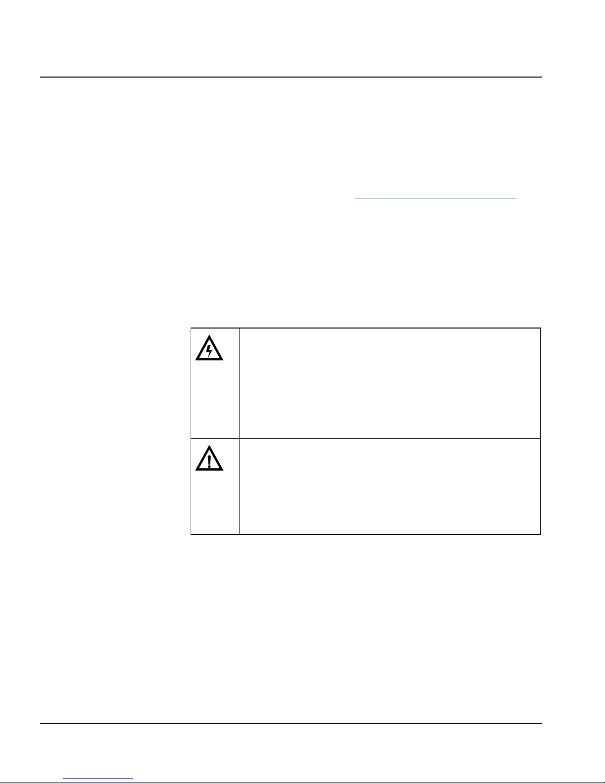
Table P-3. Safety Terms and Symbols Used in Manual
WARNING
Statements identifying conditions or practices
that can result in personal injury or loss of life:
High voltage is present. Uninsulated dangerous
voltage within the product’s enclosure may be
sufficient to constitute a risk of electric shock to
persons.
CAUTION:
Statements identifying conditions or practices
that can result in damage to the equipment or
other property: Important operating and
maintenance (servicing) instructions in the
literature accompanying the product.

NSM-8×1AES/NSM-7×2AES Installation and Operation Manual xiii
Preface
Preliminary—Contents are proprietary and confidential. Do not photocopy or distribute.
Restriction on Hazardous Substances (RoHS) Directive
Directive 2002/95/EC—commonly known as the European Union (EU)
Restriction on Hazardous Substances (RoHS)—sets limits on the use of
certain substances found in electrical and electronic equipment. The
intent of this legislation is to reduce the amount of hazardous chemicals
that may leach out of landfill sites or otherwise contaminate the
environment during end-of-life recycling. The Directive takes effect on
July 1, 2006, and it refers to the following hazardous substances:
• Lead (Pb)
• Mercury (Hg)
• Cadmium (Cd)
• Hexavalent Chromium (Cr-V1)
• Polybrominated Biphenyls (PBB)
• Polybrominated Diphenyl Ethers (PBDE)
In accordance with this EU Directive, all products sold in the European
Union will be fully RoHS-compliant and “lead-free.” (See our Web site,
www.broadcast.harris.com/leitch
, for more information on dates and
deadlines for compliance.) Spare parts supplied for the repair and
upgrade of equipment sold before July 1, 2006 are exempt from the
legislation. Equipment that complies with the EU directive will be
marked with a RoHS-compliant symbol, as shown in Figure P-1.
Figure P-1. RoHS Compliance Symbol

xiv NSM-8×1AES/NSM-7×2AES Installation and Operation Manual
Preliminary—Contents are proprietary and confidential. Do not photocopy or distribute.
Preface
Waste from Electrical and Electronic Equipment
(WEEE) Directive
The European Union (EU) Directive 2002/96/EC on Waste from
Electrical and Electronic Equipment (WEEE) deals with the collection,
treatment, recovery, and recycling of electrical and electronic waste
products. The objective of the WEEE Directive is to assign the
responsibility for the disposal of associated hazardous waste to either
the producers or users of these products. Effective August 13, 2005,
producers or users will be required to recycle electrical and electronic
equipment at end of its useful life, and must not dispose of the
equipment in landfills or by using other unapproved methods. (Some
EU member states may have different deadlines.)
In accordance with this EU Directive, companies selling electric or
electronic devices in the EU will affix labels indicating that such
products must be properly recycled. (See our Web site,
www.broadcast.harris.com/leitch
, for more information on dates and
deadlines for compliance.) Contact your local sales representative for
information on returning these products for recycling. Equipment that
complies with the EU directive will be marked with a WEEE-compliant
symbol, as shown in Figure P-2.
Figure P-2. WEEE Compliance Symbol

NSM-8×1AES/NSM-7×2AES Installation and Operation Manual 1
Preliminary—Contents are proprietary and confidential. Do not photocopy or distribute.
Chapter 1
Introduction
Overview
NSM-8×1AES and NSM-7×2 AES modules are high definition and
standard definition wideband video routing switchers designed for NEO
1RU and 3RU rack-mounted frames. This chapter covers the following
topics:
• “Applications” on page 5
• “Functional Block Diagram” on page 11
• “Main Features” on page 2
• “Major Components” on page 6
• “Product Description” on page 2
See the FR-3901 and FR-3903 Installation and Operation Manual for
information about NEO frames. The frame manual includes information
about these items:
• General information about module unpacking, installation,
removal, navigation, configuration, and setup
• Card-edge screen savers
• State recovery parameters
•Fan modules
• Resource modules
• Alarm interconnect modules
• Power supplies
• Genesis adapters
• Servicing instructions
Note
Installation, navigation, configuration, and setup information is
now included in the NEO
FR-3901, FR-3903, and
FR-3923 Mounting Frames
Installation and Operation
Manual. If your current NEO
frame manual is Edition A, B,
C, or D, you should download
an updated version from our
Web site at www.broadcast.har-
ris.com/leitch to access this
information.

2 NSM-8×1AES/NSM-7×2AES Installation and Operation Manual
Preliminary—Contents are proprietary and confidential. Do not photocopy or distribute.
Chapter 1: Introduction
Product Description
The new NEO NSM-8×1AES/NSM-7×2AES serial digital video
routing switcher series is a modular system, which features high-level
remote control capabilities and a multi-functional 1RU or 3 RU
mounting frame into which a wide range of routing (and signal
processing/interface) modules can be installed. Other complementary
signal formats, such analog video, HD/SDI, and analog audio, will be
included in the NEO platform in order to complement the NEO AES
audio switch. Module sizes include 8×1 and 7×2 with auto-switch
capabilities. HD, digital, and analog audio/video modules can be
installed within the same frame. Multiple frames can be combined to
build complex, multi-level routing systems using Blue
3
Technology the Leitch/Harris Dynamic Routing Fabric. This module, as is the case
with all modules in the NEO family, can be controlled locally via a
front-edge display or from a remote location.
Main Features
The NEO NSM-8×1AES/NSM-7×2AES series encompasses an entirely
new family of routing switchers designed to add a new tier of digital
audio routing matrices to our already strong routing product portfolio.
The NEO NSM series has additional control and functionality above
and beyond the limitations of our other small routing families.
These are the main features of the NSM-8×1AES/NSM-7×2AES serial
digital audio routing switcher:
• Provides high quality AES audio routing with enhanced control and
monitoring capabilities.
• Includes the following matrix configurations:
•8×1
•7×2
• 8×1 with automatic backup
• Supports these signal types:
• AES3
• 30kHz – 100kHz frame rates in asynchronous mode
• 32Hz, 44.1 Hz, 48kHz in synchronous mode
• Any 50% duty cycle digital signal within the voltage and
frequency range

NSM-8×1AES/NSM-7×2AES Installation and Operation Manual 3
Chapter 1: Introduction
Preliminary—Contents are proprietary and confidential. Do not photocopy or distribute.
• Allows relay bypass
• Includes synchronous or asynchronous switching
• Accepts NTSC/PAL/AES references for switching
• Allows “mix and match” of signal types in the same frame
• Provides BOS/CCS Pilot™ integrated control capabilities:
• System discovery / diagnostics – SNMP
• Remote control – Ethernet
• Remote monitoring and configuration
• Provides control via local panel, RS-232/RS-422, X-Y, or
IP/Ethernet
• Allows signal processing (A/D, D/A, frame synchronizers,
distribution amplifiers, etc.) functions and matrix routing can be
mixed in the same frame
Backup Switching
During the course of everyday events in a television facility, unexpected
circumstances will occur. Although undesirable, these circumstances do
not have to be catastrophic. With the new NEO series of professional
audio and video routers, the occurrence of such an event will be
manageable. While they cannot protect against every undesirable
condition, the NEO series of routers are designed to provide a backup
for some of the more common situations. Two such conditions are loss
of signal and loss of power. In the event of a signal loss to an individual
input or the disruption of power to a single card or an entire frame, NEO
routers can automatically switch to a predetermined source, thereby
allowing you time to evaluate and correct the fault condition.
By use of the front-edge control or remote communications you can
configure the NSM-8×1AES to either automatically switch upon
detection of signal failure, or manually switch to the desired source.
The switching can be controlled locally by using front edge control or
remotely by using our Command and Control System (CCS).

4 NSM-8×1AES/NSM-7×2AES Installation and Operation Manual
Preliminary—Contents are proprietary and confidential. Do not photocopy or distribute.
Chapter 1: Introduction
The NSM-8×1AES is configurable as an 8×1 with auto switch-over to
Input 1 if any of the inputs experience excessive errors or loss of signal.
The NSM-8×1AES/NSM-7×2AES monitors all inputs for coding errors
in the AES stream, which is known as biphase encoding errors. The
module also monitors all inputs for deterioration of the “eye pattern”
caused by transmission path effects, which is known as confidence
errors. If excessive biphase or confidence errors occur, or if the signal is
lost entirely, a signal presence error is reported for that input.
Switch Algorithm/Method
The NSM-8×1AES can operate manually or with one dedicated
automatic backup. The NSM-8×1AES router can be configured with
back-up functionality and operated in one of three modes of operation:
manual, return auto, and non-return auto.
•In manual mode (NSM-8×1AES/NSM-7×2AES), you must switch
the router to the desired source regardless of signal presence. This
mode of operation is typical of other Leitch/Harris legacy routers.
There will be no automatic switching unless power is removed.
During a “No Power” condition, the signal on Input 1 will be routed
to the output. The router will return to the previous state upon
power restoration.
•In return auto mode (NSM-8×1AES only), the router will
automatically switch to Input 1 if a signal presence error is detected
on the currently selected input. If the currently selected input is
Input 1 and it loses the signal, the output will be muted. If the signal
returns, the router will automatically switch back to its previous
source. The switch executes regardless of the signal presence status
on Input 1.
•In non-return auto mode (NSM-8×1AES only), the router will
automatically switch to Input 1 if a signal presence error is detected
on the currently selected input. If the currently selected input is
Input 1 and it loses the signal, the output will be muted. The switch
executes regardless of the signal presence status on Input 1. In this
mode, the router will not automatically switch back to the original
source if the signal on the original input is detected again.
When you remove power from the router or remove the router front
main switch module from the frame, the output will automatically
switch to source 1 as the backup. When you restore power to the router,
it will automatically reset itself to the previous state.
Note
All conditions are available to
both the front edge control and
the Command and Control
System, including matrix status
and signal presence.

NSM-8×1AES/NSM-7×2AES Installation and Operation Manual 5
Chapter 1: Introduction
Preliminary—Contents are proprietary and confidential. Do not photocopy or distribute.
Applications
The NEO platform is ideal for space-constrained operations demanding
full local and remote control capabilities in a routing solution. It is
especially useful where professional end-users require a small, flexible,
high quality routing matrix with the ability to mix and match signal
formats and/or signal processing functions within the same frame:
• Television production facilities
• Cable operators
• Production and post-production facilities
• Outside broadcast vans/trucks
• DBS satellite operations

6 NSM-8×1AES/NSM-7×2AES Installation and Operation Manual
Preliminary—Contents are proprietary and confidential. Do not photocopy or distribute.
Chapter 1: Introduction
Major Components
The NSM-8×1AES/NSM-7×2AES consists of a main switch module
and a back input/output (I/O) module. The main switch module is
installed from the front of the frame, and is hot-swappable. The back
I/O module is installed from the rear of the frame.
Figure 1-1. NSM-8×1AES/NSM-7×2AES Major Components

NSM-8×1AES/NSM-7×2AES Installation and Operation Manual 7
Chapter 1: Introduction
Preliminary—Contents are proprietary and confidential. Do not photocopy or distribute.
The NSM matrix module name consists of two separate components,
which represent the NEO part designation and the module type:
AES Digital Audio Main Switch Module
The NSM-8×1AES input module accepts a total of 8 input signals from
the back module, plus 1 reference input. These inputs are processed and
switched, then driven out the back module.
The NSM-7×2AES input module accepts a total of 7 input signals from
the back module, plus 1 reference input. These inputs are processed and
switched, then driven out the back module.
Processor Block
The NSM-8×1AES/NSM-7×2AES uses a Phillips 89C662
microprocessor (an 8052 derivative).
FPGA
The FPGA performs all switching functions on the module. Through
the AES reference receiver, the FPGA aligns all input signals to the
reference in synchronous mode. Provided that all inputs are locked to
this AES reference, the FPGA ensures that switching occurs at the
beginning of the AES preamble, which prevents data corruption and
loss of lock in downstream equipment. In addition, all input signals are
buffered and regenerated based on the reference, which eliminates input
jitter. When an NTSC or PAL video reference is used, the FPGA
ensures that switching is performed in the vertical blanking interval.
Power Requirements
The NSM-8×1AES/NSM-7×2AES module requires +24 volts input
power, which is provided by the frame power supply.
Table 1-1. NSM Matrix Module Name Components
Module Name
NEO Part
Designation
Module Type
NSM-8x1AES-FM
NSM-7x2AES-FM
NSM AES main switch module
NSM-8x1AESBBM
NSM-7x2AESBBM
NSM AES digital audio input/output
module (balanced AES audio)
NSM-8x1AESCBM
NSM-7x2AESCBM
NSM AES digital audio input/output
module (coax AES audio)

8 NSM-8×1AES/NSM-7×2AES Installation and Operation Manual
Preliminary—Contents are proprietary and confidential. Do not photocopy or distribute.
Chapter 1: Introduction
Card-Edge Controls
Figure 1-2. NSM-8×1AES/NSM-7×2AES Front Module
AES Digital Audio Back Input/Output Modules
The back module provides the interface from the main module to the
signal connections. A relay bypass is provided to switch input 1 to
output 1 in the event of power failure or main module removal. An
additional relay switches input 7 to output 2 in the 7x2 configuration.
The NSM-8×1AES has two different back modules: a coax version
(NSM-8x1AESCBM) and a balanced version (NSM-8x1AESBBM).
The NSM-7×2AES also has two different back modules: a coax version
(NSM-7x2AESCBM) and a balanced version (NSM-7x2AESBBM).

NSM-8×1AES/NSM-7×2AES Installation and Operation Manual 9
Chapter 1: Introduction
Preliminary—Contents are proprietary and confidential. Do not photocopy or distribute.
In the NEO frame, the back module is placed directly behind the front
module, facing the rear. Figure 1-3 and Figure 1-4 show coax and
balanced back modules for the NSM-8×1AES. Figure 1-5 and
Figure 1-6 show coax and balanced back modules for the
NSM-7×2AES.
Figure 1-3. NSM-8x1AESCBM: NSM-8×1AES Coax Back Module
Figure 1-4. NSM-8x1AESBBM: NSM-8×1AES Balanced Back Module

10 NSM-8×1AES/NSM-7×2AES Installation and Operation Manual
Preliminary—Contents are proprietary and confidential. Do not photocopy or distribute.
Chapter 1: Introduction
Figure 1-5. NSM-7x2AESCBM: NSM-7×2AES Coax Back Module
Figure 1-6. NSM-7x2AESBBM: NSM-7×2AES Balanced Back Module

Preliminary—Contents are proprietary and confidential. Do not photocopy or distribute.
Chapter 1: Introduction
Functional Block Diagram
Figure 1-7. Functional Block Diagram of NSM-8×1AES/NSM-7×2AES
NSM-8×1AES/NSM-7×2AES Installation and Operation Manual 11

12 NSM-8×1AES/NSM-7×2AES Installation and Operation Manual
Preliminary—Contents are proprietary and confidential. Do not photocopy or distribute.
Chapter 1: Introduction

NSM-8×1AES/NSM-7×2AES Installation and Operation Manual 13
Preliminary—Contents are proprietary and confidential. Do not photocopy or distribute.
Chapter 2
Installation and Removal
Overview
Installation, navigation, configuration, and setup information is now
included in the NEO FR-3901, FR-3903, and FR-3923 Mounting
Frames Installation and Operation Manual. If your current NEO frame
manual is Edition A, B, C, or D, you will need to download an updated
version from our Web site (www.broadcast.harris.com/leitch
) to access
this information.
In this chapter, you can find information on the following topics.
• “Correcting a Failed Upgrading Procedure” on page 19
• “Installing NSM-8×1AES/NSM-7×2AES Modules” on page 14
• “Packing List” on page 14
• “Removing NSM-8×1AES/NSM-7×2AES Modules” on page 14
• “Upgrading NSM-8×1AES/NSM-7×2AES Firmware” on page 14
Caution
Before installation, please read
the NEO Safety and Compliance
Manual. This document
contains important information
about the safe installation and
operation of NEO products.

14 NSM-8×1AES/NSM-7×2AES Installation and Operation Manual
Preliminary—Contents are proprietary and confidential. Do not photocopy or distribute.
Chapter 2: Installation and Removal
Packing List
The NEO NSM-8×1AES/NSM-7×2AES module package includes
these items:
• One front module
• One back module
•One Installation and Operation Manual
Installing NSM-8×1AES/NSM-7×2AES Modules
This module requires no specialized installation procedures. See the
NEO FR-3901, FR-3903, and FR-3923 Mounting Frames Installation
and Operation Manual for details about installing NEO modules.
Removing NSM-8×1AES/NSM-7×2AES Modules
This module requires no specialized removal procedures. See the NEO
FR-3901, FR-3903, and FR-3923 Mounting Frames Installation and
Operation Manual for details about removing NEO modules.
Upgrading NSM-8×1AES/NSM-7×2AES
Firmware
Firmware upgrading is a routine procedure that you must perform to
install newer versions of software on the NSM-8×1AES/NSM-7×2AES
module. Pilot, Co-Pilot, or Navigator software applications are required
for this procedure. You can use either the Discovery or the
drag-and-drop method. When performing the upgrading procedure,
check the appropriate README file to confirm which files are needed.
Use care to ensure that you upload the correct files to the intended
module.
If for some reason the upgrade fails, the module may not respond to
controls and will appear to be non-functional. In that event, follow the
procedures described in “Correcting a Failed Upgrading Procedure” on
page 19.

NSM-8×1AES/NSM-7×2AES Installation and Operation Manual 15
Chapter 2: Installation and Removal
Preliminary—Contents are proprietary and confidential. Do not photocopy or distribute.
Upgrading the Firmware (Discovery Method)
Follow these steps to upgrade the firmware using the Discovery
method:
1. Download the most recent appropriate upgrade package from our
Web site or from your CD-ROM, and then unzip the upgrade
package.
2. If the affected module has not been discovered, perform the
Discovery operation, as described in your CCS software
application manual or online help.
3. Double-click the device icon.
The Configuration... window opens. On the Software Upgrade
tab, the /slotx/boot (where x is the slot number) directory appears
in the Select the device directory to transfer to: field.
4. Click Add, and in the Add Upgrade Files box, browse and select
the boot folder in the module’s upgrade; click OK.
The Add Upgrade Files box appears.
5. Select the file and then click OK.
6. Click Perform Transfer and then click Yes .
This may take several minutes.
7. Wait for the message File transfer to device succeeded in the
status bar.
If an fl0 folder is included in the .zip file, the files within that folder
must now be uploaded as shown below. (In some cases, the README
file may indicate other separate files must be uploaded instead.)
Follow these steps to upload the remaining files:
1. On the Software Upgrade tab, select the /slotx/fl0 (where x is the
slot number) directory in the Select the device directory to
transfer to: field.
2. Click Add, and in the Add Upgrade Files box, browse and select
the fl0 folder in the module’s upgrade package.
3. Click OK.

16 NSM-8×1AES/NSM-7×2AES Installation and Operation Manual
Preliminary—Contents are proprietary and confidential. Do not photocopy or distribute.
Chapter 2: Installation and Removal
4. Select the files shown in the Add Upgrade Files box, and then
click OK.
5. Select and delete unwanted files (for example: vxWorks.lzs) in the
Add upgrade files for transfer to device: field by clicking
Remove.
6. Click Perform Transfer and then click Yes .
7. Wait for the message File transfer to device succeeded.
This may take a moment.
8. Click Reboot Device and then click Yes.
9. Wait 30 seconds, and then close the Configuration... box.
The module name appears at the card edge.
Upgrading the Firmware (Drag-and-Drop Method)
Follow these steps to upgrade the firmware using the drag-and-drop
method:
1. Download the appropriate most recent upgrade package from our
Web site or from your CD-ROM, and then unzip the upgrade
package.
2. If the affected module has not been discovered by your CCS
software application, enter the Build mode, and then drag or copy
and paste the module’s device icon from the catalog folder into the
Network or Discovery folder.
3. Right-click the device icon and then select Properties.
CAUTION
You must delete unwanted files in the Add upgrade files
for transfer to device: field before transferring the files.
Otherwise, the upgrading procedure will fail.

NSM-8×1AES/NSM-7×2AES Installation and Operation Manual 17
Chapter 2: Installation and Removal
Preliminary—Contents are proprietary and confidential. Do not photocopy or distribute.
4. On the NRO or Device tab of the Navigation Properties box, enter
the IP address of the frame that holds the module. (See Figure 2-1.)
Figure 2-1. Navigation Properties Box
5. In the last field, enter the slot number of the module, and then close
the window.
6. Double-click the device icon.
The Configuration... window opens. On the Software Upgrade
tab, the /slotx/boot (where x is the slot number) directory appears
in the Select the device directory to transfer to: field.
7. Click Add, and in the Add Upgrade Files box, browse and select
the boot folder in the module’s upgrade.
8. Click OK.
The Add Upgrade Files box appears.
9. Select the file and then click OK.
10. Click Perform Transfer and then click Ye s .
This may take several minutes.
CAUTION
Do not make changes in the third field (located above
and to the right of the Set Default button.)
Do not make changes in
this field
Enter frame IP number here

18 NSM-8×1AES/NSM-7×2AES Installation and Operation Manual
Preliminary—Contents are proprietary and confidential. Do not photocopy or distribute.
Chapter 2: Installation and Removal
11. Wait for the message File transfer to device succeeded in the
status bar.
If an fl0 folder is included in the .zip file, the files within that folder
must now be uploaded as shown below. (In some cases, the README
file may indicate other separate files must be uploaded instead.)
Follow these steps to upload the remaining files:
1. On the Software Upgrade tab, select the /slotx/fl0 (where x is the
slot number) directory in the Select the device directory to
transfer to: field.
2. Click Add, and in the Add Upgrade Files box, browse and select
the fl0 folder in the module’s upgrade package.
3. Click OK.
4. Select the files shown in the Add Upgrade Files box, and then
click OK.
5. Select and delete unwanted files (for example: vxWorks.lzs) in the
Add upgrade files for transfer to device: field by clicking
Remove.
6. Click Perform Transfer and then click Yes .
7. Wait for the message File transfer to device succeeded.
This may take a moment.
8. Click Reboot Device and then click Yes.
9. Wait 30 seconds and then close the Configuration... box.
The module name appears at the card edge.
CAUTION
You must delete unwanted files in the Add upgrade files
for transfer to device: field before transferring the files.
Otherwise, the upgrading procedure will fail.

NSM-8×1AES/NSM-7×2AES Installation and Operation Manual 19
Chapter 2: Installation and Removal
Preliminary—Contents are proprietary and confidential. Do not photocopy or distribute.
Correcting a Failed Upgrading Procedure
Firmware upgrades may fail in the event of network interruptions,
power failures, or if too much data is uploaded to the NEO module.
Often, uploads of too much data can occur for one of the following
reasons:
• The boot file (typically vxWorks.lzs) was accidentally uploaded
during the fl0 procedure, instead of the boot procedure.
• Files were sent to the wrong NEO module.
• The particular hardware version of the module requires only some
(but not all) of the available fl0 files.
• The upgrade .zip file was mistakenly sent to the module.
All of these problems can be corrected by re-installing the firmware
while in a fail-safe mode, as described in the following pages. When
you are performing this procedure, check the appropriate README file
to confirm which files are needed. Use care to ensure that you upload
the correct files to the intended module.
Setting the Module to Fail-Safe Loader Mode
Follow these steps to set a NEO module to the fail-safe loader mode:
1. Remove the affected module from the NEO frame.
2. Press the Nav switch down while simultaneously pressing both the
Escape and Enter buttons.
3. While still pressing the buttons and the navigation switch, reinsert
the module into the frame and hold for approximately three seconds
until the display on the module reads Offline-H (or Offline-L)
Upload Required.
Upgrading the Firmware in Fail-Safe Mode
Follow these steps to upgrade the firmware in the fail-safe mode:
1. Download the most recent appropriate upgrade package from our
Web site or from your CD-ROM, and then unzip the upgrade
package.
Note
To successfully upgrade the
firmware, you must follow these
steps in the exact sequence
described.

20 NSM-8×1AES/NSM-7×2AES Installation and Operation Manual
Preliminary—Contents are proprietary and confidential. Do not photocopy or distribute.
Chapter 2: Installation and Removal
2. If the affected module has not been discovered by your CCS
software application, enter the Build mode, and then drag or copy
and paste the module’s device icon from the catalog folder into the
Network or Discovery folder.
3. Right-click the device icon and then select Properties.
4. On the NRO or Device tab of the Navigation Properties box, enter
the IP address of the frame that holds the module. (See Figure 2-2.)
Figure 2-2. Navigation Properties Box
5. In the last field, enter the slot number of the module, and then close
the window.
6. Double-click the device icon.
The Configuration... box opens. On the Software Upgrade tab,
the /slotx/boot (where x is the slot number) directory appears in the
Select the device directory to transfer to: field.
7. Click Add, and in the Add Upgrade Files box, browse and select
the boot folder in the module’s upgrade.
8. Click OK.
9. Select the file and then click OK.
CAUTION
Do not make changes in the third field (located above
and to the right of the Set Default button.)
Do not make changes in
this field
Enter frame IP number here

NSM-8×1AES/NSM-7×2AES Installation and Operation Manual 21
Chapter 2: Installation and Removal
Preliminary—Contents are proprietary and confidential. Do not photocopy or distribute.
10. Click Perform Transfer and then click Ye s .
This may take several minutes.
11. Wait for the message File transfer to device succeeded in the
status bar.
Rebooting the Module
Follow these steps to reboot the affected NEO module:
1. Click Reboot Device, and then click Ye s.
After the module has rebooted, a message box advises you to wait
until the device has rebooted.
2. Wait 30 seconds.
3. On the Software Upgrade tab, select the /slotx/fl0 (where x is the
slot number) directory in the Select the device directory to
transfer to: field.
4. Click Add, and then browse and select the fl0 folder in the
module’s upgrade package.
5. Click OK.
6. Select the files shown in the Add Upgrade Files box, and then
click OK.
7. Select and delete unwanted files (for example: vxWorks.lzs) in the
Add upgrade files for transfer to device: field by clicking
Remove.
8. Click Perform Transfer and then click Yes .
9. Wait for the message File transfer to device succeeded.
This may take a moment.
10. Click Reboot Device and then click Yes.
11. Wait 30 seconds, and then close the Configuration... box.
The module name appears at the card edge.
Note
Some NEO modules will reboot
automatically. In these cases,
the Reboot button will be
grayed out. During this time, the
module’s card-edge display will
show the word Rebooting
before the name of the module
appears. These modules do not
require the fl0 file.
CAUTION
You must delete unwanted files in the Add upgrade files
for transfer to device: field before transferring the files.
Otherwise, the upgrading procedure will fail.

22 NSM-8×1AES/NSM-7×2AES Installation and Operation Manual
Preliminary—Contents are proprietary and confidential. Do not photocopy or distribute.
Chapter 2: Installation and Removal

NSM-8×1AES/NSM-7×2AES Installation and Operation Manual 23
Preliminary—Contents are proprietary and confidential. Do not photocopy or distribute.
Chapter 3
Operation
Overview
Installation, navigation, configuration, and setup information is now
included in the NEO FR-3901, FR-3903, and FR-3923 Mounting
Frames Installation and Operation Manual. If your current NEO frame
manual is Edition A, B, C, or D, you will need to download an updated
version from our Web site (www.broadcast.harris.com/leitch
) to access
this information.
The following topics are found in this chapter:
• “Alarms” on page 37
• “Cross-Functional Parameter Changes” on page 25
• “LEDs and Module Indicators” on page 39
• “Navigating the Operator and All Lists” on page 26
• “Operation Notes” on page 24
• “Operator and All List Parameters” on page 27
• “Setup Parameters” on page 36
• “State Recovery Parameter Availability” on page 39

24 NSM-8×1AES/NSM-7×2AES Installation and Operation Manual
Preliminary—Contents are proprietary and confidential. Do not photocopy or distribute.
Chapter 3: Operation
Operation Notes
When using the NSM-8×1AES/NSM-7×2AES module, observe the
following operation notes:
• If you change parameters within 16 seconds after the
NSM-8×1AES/NSM-7×2AES banner first appears on the VFD,
your changes will not be saved. Parameter changes that you make
after this 16-second delay will be saved and restored if the module
loses power and must be restarted.
• Although the effect of a parameter change may appear to be
immediate, the module requires 20 seconds to save the latest
change. If another change is made during these 20 seconds, the first
parameter change and the second parameter change will not be
saved until 20 seconds after the second parameter change. There is
no limit to the number of changes that can be made within 20
seconds of each other. However, none of these changes will be
saved until 20 seconds after the last parameter change.
• The NSM-8×1AES/NSM-7×2AES module automatically sets its
parameters to the ones saved last.
• When adjusting frame delay using the DlyRange parameter, the
range of vertical phase (VPhase) is limited to two lines less than a
full frame when the DlyRange is set to the maximum value. When
DlyRange is less than maximum, the full frame line range is
available for adjustment in the VPhase parameter.
CAUTION
Failure to observe these Operation Notes will result in
accidental changes to the module’s parameter settings.

NSM-8×1AES/NSM-7×2AES Installation and Operation Manual 25
Chapter 3: Operation
Preliminary—Contents are proprietary and confidential. Do not photocopy or distribute.
Cross-Functional Parameter Changes
Changes that are made to parameter settings sometimes cause
unexpected changes in other parameter settings. Table 3-1 lists the
forced settings and disabled parameters that result when certain
parameter settings are changed.
Table 3-1. NSM-8×1AES/NSM-7×2AES Cross-Functional
Parameter Changes
Condition Forced Setting
Disabled
Parameters
Enabled
Parameters
SignalType HD SDI VariableDelay HD Signal Type
SDI SwitchPoint HD Alignment
HD Switch Point
HD Fine Adjust
SignalType SD HD Signal Type SDI VariableDelay
HD Alignment SDI SwitchPoint
HD Switch Point
HD Fine Adjust

26 NSM-8×1AES/NSM-7×2AES Installation and Operation Manual
Preliminary—Contents are proprietary and confidential. Do not photocopy or distribute.
Chapter 3: Operation
Navigating the Operator and All Lists
To navigate, then view or change a parameter from the Operator or All
List, follow these steps:
1. Open the front panel of the NEO frame.
2. Press any card edge control button or the toggle switch to turn on
the VFD display.
The message NSM-8×1AES (or NSM-7×2AES) will appear. (If a
previous user has left the display at a different parameter name,
repeatedly press the Escape button until NSM-8×1AES [or
NSM-7×2AES] appears.)
3. Press the Enter button.
The name of the first parameter option in the list will appear.
4. Push the Enter button again to access the options for the parameter
displayed on the VFD screen.
OR
OR
Press the Nav +/Nav- switch down repeatedly to view other
parameters, then press the Enter button to access an item’s
parameter value options.
5. Press the Nav+/Nav- switch up or down to scroll through the
different selectable parameter value options, then press the Enter
button to select the value you want.
OR
Press the Nav+/Nav- switch up or down to adjust the numerical
parameter value, then press the Enter button.
6. Close the front panel of the frame to ensure the cooling system
continues to operate properly.
Note
After several seconds of
non-activity, a scrolling
message will appear, describing
the purpose of the currently
selected parameter.

NSM-8×1AES/NSM-7×2AES Installation and Operation Manual 27
Chapter 3: Operation
Preliminary—Contents are proprietary and confidential. Do not photocopy or distribute.
Operator and All List Parameters
The All List is a long flat list of all the available parameters, arranged
from the most-used to the least-used. It is intended for a “Supervisor”
security designation. The Operator List is a condensed version of the
All List, and is intended for an “Operator” security designation.
• The NSM-8×1AES parameters listed on pages 28 – 31 and the
NSM-7×2AES parameters listed on pages 32 – 35 are sorted in the
order that they appear in the Operator and/or All List.
• Default values are marked with an asterisk (*).
• Parameters accessed only from within the All List are shaded in
gray.
• Parameters with the symbol [RO] are read-only. Read-only
parameter default values are not highlighted, as they report system
status indicators.
• Information in brackets provides further explanation of a parameter.
This information will not appear on the card edge.
See “Navigating the Operator and All Lists” on page 26 for instructions
on navigating this list using card-edge controls.
Note
You can reset the default values
for all of the parameters
automatically via the FctryRcl
parameter.

28 NSM-8×1AES/NSM-7×2AES Installation and Operation Manual
Preliminary—Contents are proprietary and confidential. Do not photocopy or distribute.
Chapter 3: Operation
NSM-8×1 AES
Table 3-2. NSM-8×1AES Operator and All List Parameters
Card-Edge ID Parameter Name Description User Range
SwitchMode Switch Mode Switch mode
• Manual*
• Auto Rtrn
• Non-Auto
Source Source Selection Connected input to
current output selected
• Input 1*
• Input 2
• Input 3
• Input 4
• Input 5
• Input 6
• Input 7
• Input 8
SignalType Signal Type Delay type for current
source
•SD*
•HD
SDSwitchPt SDI Switch Point SD switch point
alignment
• NTSC(Ln10)*
•PAL(Ln6)
•Non-Std
SDVarDelay SDI Variable Delay SD variable time delay
(us)
0* to 1500
HDSigType HD Signal Type HD signal type
• 1080i*
• 720p
•Other
HDAlignmnt HD Alignment HD alignment 1 to 20
HDSwitchPt HD Switch Point HD switch point 1 to 20
HDFineAdj HD Fine Adjust HD fine adjustment -15 to 15
StatusWin [RO] Src Signal Presence Source signal presence
window
• No Signals
• Number(s)
corresponding to
Input(s) that have
signal presence
SwtchMode [RO] Swtch Mode Switch mode
• Manual
• Auto Rtrn
• Non-Auto

NSM-8×1AES/NSM-7×2AES Installation and Operation Manual 29
Chapter 3: Operation
Preliminary—Contents are proprietary and confidential. Do not photocopy or distribute.
CurrentSrc [RO] Current Source Connected source to
Destination 1
• Input 1
• Input 2
• Input 3
• Input 4
• Input 5
• Input 6
• Input 7
• Input 8
DesiredSrc [RO] Desired Source Desired source to
Destination 1
• Input 1
• Input 2
• Input 3
• Input 4
• Input 5
• Input 6
• Input 7
• Input 8
Vid_Ref [RO] Video Reference Type Video reference signal
•No VidRef
•NTSC
•PAL
Ref Rate [RO] Reference Rate AES reference rate
• None
• Range_Err
• Reserved
• 96kHz
• 88.2kHz
• 48kHz
• 44.1kHz
• 32kHz
AES_Ref [RO] AES Reference Status AES reference status
• No Error
•Validity
• Reserved
• Sample
• CRC
• Parity
•Biphase
BM Type [RO] Back Module Type Back module type
detected
• Missing
•8×1 Coax
•8×1 Bal
• Invalid
XY Level XY Level XY level 0* to 7
Table 3-2. NSM-8×1AES Operator and All List Parameters (Continued)
Card-Edge ID Parameter Name Description User Range

30 NSM-8×1AES/NSM-7×2AES Installation and Operation Manual
Preliminary—Contents are proprietary and confidential. Do not photocopy or distribute.
Chapter 3: Operation
SrcOffset Source Offset Source offset 0* to 1023
DestOffset Destination Offset Destination offset 0* to 1023
Lock Id Lock Id Panel ID of card edge
interface
0* to 255
Locked By [RO] Locked By Locked by 0* to 255
LockStat Output Lock Status Output lock/protect status
• Free*
• Locked
• Protected
In 1 Sync Input 1 Synchronous Input 1 synchronous
•Yes*
•No
In 2 Sync Input 2 Synchronous Input 2 synchronous
•Yes*
•No
In 3 Sync Input 3 Synchronous Input 3 synchronous
•Yes*
•No
In 4 Sync Input 4 Synchronous Input 4 synchronous
•Yes*
•No
In 5 Sync Input 5 Synchronous Input 5 synchronous
•Yes*
•No
In 6 Sync Input 6 Synchronous Input 6 synchronous
•Yes*
•No
In 7 Sync Input 7 Synchronous Input 7 synchronous
•Yes*
•No
In 8 Sync Input 8 Synchronous Input 8 synchronous
•Yes*
•No
+5V Alrm [RO] +5V Power Alarm + 5 volts out of tolerance
• No Alarm
•Alarm
-5V Alrm [RO] -5V Power Alarm – 5 volts out of tolerance
• No Alarm
•Alarm
+3.3V Alrm [RO] +3.3V Power Alarm + 3.3 volts out of
tolerance
• No Alarm
•Alarm
+2.5V Alrm [RO] +2.5V Power Alarm + 2.5 volts out of
tolerance
• No Alarm
•Alarm
Ref_Error [RO] Reference Error Reference error
• No Alarm
•Alarm
Table 3-2. NSM-8×1AES Operator and All List Parameters (Continued)
Card-Edge ID Parameter Name Description User Range

NSM-8×1AES/NSM-7×2AES Installation and Operation Manual 31
Chapter 3: Operation
Preliminary—Contents are proprietary and confidential. Do not photocopy or distribute.
BM_Error [RO] Back Module Error Back module error
• No Alarm
•Alarm
Input1 [RO] Input 1 Alarm Signal alarm on Input 1
• No Alarm
•Alarm
Input2 [RO] Input 2 Alarm Signal alarm on Input 2
• No Alarm
•Alarm
Input3 [RO] Input 3 Alarm Signal alarm on Input 3
• No Alarm
•Alarm
Input4 [RO] Input 4 Alarm Signal alarm on Input 4
• No Alarm
•Alarm
Input5 [RO] Input 5 Alarm Signal alarm on Input 5
• No Alarm
•Alarm
Input6 [RO] Input 6 Alarm Signal alarm on Input 6
• No Alarm
•Alarm
Input7 [RO] Input 7 Alarm Signal alarm on Input 7
• No Alarm
•Alarm
Input8 [RO] Input 8 Alarm Signal alarm on Input 8
• No Alarm
•Alarm
Setup Setup Parameters Sets the parameters for
display and usability (see
page 51 for a complete
list of Setup parameters
and factory default
settings)
Various
Table 3-2. NSM-8×1AES Operator and All List Parameters (Continued)
Card-Edge ID Parameter Name Description User Range

32 NSM-8×1AES/NSM-7×2AES Installation and Operation Manual
Preliminary—Contents are proprietary and confidential. Do not photocopy or distribute.
Chapter 3: Operation
NSM-7×2AES
Table 3-3. NSM-7×2AES Operator List Parameters
Card-Edge ID Parameter Name Description User Range
OutputCtrl Ouput Selection Ouput selection
• Output 1*
• Output 2
Source Source Selection Connected input to
current Output selected
• Input 1*
• Input 2
• Input 3
SignalType Signal Type Delay type for current
source
•SD*
•HD
SDSwitchPt SDI Switch Point SD switch point
alignment
• NTSC(Ln10)*
•PAL(Ln6)
•Non-Std
SDVarDelay SDI Variable Delay SD variable time delay
(µs)
0µs to 1500µs (4µs*)
HDSigType HD Signal Type HD signal type
• 1080i*
• 720p
•Other
HDAlignmnt HD Alignment HD alignment 1 to 20 (4*)
HDSwitchPt HD Switch Point HD switch point 1 to 20 (4*)
HDFineAdj HD Fine Adjust HD fine adjustment -15 to 15 (0*)
StatusWin [RO] Src Signal Presence Source signal presence
window
• No Signals
• Number(s)
corresponding to
Input(s) that have
signal presence
Out1Src [RO] Output 1 Source Connected source to
Destination 1
• Input 1
• Input 2
• Input 3
Out2Src [RO] Output 2 Source Connected source to
Destination 2
• Input 1
• Input 2
• Input 3
Vid_Ref [RO] Video Reference Type Video reference signal
•No VidRef
•NTSC
•PAL

NSM-8×1AES/NSM-7×2AES Installation and Operation Manual 33
Chapter 3: Operation
Preliminary—Contents are proprietary and confidential. Do not photocopy or distribute.
Ref Rate [RO] Reference Rate AES reference rate
• None
• Range_Err
• Reserved
• 96kHz
• 88.2kHz
• 48kHz
• 44.1kH
• 32kHz
AES_Ref [RO] AES Reference Status AES reference status
• No Error
•Validity
• Reserved
• Sample
• CRC
• Parity
•Biphase
BM Type [RO] Back Module Type Back module type
detected
• Missing
•7×2 Coax
•7×2 Bal
• Invalid
XY Level XY Level XY level 0* to 7
SrcOffset Source Offset Source offset 0* to 1023
DestOffset Destination Offset Destination offset 0* to 1023
Lock Id Lock Id Lock ID 0* to 255
Locked By1 Output 1 Locked By Output 1 locked by Panel
ID
0* to 255
LockStat1 Output 1 Lock Status Output 1 lock/protect
status
• Free*
• Locked
• Protected
Locked By2 Output 2 Locked By Output 2 locked by Panel
ID
0* to 255
LockStat2 Output 2 Lock Status Output 2 lock/protect
status
• Free*
• Locked
• Protected
In 1 Sync Input 1 Synchronous Input 1 synchronous
•Yes*
•No
In 2 Sync Input 2 Synchronous Input 2 synchronous
•Yes*
•No
Table 3-3. NSM-7×2AES Operator List Parameters (Continued)
Card-Edge ID Parameter Name Description User Range

34 NSM-8×1AES/NSM-7×2AES Installation and Operation Manual
Preliminary—Contents are proprietary and confidential. Do not photocopy or distribute.
Chapter 3: Operation
In 3 Sync Input 3 Synchronous Input 3 synchronous
•Yes*
•No
In 4 Sync Input 4 Synchronous Input 4 synchronous
•Yes*
•No
In 5 Sync Input 5 Synchronous Input 5 synchronous
•Yes*
•No
In 6 Sync Input 6 Synchronous Input 6 synchronous
•Yes*
•No
In 7 Sync Input 7 Synchronous Input 7 synchronous
•Yes*
•No
+5V Alrm [RO] +5V Power Alarm + 5 volts out of tolerance
• No Alarm
•Alarm
-5V Alrm [RO] -5V Power Alarm – 5 volts out of tolerance
• No Alarm
•Alarm
+3.3V Alrm [RO] +3.3V Power Alarm + 3.3 volts out of
tolerance
• No Alarm
•Alarm
+2.5V Alrm [RO] +2.5V Power Alarm + 2.5 volts out of
tolerance
• No Alarm
•Alarm
Ref_Error [RO] Reference Error Reference error
• No Alarm
•Alarm
BM_Error [RO] Back Module Error Back module error
• No Alarm
•Alarm
Input1 [RO] Input 1 Alarm Signal alarm on Input 1
• No Alarm
•Alarm
Input2 [RO] Input 2 Alarm Signal alarm on Input 2
• No Alarm
•Alarm
Input3 [RO] Input 3 Alarm Signal alarm on Input 3
• No Alarm
•Alarm
Input4 [RO] Input 4 Alarm Signal alarm on Input 4
• No Alarm
•Alarm
Input5 [RO] Input 5 Alarm Signal alarm on Input 5
• No Alarm
•Alarm
Table 3-3. NSM-7×2AES Operator List Parameters (Continued)
Card-Edge ID Parameter Name Description User Range

NSM-8×1AES/NSM-7×2AES Installation and Operation Manual 35
Chapter 3: Operation
Preliminary—Contents are proprietary and confidential. Do not photocopy or distribute.
Input6 [RO] Input 6 Alarm Signal alarm on Input 6
• No Alarm
•Alarm
Input7 [RO] Input 7 Alarm Signal alarm on Input 7
• No Alarm
•Alarm
Setup Setup Parameters Sets the parameters for
display and usability (see
page 55 for a complete
list of Setup parameters
and factory default
settings)
Various
Table 3-3. NSM-7×2AES Operator List Parameters (Continued)
Card-Edge ID Parameter Name Description User Range

36 NSM-8×1AES/NSM-7×2AES Installation and Operation Manual
Preliminary—Contents are proprietary and confidential. Do not photocopy or distribute.
Chapter 3: Operation
Setup Parameters
You can modify the Setup parameters to configure the card-edge
controls for your personal needs. The Setup section appears at the end
of all three navigation lists and consists of these items:
•Alarms
• Navigation modes
• Adjustment modes
• Browse modes
• Scroll modes
• Display intensity
• Parameter descriptions
•Name
• FrameIP
•Sync full
• About mode
See Appendix A: “Tree View Navigation” for the structure of the Setup
menu. See your NEO FR-3901, FR-3903, and FR-3923 Mounting
Frames Installation and Operation Manual for more information on
Setup items, including descriptions and operation notes.
To access the Setup section:
1. Press any card edge control button or the toggle switch to turn on
the VFD display.
The message NSM-8×1AES/NSM-7×2AES will appear. (If a
previous user has left the display at a different parameter name,
repeatedly press the Escape button until
NSM-8×1AES/NSM-7×2AES appears.)
2. Scroll to Setup.
3. Press the Select button.
Note
Setup parameters on a local or
remote control panel may be
different from the card-edge
parameters described here.

NSM-8×1AES/NSM-7×2AES Installation and Operation Manual 37
Chapter 3: Operation
Preliminary—Contents are proprietary and confidential. Do not photocopy or distribute.
Alarms
The NSM-7×2AES provides a default list of 13 alarms; the
NSM-8×1AES provides a default list of 13 alarms. You can disable any
alarm by modifying the Alarms parameters in the Setup section.
When you select Alarms, all of the active alarms are visible in the
display, below Config (Configurations). If no alarms are active, only
Config appears.
Alarm Synchronization
Alarm synchronization is available for this module if your NEO frame
contains a 3901RES-E resource module that supports the feature. When
active, alarm synchronization ensures that the alarm configuration
settings of card-edge controls and the CCS control software and control
panels are consistent.
If the NSM-8×1AES/NSM-7×2AES module is set for local control, the
alarm settings will appear the same at both the card edge and via CCS,
but the settings can only be changed using the card-edge controls. If the
module is set for remote control, the alarm settings can be changed via
both the card edge and CCS control software and control panels. Alarm
configuration settings undergo DejaView (state recovery)
automatically. This means that when a module is hot-swapped, the
alarm configuration for the new module is updated to the settings of the
module that was previously in that slot. See “State Recovery Parameter
Availability” on page 39 for more information.
Identifying the Cause of an Alarm
To identify the reason for an alarm, select the active alarm, and then
press Select. A scrolling message that describes the cause of the fault
will appear on the VFD.
Enabling or Disabling an Alarm Parameter
To enable or disable an alarm parameter, follow these steps:
1. Select Alarms, then select Config, then press Select.
2. Select one of the alarm parameters, then press Select.
3. Press Enabled or Disabled.
4. Press Select to activate the selection.

38 NSM-8×1AES/NSM-7×2AES Installation and Operation Manual
Preliminary—Contents are proprietary and confidential. Do not photocopy or distribute.
Chapter 3: Operation
Restoring Alarm Default Settings
To restore the alarms to their default settings, follow these steps:
1. Select Alarms, select Config, then press Select.
2. Scroll down the list of alarms, then select Reset.
3. Press Select to activate the selection.
Table 3-4 lists the default alarm settings for NSM-8×1AES and
NSM-7×2AES modules. You can enable or disable these settings, but
you cannot change the level of the alarm.
Table 3-4. Default Alarms
Card-Edge ID Parameter Name Alarm Level Description
+2.5V Alrm +2.5V Power
Alarm
Major + 2.5 volts out of
tolerance
+3.3V Alrm +3.3V Power
Alarm
Major + 3.3 volts out of
tolerance
+5V Alrm +5V Power
Alarm
Major + 5 volts out of
tolerance
-5V Alrm -5V Power Alarm Major - 5 volts out of
tolerance
BM_Error Back Module
Error
Minor Back module
error
Input1 Input 1 Alarm Minor Signal alarm on
Input 1
Input2 Input 2 Alarm Minor Signal alarm on
Input 2
Input3 Input 3 Alarm Minor Signal alarm on
Input 3
Input4 Input 4 Alarm Minor Signal alarm on
Input 4
Input5 Input 5 Alarm Minor Signal alarm on
Input 5
Input6 Input 6 Alarm Minor Signal alarm on
Input 6
Input7 Input 7 Alarm Minor Signal alarm on
Input 7

NSM-8×1AES/NSM-7×2AES Installation and Operation Manual 39
Chapter 3: Operation
Preliminary—Contents are proprietary and confidential. Do not photocopy or distribute.
State Recovery Parameter Availability
Every five minutes, the parameter settings for this module are
automatically saved onto the resource module installed in your NEO
frame. If a module should fail and be replaced with a cold spare, the
state parameters can be automatically recovered. For more information
on this feature, see the NEO FR-3901, FR-3903, and FR-3923
Mounting Frames Installation and Operation Manual (Edition E and
above).
LEDs and Module Indicators
General Information
The NSM-8×1AES/NSM-7×2AES has four standard module
indicators:
• Major alarm
•Minor alarm
•Power
• Module status
These indicators are located on the card edge of the front module,
directly in front of the VFD. (See Figure 3-3.)
The NSM-8×1AES/NSM-7×2AES also generates alarm signals to alert
users of failures or impending failures within the module. These alarm
signals are found in the following locations:
• As red or yellow LEDs on the 3901AIC Alarm Interconnect
Module or the 3901RES-E Resource Module (visible via light
pipes through the frame’s front panel)
• As part of a list of activated alarms found in the Setup menu
Input8* Input 8 Alarm Minor Signal alarm on
Input 8
Ref_Error Reference Error Minor Reference error
*NSM-8×1AES only
Table 3-4. Default Alarms (Continued)
Card-Edge ID Parameter Name Alarm Level Description

40 NSM-8×1AES/NSM-7×2AES Installation and Operation Manual
Preliminary—Contents are proprietary and confidential. Do not photocopy or distribute.
Chapter 3: Operation
• In external systems connected to the alarm contact closures at
the back of the NEO frames
• On a PC screen where CCS Pilot™ CCS Navigator™, or
another GUI-based software control application
Card-Edge Locations
Figure 3-1 illustrates the locations of the LEDs and module indicators
on the NSM-8×1AES/NSM-7×2AES card edge.
Figure 3-1. Card-Edge LEDs and Module Indicators, Top View
Local/Remote switch
Top view
Nav+/Nav- switch
(up/down)
Extractor handle
Module
Status
Mino
r
Alar
m
Majo
r
Alar
m
Powe
r
SW1
Remote
Local
Nav +
Nav -
Enter
Esc
Major
alarm
Minor
alarm
Power
Module
status
Standard module indicators
Escape pushbutton
Select pushbutton

NSM-8×1AES/NSM-7×2AES Installation and Operation Manual 41
Chapter 3: Operation
Preliminary—Contents are proprietary and confidential. Do not photocopy or distribute.
LED Descriptions
There are no LEDs on the card edge of NSM-8×1AES/NSM-7×2AES
modules.
Module Indicator Descriptions
Table 3-5. Color Meaning of Module Indicators
LED Name Color Meaning
Major Alarm Red One or more of the following problems in the
NSM-8×1AES/NSM-7×2AES module has
occurred:
• + 2.5 volts out of tolerance
• + 3.3 volts out of tolerance
• + 5 volts out of tolerance
• - 5 volts out of tolerance
Minor Alarm Yellow One or more of the following problems in the
NSM-8×1AES/NSM-7×2AES module has
occurred:
• Back module error
• Reference error
• Signal alarm on Input 1
• Signal alarm on Input 2
• Signal alarm on Input 3
• Signal alarm on Input 4
• Signal alarm on Input 5
• Signal alarm on Input 6
• Signal alarm on Input 7
• Signal alarm on Input 8*
Power Green Power is being provided to the module.
Module Status Green Module is configured, loaded, and
operational.
*NSM-8×1AES only

42 NSM-8×1AES/NSM-7×2AES Installation and Operation Manual
Preliminary—Contents are proprietary and confidential. Do not photocopy or distribute.
Chapter 3: Operation

NSM-8×1AES/NSM-7×2AES Installation and Operation Manual 43
Preliminary—Contents are proprietary and confidential. Do not photocopy or distribute.
Chapter 4
Specifications
Overview
The tables in this chapter list the following specifications for
NSM-8×1AES/NSM-7×2AES modules.
• “AES Audio Input Specifications” on page 44
• “AES Audio Output Specifications” on page 45
• “AES Audio Performance Specifications” on page 46
• “AES Audio Power Consumption Specifications” on page 46
• “AES Audio Temperature Specifications” on page 46
All specifications conform to the guidelines set forth in AES3-1992
(r1997) in the balanced configuration, and conform to AES3id-2001
and SMPTE 276-1995 in the unbalanced configuration.
Specifications and designs are subject to change without notice.

44 NSM-8×1AES/NSM-7×2AES Installation and Operation Manual
Preliminary—Contents are proprietary and confidential. Do not photocopy or distribute.
Chapter 4: Specifications
Inputs
Table 4-1. AES Audio Input Specifications
Item
Specification
With balanced back
module
With coaxial back
module
Qty. (Signals)
•NSM-8×1AES: 8
•NSM-7×2AES: 7
•NSM-8×1AES: 8
•NSM-7×2AES: 7
Qty. (Reference) One, looping or
terminated
One, looping or
terminated
Type Balanced, transformer
coupled
AC coupled
Connector Removable terminal
strip
BNC
Impedance 110Ω 75Ω
Return loss N/A > 30 dB, 0.1 MHz to
6 MHz
Signal amplitude 0.2 Vpp to 7 Vpp 0.1 Vpp to 2 Vpp

NSM-8×1AES/NSM-7×2AES Installation and Operation Manual 45
Chapter 4: Specifications
Preliminary—Contents are proprietary and confidential. Do not photocopy or distribute.
Outputs
Table 4-2. AES Audio Output Specifications
Item
Specification
With balanced back
module
With coaxial back
module
Quantity
•NSM-8×1AES: 1
•NSM-7×2AES: 2
•NSM-8×1AES: 1
•NSM-7×2AES: 2
Type Balanced, transformer
coupled
Unbalanced
Connector Removable terminal
strip
BNC
Impedance 110Ω 75Ω
Return loss N/A >35 dB, 0.1 MHz to
6 MHz
Signal amplitude 5 Vpp ± 1 V into 110Ω
load
1.0 Vpp ±10% into 75Ω
load
DC offset 0.0 V ±50 mV 0.0V ±50 mV
Rise/fall time 5 ns to 30 ns 30 ns to 44 ns

46 NSM-8×1AES/NSM-7×2AES Installation and Operation Manual
Preliminary—Contents are proprietary and confidential. Do not photocopy or distribute.
Chapter 4: Specifications
Performance
Performance
Power Consumption
Power Consumption
Temperature
Temperature
Table 4-3. AES Audio Performance Specifications
Item Specification
Propagation delay <170 nanoseconds
Intrinsic jitter <5 nanoseconds
AES frame rates
• 30 kHz - 100 kHz in asyncronous
mode
• 32 Hz, 44.1 Hz, 48 kHz in
synchronous mode
Switching type
• Asynchronous
• Synchronous
• Synchronous quiet switching
(SQS)
Data rates Up to 25 Mb/s, 50% duty cycle
Table 4-4. AES Audio Power Consumption Specifications
Item Specification
Power consumption < 25W
Table 4-5. AES Audio Temperature Specifications
Item Specification
Temperature (32°F (0°C) to 158°F (70°C)

NSM-8×1AES/NSM-7×2AES Installation and Operation Manual 47
Preliminary—Contents are proprietary and confidential. Do not photocopy or distribute.
Appendix A
Tree View Navigation
Overview
The Tree View is one of the three navigation modes available on
NSM-8×1AES/NSM-7×2AES modules. Unlike the other navigation
modes, the Tree View is a multilevel list of parameters, arranged in the
following main groups:
• “Processing” on page 49 (NSM-8×1AES) and page 53
(NSM-7×2AES)
• “Setup” on page 51 (NSM-8×1AES) and page 55 (NSM-7×2AES)
(See “Setup Parameters” on page 36 for more information on the
Setup parameters that govern the operation of the card-edge
controls.)
This appendix consists of the instructions for navigating the Tree View
list (see page 48) and the Tree View parameter list (see page 49).

48 NSM-8×1AES/NSM-7×2AES Installation and Operation Manual
Preliminary—Contents are proprietary and confidential. Do not photocopy or distribute.
Appendix A: Tree View Navigation
Navigating the Tree View
To navigate, then view or change a parameter from the Tree View,
follow these steps:
1. Open the front panel of the NEO frame.
2. Press any card edge control button or the toggle switch to turn on
the VFD display.
The message NSM-8×1AES (or NSM-7×2AES) will appear as the
banner on the card-edge display screen.
3. Press the Select button.
The first two items in the Level One list will appear.
4. Click Nav- (down) on the Nav-/Nav+ switch to view more items in
the list.
5. Choose the desired item in the list, then press the Select button.
The Level Two list will appear.
6. Repeat steps 4 and 5 to view more items in Levels Two, Three, and
Four.
7. If the parameter is numeric, slide the bar to the desired parameter
using the Nav+/Nav- switch.
OR
Choose the desired item in the Level Four list, then press the Select
button.
8. Once you have set or viewed the parameter, you can leave it in its
current state or return to the card-edge display banner.
To return to the card-edge display banner, repeatedly press the
Escape button.
9. Close the front panel of the frame to ensure the cooling system
continues to operate properly.
Note
If you do not wish to make
changes to your settings, return
to the previously selected item
in the list, then press Escape to
move up a level.
Note
After several seconds of
inactivity, a scrolling message
will appear, describing the
purpose of the parameter
currently selected.

NSM-8×1AES/NSM-7×2AES Installation and Operation Manual 49
Appendix A: Tree View Navigation
Preliminary—Contents are proprietary and confidential. Do not photocopy or distribute.
Tree View Parameters
Unlike the Operator and All List navigation modes, the Tree View is a
multilevel structure that includes all of the available card-edge
parameters. Parameters with the abbreviation [RO] are “read-only.”
See page 48 for instructions on navigating the Tree View.
NSM-8×1AES Tree View
Processing
BasUserCnt
Source
(Options: Input 1, Input 2, Input 3, Input 4, Input 5,
Input 6, Input 7, Input 8)
Lock Id
(Range: 0 to 255)
Locked By [RO]
(Range: 0 to 255)
LockStat
(Options: Free, Locked, Protected)
Config
SwitchMode
(Options: Manual, Auto Rtrn, Non-Auto)
SignalType
(Options: SD, HD)
In 1 Sync
(Options: Yes, No)
In 2 Sync
(Options: Yes, No)
In 3 Sync
(Options: Yes, No)
In 4 Sync
(Options: Yes, No)
In 5 Sync
(Options: Yes, No)
In 6 Sync
(Options: Yes, No)
In 7 Sync
(Options: Yes, No)
In 8 Sync
(Options: Yes, No)
EngControl
XY Level
(Range: 0 to 7)

50 NSM-8×1AES/NSM-7×2AES Installation and Operation Manual
Preliminary—Contents are proprietary and confidential. Do not photocopy or distribute.
Appendix A: Tree View Navigation
SrcOffset
(Range: 0 to 1023)
DestOffset
(Range: 0 to 1023)
Status
StatusWin [RO]
(Options: No Signals, Number(s) corresponding to
Input(s) that have signal presence)
SwtchMode [RO]
(Options: Manual, Auto Rtrn, Non-Auto)
CurrentSrc [RO]
(Options: Input 1, Input 2, Input 3, Input 4, Input 5,
Input 6, Input 7, Input 8)
DesiredSrc [RO]
(Options: Input 1, Input 2, Input 3, Input 4, Input 5,
Input 6, Input 7, Input 8)
Vid_Ref [RO]
(Options: No VidRef, NTSC, PAL)
Ref Rate [RO]
(Options: None, Range_Err, Reserved, 96kHz,
88.2kHz, 48kHz, 44.1kHz, 32kHz)
AES_Ref [RO]
(Options: No Error, Validity, Reserved, Sample, CRC,
Parity, Biphase)
BM Type [RO]
(Options: Missing, 8×1 Coax, 8×1 Bal, Invalid)
Timing
SDSwitchPt
(Options: NTSC(Ln10), PAL(Ln6), Non-Std)
SDVarDelay
(Range: 0 to 1500)
HDSigType
(Options: 1080i, 720p, Other)
HDAlignmnt
(Range: 1 to 20)
HDSwitchPt
(Range: 1 to 20)
HDFineAdj
(Range: -15 to 15)
Warning
+5V Alrm [RO]
(Options: No Alarm, Alarm)
-5V Alrm [RO]
(Options: No Alarm, Alarm)
+3.30V Alrm [RO]
(Options: No Alarm, Alarm)

NSM-8×1AES/NSM-7×2AES Installation and Operation Manual 51
Appendix A: Tree View Navigation
Preliminary—Contents are proprietary and confidential. Do not photocopy or distribute.
+2.5V Alrm [RO]
(Options: No Alarm, Alarm)
Ref_Error [RO]
(Options: No Alarm, Alarm)
BM_Error [RO]
(Options: No Alarm, Alarm)
Input1 [RO]
(Options: No Alarm, Alarm)
Input2 [RO]
(Options: No Alarm, Alarm)
Input3 [RO]
(Options: No Alarm, Alarm)
Input4 [RO]
(Options: No Alarm, Alarm)
Input5 [RO]
(Options: No Alarm, Alarm)
Input6 [RO]
(Options: No Alarm, Alarm)
Input7 [RO]
(Options: No Alarm, Alarm)
Input8 [RO]
(Options: No Alarm, Alarm)
Setup
Alarms
Config
+5V_Alarm
(Options: Alarm, No Alarm)
-5V_Alarm
(Options: Alarm, No Alarm)
+3.3V_Alrm
(Options: Alarm, No Alarm)
+2.5V_Alrm
(Options: Alarm, No Alarm)
Ref_Error
(Options: Alarm, No Alarm)
BM_Error
(Options: Alarm, No Alarm)
Input1
(Options: Alarm, No Alarm)
Input2
(Options: Alarm, No Alarm)
Input3
(Options: Alarm, No Alarm)
Input4
(Options: Alarm, No Alarm)

52 NSM-8×1AES/NSM-7×2AES Installation and Operation Manual
Preliminary—Contents are proprietary and confidential. Do not photocopy or distribute.
Appendix A: Tree View Navigation
Input5
(Options: Alarm, No Alarm)
Input6
(Options: Alarm, No Alarm)
Input7
(Options: Alarm, No Alarm)
Input8
(Options: Alarm, No Alarm)
Reset
Ref_Error [RO]
(Options: No Alarm, Alarm)
Nav Mode
(Options: Oper List, All List, Tree View)
SelPar Adj
(Options: Immediate, Delayed)
Brws Mode
(Options: Param List, Param+Val)
Scrl Mode
(Options: Wrap, Don’t Wrap)
Disp Inten
(Options: 100%, 50%, 25%, 12%)
Param Desc
(Options: Disabled, Enabled)
Name
(Options: NSM-8x1AES)
Frame IP
(Options: IP Address, Subnet, Gateway)
Sync Full
(Options: No, Yes)
About
(Option: Firmware version)

NSM-8×1AES/NSM-7×2AES Installation and Operation Manual 53
Appendix A: Tree View Navigation
Preliminary—Contents are proprietary and confidential. Do not photocopy or distribute.
NSM-7x2AES Tree View
Processing
BasUserCnt
OutputCtrl
(Options: Output 1, Output 2)
Source
(Options: Input 1, Input 2, Input 3)
Lock Id
(Range: 0 to 255)
Locked By1
(Range: 0 to 255)
LockStat1
(Options: Free, Locked, Protected)
Locked By2
(Range: 0 to 255)
LockStat2
(Options: Free, Locked, Protected)
Config
SignalType
(Options: SD, HD)
In 1 Sync
(Options: Yes, No)
In 2 Sync
(Options: Yes, No)
In 3 Sync
(Options: Yes, No)
In 4 Sync
(Options: Yes, No)
In 5 Sync
(Options: Yes, No)
In 6 Sync
(Options: Yes, No)
In 7 Sync
(Options: Yes, No)
EngControl
XY Level
(Range: 0 to 7)
SrcOffset
(Range: 0 to 1023)
DestOffset
(Range: 0 to 1023)

54 NSM-8×1AES/NSM-7×2AES Installation and Operation Manual
Preliminary—Contents are proprietary and confidential. Do not photocopy or distribute.
Appendix A: Tree View Navigation
Status
StatusWin [RO]
(Options: No Signals, Number(s) corresponding to
Input(s) that have signal presence)
Out1Src [RO]
(Options: Input 1, Input 2, Input 3)
Out2Src [RO]
(Options: Input 1, Input 2, Input 3)
Vid_Ref [RO]
(Options: No VidRef, NTSC, PAL)
Ref Rate [RO]
(Options: None, Range_Err, Reserved, 96kHz,
88.2kHz, 48kHz, 44.1kH, 32kHz)
AES_Ref [RO]
(Options: No Error, Validity, Reserved, Sample, CRC,
Parity, Biphase)
BM Type [RO]
(Options: Missing, 7×2 Coax, 7×2 Bal, Invalid)
Timing
SDSwitchPt
(Options: NTSC(Ln10), PAL(Ln6), Non-Std)
SDVarDelay
(Range: 0µs to 1500µs)
HDSigType
(Options: 1080i, 720p, Other)
HDAlignmnt
(Range: 1 to 20)
HDSwitchPt
(Range: 1 to 20)
HDFineAdj
(Range: -15 to 15)
Warning
+5V Alrm [RO]
(Options: No Alarm, Alarm)
-5V Alrm [RO]
(Options: No Alarm, Alarm)
+3.3V Alrm [RO]
(Options: No Alarm, Alarm)
+2.5V Alrm [RO]
(Options: No Alarm, Alarm)
Ref_Error [RO]
(Options: No Alarm, Alarm)
BM_Error [RO]
(Options: No Alarm, Alarm)
Input1 [RO]
(Options: No Alarm, Alarm)

NSM-8×1AES/NSM-7×2AES Installation and Operation Manual 55
Appendix A: Tree View Navigation
Preliminary—Contents are proprietary and confidential. Do not photocopy or distribute.
Input2 [RO]
(Options: No Alarm, Alarm)
Input3 [RO]
(Options: No Alarm, Alarm)
Input4 [RO]
(Options: No Alarm, Alarm)
Input5 [RO]
(Options: No Alarm, Alarm)
Input6 [RO]
(Options: No Alarm, Alarm)
Input7 [RO]
(Options: No Alarm, Alarm)
Setup
Alarms
Config
+5V_Alarm
(Options: Alarm, No Alarm)
-5V_Alarm
(Options: Alarm, No Alarm)
+3.3V_Alrm
(Options: Alarm, No Alarm)
+2.5V_Alrm
(Options: Alarm, No Alarm)
Ref_Error
(Options: Alarm, No Alarm)
BM_Error
(Options: Alarm, No Alarm)
Input1
(Options: Alarm, No Alarm)
Input2
(Options: Alarm, No Alarm)
Input3
(Options: Alarm, No Alarm)
Input4
(Options: Alarm, No Alarm)
Input5
(Options: Alarm, No Alarm)
Input6
(Options: Alarm, No Alarm)
Input7
(Options: Alarm, No Alarm)
Reset
Ref_Error [RO]
(Options: No Alarm, Alarm)
Nav Mode
(Options: Oper List, All List, Tree View)

56 NSM-8×1AES/NSM-7×2AES Installation and Operation Manual
Preliminary—Contents are proprietary and confidential. Do not photocopy or distribute.
Appendix A: Tree View Navigation
SelPar Adj
(Options: Immediate, Delayed)
Brws Mode
(Options: Param List, Param+Val)
Scrl Mode
(Options: Wrap, Don’t Wrap)
Disp Inten
(Options: 100%, 50%, 25%, 12%)
Param Desc
(Options: Disabled, Enabled)
Name
(Options: NSM-7x2AES)
Frame IP
(Options: IP Address, Subnet, Gateway)
Sync Full
(Options: No, Yes)
About
(Option: Firmware version)

NSM-8×1AES/NSM-7×2AES Installation and Operation Manual 57
Preliminary—Contents are proprietary and confidential. Do not photocopy or distribute.
Appendix B
Resource Module X-Y Network
Communication
Overview
This chapter includes the following information:
• “Connecting the Frame” on page 61
• “Including the NSM Router(s) in the RouterMapper Database” on
page 62
• “Network Connectivity” on page 58
• “Supported Features and X-Y Commands” on page 65

58 NSM-8×1AES/NSM-7×2AES Installation and Operation Manual
Preliminary—Contents are proprietary and confidential. Do not photocopy or distribute.
Appendix B: Resource Module X-Y Network Communication
Network Connectivity
If your frame includes NEO NSM routers, you can enable X-Y network
communication via the frame’s resource module. Network connectivity
is provided via an X-Y port or an X-Y—TCP/IP connection.
X-Y (LCN) Port
The coaxial LCN port located on the back of each NEO frame provides
connectivity to an X-Y network. The X-Y network is a high-speed
serial interface by which Leitch routers and control panels are
interconnected. It links multiple routers and control panels in a bus
topology, using standard 75Ω video coax cable. The ends of the X-Y
bus must be terminated using standard 75Ω video terminators. Ensure
that you avoid a closed loop when mixing both coaxial and twisted pair
interfaces. Closed loops create conflicts which will lead to failure of the
X-Y control bus.
The maximum total leg length of the X-Y network is 2000 ft (615 m),
and the maximum number of devices per leg is 40.
On the 3901RES-E, you must set SW4 DIP 6 to the On position to
ensure the resource module is communicating with routers on the X-Y
network. (See the NEO FR-3901, FR-3903, and FR-3923 Mounting
Frames Installation and Operation Manual for more details.) Figures
B-1 and B-2 illustrate sample X-Y control bus networks.
Note
The NEO resource module must
have res3901-rel-2-9-b7 and
later version software installed
to support X-Y router operation.

NSM-8×1AES/NSM-7×2AES Installation and Operation Manual 59
Appendix B: Resource Module X-Y Network Communication
Preliminary—Contents are proprietary and confidential. Do not photocopy or distribute.
Figure B-1. Typical X-Y Network Configuration
Figure B-2. Typical X-Y Coaxial Connections
32x1p
PANEL
ENABLE
Sources
Destinations
32x8p
A
UDIO
VIDEO
16x1SBA
Sources
16X1
PANEL
ENABLE
1234567891011 121314
15 16
Select
Lock
TAKE
CLEAR
ALL
PANEL
ENABLE
RCP-NXY
SourcesDestination
RCP-ANXY
TAKE
DE: VTR 1
Source
V: VTR 2 AL: VTR 2
AR: VTR 2 TC: VTR 2
FAN X-Y P.S.
ALARMS
PS2
FAN
+5
+15
PS1
FAN
+5
+15
FAN X-Y P.S.
ALARMS
PS2
FAN
+5
+15
PS1
FAN
+5
+15
Router frames
X-Y control bus
Remote
control panels
Video level
Stereo audio level
Timecode level
Remote control
panels
Router frame
75Ω termination
Max. leg length = 2000 ft (615 m)
Max. number of devices/leg = 40

60 NSM-8×1AES/NSM-7×2AES Installation and Operation Manual
Preliminary—Contents are proprietary and confidential. Do not photocopy or distribute.
Appendix B: Resource Module X-Y Network Communication
X-Y-TCP/IP Support
An alternative method of communication is the X-Y—TCP/IP network
combination. This Ethernet connection provides high-speed links for
control and monitoring of NEO NSM modules by any Leitch router
control client device or by applications that support an X-Y-over- TCP/
IP connection. Examples of such devices are the RCP-ABA-E,
RouterWorks, CCS-Router, Navigator, Pilot, and RouterNav.
NEO frame X-Y server support is available with res3901-rel-2-9-b7
and later versions of the 3901RES-E software, and requires no
additional configuration. As with all other X-Y servers, the server port
is 52112.
See the NEO FR-3901, FR-3903, and FR-3923 Mounting Frames
Installation and Operation Manual for information about updating the
resource module’s software to support this feature.

NSM-8×1AES/NSM-7×2AES Installation and Operation Manual 61
Appendix B: Resource Module X-Y Network Communication
Preliminary—Contents are proprietary and confidential. Do not photocopy or distribute.
Connecting the Frame
Follow these steps to connect a NEO frame to the X-Y network:
1. Connect all input and output sources to the frame.
All sources should be timed to be within one line of each other.
2. Connect the control device(s) to the appropriate ports (LCN and/or
Ethernet) on the frame's rear panel.
3. Configure the NEO Frame IP Address.
The information for this procedure is described in the section
entitled “Setting the IP Address of a CCS Device,” found in
Chapter 9: Configuring CCS Devices of CCS Pilot/Co-Pilot/
Navigator User Manuals. (The CCS device to configure is the
3901RES-E module.)
4. Connect the additional frames using the LCN (X-Y) port if the
router is to be used in a multiple frame system.
5. Locate SW4 DIP 6 on the 3901RES-E resource module(s) and
ensure that the switch is in the On position.
6. If the router is at the end of the X-Y bus, terminate the other X-Y
connector with a coaxial 75Ω terminator.

62 NSM-8×1AES/NSM-7×2AES Installation and Operation Manual
Preliminary—Contents are proprietary and confidential. Do not photocopy or distribute.
Appendix B: Resource Module X-Y Network Communication
Including the NSM Router(s) in the
RouterMapper Database
You can transfer NSM router information into a RouterMapper database
via a connection to a PC on which you have RouterMapper installed
and operating. To transfer the information into RouterMapper, connect
the router to the PC indirectly using a serial port/X-Y port, or use an
Ethernet connection to an Ethernet hub/switch.
Setting Up a Serial Connection
Follow these steps to set up a serial connection:
1. Connect the PC’s serial port to the serial port on a device (such as
an SPT-LSERIAL, a CCS Gateway, or other Leitch router) using a
null modem cable.
2. Connect the device’s X-Y port to the NEO frame’s X-Y port using a
coaxial cable.
3. Ensure power is applied to the NEO frame and that the frame is
configured for a coaxial X-Y network connection to RouterMapper.
4. Ensure the NSM router(s) in the NEO frame are configured for the
desired source, destination offsets, and X-Y level assignment.
See the Pilot/Co-Pilot/Navigator documentation for information on
setting the SrcOffset, DestOffset and X-YLevel parameters.
Transferring Router Information (Serial Connection)
To transfer the router information to the RouterMapper software
application using a serial connection, follow these steps:
1. Open RouterMapper.
2. Click Comm Settings at the RouterMapper main menu bar.
The Communications Settings dialog box appears.
3. Make the following selections:
• Set the default connection to Serial.
• Select the appropriate comm port.
• Set the baud rate to match the rate selected for the device to
which you are attached.
Note
RouterMapper cannot
communicate directly to a NEO
frame via a serial connection.
For a serial connection to a
device on the same X-Y
network as the NEO frame,
follow the steps listed.
Note
Source and destination offsets
of the NSM routers must be
multiples of 16.

NSM-8×1AES/NSM-7×2AES Installation and Operation Manual 63
Appendix B: Resource Module X-Y Network Communication
Preliminary—Contents are proprietary and confidential. Do not photocopy or distribute.
• Click OK.
You will return to the RouterMapper main menu window.
4. Click Poll to add the NEO router to the RouterMapper database as a
“routing device.”
The device list at the main window will be updated. If errors are
found during the polling process, RouterMapper will list the errors
at the main window. (See the RouterMapper Configuration Utility
Reference Guide for a list of polling status designators, and possible
problem conditions and their corrective actions.)
Setting Up an Ethernet Connection
Follow these steps to set up an Ethernet connection:
1. Connect the PC and the NEO frame to Ethernet ports on the same
Ethernet hub/switch using RJ-45 cables.
2. Ensure power is applied to the NEO frame.
3. Ensure the NSM router(s) in the NEO frame are configured for the
desired source, destination offsets, and X-Y level assignment.
See the Pilot/Co-Pilot/Navigator documentation for information on
setting the SrcOffset, DestOffset and X-YLevel parameters.
Transferring Router Information (Ethernet Connection)
To transfer the router information to the RouterMapper software
application using an Ethernet connection, follow these steps:
1. Open RouterMapper.
2. Click Comm Settings at the RouterMapper main menu bar.
The Communications Settings dialog box appears.
3. Make the following selections:
• Set the default connection to TCP/IP.
• Enter the NEO frame IP address.
• Click Add, and then click OK.
You will return to the RouterMapper main menu window.
Note
Source and destination offsets
of the NSM routers must be
multiples of 16.

64 NSM-8×1AES/NSM-7×2AES Installation and Operation Manual
Preliminary—Contents are proprietary and confidential. Do not photocopy or distribute.
Appendix B: Resource Module X-Y Network Communication
4. Click Poll to add the NEO router as a “routing device” to the
RouterMapper database.
The device list at the main window will be updated. If errors are
found during the polling process, RouterMapper will list the errors
at the main window. (See the RouterMapper Configuration Utility
Reference Guide for a list of polling status designators, and possible
problem conditions and their corrective actions.)

NSM-8×1AES/NSM-7×2AES Installation and Operation Manual 65
Appendix B: Resource Module X-Y Network Communication
Preliminary—Contents are proprietary and confidential. Do not photocopy or distribute.
Supported Features and X-Y Commands
Router Control Features
The NEO NSM-8×1AES/NSM-7×2AES supports these router control
system features:
• Crosspoint status
• Crosspoint control
• Lock/unlock control and status
• Protect/unprotect control and status
X-Y Commands for Crosspoint Status
Crosspoint Status
This command is used to requests the crosspoint status of all
destinations on a specified level.
Command
Command syntax is as follows:
@ S?<Lvl>
Expected Response
The system will respond to a Crosspoint Status message for every
destination in the router.
Table B-1. Crosspoint Status Command Syntax
Command Syntax
Element
Syntax Format Description
Header @ @ followed by a space ( ) indicates
pass-through commands
Command S? Crosspoint Status command
Parameters <Lvl> A single digit level number (0–9)
Closing Carriage return

66 NSM-8×1AES/NSM-7×2AES Installation and Operation Manual
Preliminary—Contents are proprietary and confidential. Do not photocopy or distribute.
Appendix B: Resource Module X-Y Network Communication
Response syntax is as follows:
S:<Lvl><Dest>,<Src>
Examples
Table B-3 shows a typical Crosspoint Status command and describes
the resulting action and response that takes place.
X-Y Commands for Crosspoint Control
Crosspoint Take
This command directly takes the specified crosspoint. The command
specifies which inputs to connect to which Destinations and on what
Levels. Several crosspoint takes can be specified on a single command
line. In such cases all specified crosspoints are taken simultaneously.
Table B-2. Crosspoint Status Response Syntax
Response Syntax
Element
Syntax Format Description
Header None
Command S: Source command
Parameters <Lvl> Level number (0–9, A–F)
<Dest>, Destination number (0 – FFF0)
<Src> Source preset (0 – FFF0 or X [which
indicates a disconnect request])
Table B-3. Typical Command Examples
Command Sent Action
@ X?0 Request the status of all destinations on Level 0
Response Description
S:00,16 Source 22 is connected to Destination 0 on Level 0
S:01,16 Source 22 is connected to Destination 1 on Level 0
S:02,16 Source 22 is connected to Destination 2 on Level 0

NSM-8×1AES/NSM-7×2AES Installation and Operation Manual 67
Appendix B: Resource Module X-Y Network Communication
Preliminary—Contents are proprietary and confidential. Do not photocopy or distribute.
Command
Command syntax is as follows:
@ X:<Lvls>/<Dest>,<Src>[/<Dest>,<Src>...][:I<ID>
Note
The terminal may see the
prompt “>” character before or
during the time when status
messages are being received.
Table B-4. Crosspoint Take Command Syntax
Command Syntax
Element
Syntax Format Description
Header @ @ followed by a space ( ) indicates
pass-through commands
Command X: Crosspoint Take command
Parameters <Lvls>/ A list of one or more single digit
level numbers (in hex; valid level
numbers= 0–9, A–F). Multiple levels
can be specified by concatenating
multiple level numbers before
ending the list of levels with the “/”
character (e.g., 0124/ specifies levels
0, 1, 2, and 4)
<Dest>, Hexadecimal number representing
the destination number to be preset
(valid destination numbers = 0 –
FFF0) (The last 15 source and
destination numbers are reserved.)
<Src> Hexadecimal number specifying the
source to be preset. (Valid source
numbers = 0 – FFF0, and the letter
X; “X” is used when the specified
destination on the requested level(s)
is to be disconnected).

68 NSM-8×1AES/NSM-7×2AES Installation and Operation Manual
Preliminary—Contents are proprietary and confidential. Do not photocopy or distribute.
Appendix B: Resource Module X-Y Network Communication
Expected Response
This command can result in a number of crosspoint status messages as
each crosspoint that has been requested to switch will result in a status
being sent. The exact number will depend on how many crosspoints are
switched. Resulting status messages will only be sent by the serial port
if Reporting has been enabled for the serial port.
Response syntax is as follows:
S:<Lvl><Dest>,<Src>
[:I<ID>] Optional parameter used to specify
the ID/ address of the device/panel
requesting the switch (valid IDs =
0 – FFFF ). If the destination
specified is protected this
information will be used in
determining whether or not the
issuing user may execute the switch
requested. If this parameter is left off
and the requested destination is
protected OR if the ID is different
than the ID of the device that
requested the destination be
protected, the crosspoint will not be
switched.
Closing Carriage return
Table B-5. Crosspoint Take Response Syntax
Response Syntax
Element
Syntax Format Description
Header None
Command S: Crosspoint Status command
Table B-4. Crosspoint Take Command Syntax (Continued)
Command Syntax
Element
Syntax Format Description

NSM-8×1AES/NSM-7×2AES Installation and Operation Manual 69
Appendix B: Resource Module X-Y Network Communication
Preliminary—Contents are proprietary and confidential. Do not photocopy or distribute.
Examples
Table B-6 shows typical Crosspoint Take commands and describes the
resulting actions and responses that take place.
Parameters <Lvls>/ A single digit level number (in hex;
valid level numbers = 0–9, A–F)
representing the level being statused.
<Dest>, Hexadecimal number representing
the destination number being
statused (valid destination numbers =
0–FFF0)
<Src> Hexadecimal number specifying the
source currently switched to the
destination (valid source numbers =
0– FFF, and the letter X [used when
the specified destination is
disconnected])
Table B-6. Typical Command Examples
Command Sent Action
@ X:014/4,1F:IA Switches the following crosspoints:
Levels 0, 1, and 4
Destination 4
Source 31 (hex. 1F)
Device ID 10 (hex A)
Response Description
S:04,1F Status Message = Level 0, Destination 4, Source 31
S:14,1F Status Message = Level 1, Destination 4, Source 31
S:44,1F Status Message = Level 4, Destination 4, Source 31
Table B-5. Crosspoint Take Response Syntax (Continued)
Response Syntax
Element
Syntax Format Description

70 NSM-8×1AES/NSM-7×2AES Installation and Operation Manual
Preliminary—Contents are proprietary and confidential. Do not photocopy or distribute.
Appendix B: Resource Module X-Y Network Communication
Crosspoint Preset
This command is used to preset crosspoint requests for execution at a
later time. Each Crosspoint Preset specification includes one or more
levels, a destination, and a source. Multiple levels may be preset in a
single Crosspoint Preset command.
Command
Command syntax is as follows:
@ P:<Lvls>/<Dest>,<Src>[/<Dest>,<Src>...][:I<ID>]
Table B-7. Crosspoint Preset Command Syntax
Command Syntax
Element
Syntax Format Description
Header @ @ followed by a space ( ) indicates
pass-through commands
Command P: Crosspoint Preset command
Parameters <Lvls>/ A list of one or more single digit
level numbers (in hex; valid level
numbers= 0–9, A–F). Multiple levels
can be specified by concatenating
multiple level numbers before
ending the list of levels with the “/”
character (e.g., 0124/ specifies levels
0, 1, 2, and 4)
<Dest>, Hexadecimal number representing
the destination number to be preset
(valid destination numbers = 0 –
FFF0 ) (The last 15 source and
destination numbers are reserved.)
<Src> Hexadecimal number specifying the
source to be preset. (valid source
numbers = 0 – FFF0, and the letter X
[used when the specified destination
on the requested level(s) is to be
disconnected]).

NSM-8×1AES/NSM-7×2AES Installation and Operation Manual 71
Appendix B: Resource Module X-Y Network Communication
Preliminary—Contents are proprietary and confidential. Do not photocopy or distribute.
Expected Response
None
Examples
Table B-8 shows typical Crosspoint Preset commands and describes
the resulting actions that take place.
[:I<ID>] Optional parameter used to specify
the ID/ address of the device/panel
requesting the Crosspoint Preset
(valid id = 0 – FFF0 ). If the
destination specified is protected this
information will be used in
determining whether or not the
issuing user may execute the preset
crosspoint. If this parameter is left
off and the requested destination is
protected or if the ID is different than
the ID of the device that requested
the destination be protected, the
Crosspoint Preset will not be
executed.
Closing Carriage return
Table B-8. Typical Command Examples
Command Sent Action
@ P:014/4,1F:IA Presets the following crosspoints:
Levels 0, 1, and 4
Destination 4
Source 31 (hex. 1F)
Device ID 10 (hex A)
Table B-7. Crosspoint Preset Command Syntax (Continued)
Command Syntax
Element
Syntax Format Description

72 NSM-8×1AES/NSM-7×2AES Installation and Operation Manual
Preliminary—Contents are proprietary and confidential. Do not photocopy or distribute.
Appendix B: Resource Module X-Y Network Communication
Buffer Execute
This command executes all presets. The presets containing pending
crosspoint commands are loaded using the Crosspoint Preset
command.
Command
Command syntax is as follows:
@ B:E
Expected Response
This command can result in a number of crosspoint status messages as
each crosspoint that has been preset and that is now executed will result
in a status message. The exact number will depend on how many
crosspoints are preset when the Buffer Execute command is issued.
Resulting status messages will only be sent by the serial port if
Reporting has been enabled for the serial port.
@ P:012/7,10:IA Presets the following crosspoints:
Levels 0, 1, and 2
Destination 7
Source 16 (hex. 10)
Device ID 10 (hex A)
@ B:E Executes all presets; see “Buffer Execute” for more
details
Table B-8. Typical Command Examples (Continued)
Command Sent Action
Table B-9. Buffer Execute Command Syntax
Command Syntax
Element
Syntax Format Description
Header @ @ followed by a space ( ) indicates
pass-through commands
Command B:E Buffer Execute command
Parameters None
Closing Carriage return

NSM-8×1AES/NSM-7×2AES Installation and Operation Manual 73
Appendix B: Resource Module X-Y Network Communication
Preliminary—Contents are proprietary and confidential. Do not photocopy or distribute.
Response syntax is as follows:
S:<Lvl><Dest>,<Src>
Examples
Table B-11 shows typical Buffer Execute commands and describes the
resulting actions and responses that take place.
Table B-10. Buffer Execute Response Syntax
Response Syntax
Element
Syntax Format Description
Header None
Command S Crosspoint Status command
Parameters <Lvl> A single digit level number (in hex,
valid level numbers = 0–9, A–F)
representing the level of switching
the destination being statused is on.
<Dest>, Hexadecimal number representing
the destination number being
statused (valid destination numbers =
0–FFF0)
<Src> Hexadecimal number specifying
source currently switched to
destination (valid source numbers =
0–FFF0, and the letter X [used when
the specified destination is
disconnected])
Table B-11. Typical Command Examples
Command Sent Action
@ P:014/4,1F:1A Presets the following crosspoints:
Levels 0, 1, and 4
Destination 4
Source 31 (hex. 1F),
Device ID 10 (hex 1A).

74 NSM-8×1AES/NSM-7×2AES Installation and Operation Manual
Preliminary—Contents are proprietary and confidential. Do not photocopy or distribute.
Appendix B: Resource Module X-Y Network Communication
X-Y Commands for Lock/Protect Control and Status
Lock/Protect
A Lock is a property applied to a destination that makes that destination
unavailable to all users, including the one that locked it.
A Protect is a property applied to a destination that makes that
destination unavailable to all other users, except for the one that
protected it.
An Unlock or Unprotect is only effective if it is sent from the device
that set the lock or the protect.
Command
Command syntax is as follows:
@ W:<Lvls>/<Dest>,<ID>,<#>
@ P:012/7,10:IA Presets the following crosspoints:
Levels, 0, 1, and 2
Destination 7
Source 16 (hex. 10)
Device ID 10 (hex A)
@ B:E Executes all presets
Response Description
S:04,1F Status Message=Level 0, Destination 4, Source 31
S:14,1F Status Message=Level 1, Destination 4, Source 31
S:44,1F Status Message=Level 4, Destination 4, Source 31
S:07,10 Status Message=Level 0, Destination 7, Source 16
S:17,10 Status Message=Level 1, Destination 7, Source 16
S:27,10 Status Message=Level 2, Destination 7, Source 16
Table B-11. Typical Command Examples (Continued)
Command Sent Action

NSM-8×1AES/NSM-7×2AES Installation and Operation Manual 75
Appendix B: Resource Module X-Y Network Communication
Preliminary—Contents are proprietary and confidential. Do not photocopy or distribute.
Expected Response
The expected response for this command is a statement defining the
locked destination. Response syntax is as follows
W!<Lvl><Dest>,<ID>,1
Table B-12. Lock/Protect Command Syntax
Command Syntax
Element
Syntax Format Description
Header @ @ followed by a space ( ) indicates
pass-through commands
Command W Lock/Protect command
Parameters <Lvls> Level number(s) (0–9, A–F) to be
affected
/ Separator
<Dest>, Destination number (0 – FFF0) you
wish to lock.
<ID> Device ID for the requesting device's
ID (valid ID numbers are in hex = 0–
9, A–F).
<#> 1 = Applies the Lock property
2 = Applies the Protect property
0 = Applies the Unlock/Unprotect
property, and is only effective if it is
sent by the device that set the lock or
the protect.
Closing Carriage return
Table B-13. Lock/Protect Response Syntax
Response Syntax
Element
Syntax Format Description
Header None
Command W! Lock/Protect Response command

76 NSM-8×1AES/NSM-7×2AES Installation and Operation Manual
Preliminary—Contents are proprietary and confidential. Do not photocopy or distribute.
Appendix B: Resource Module X-Y Network Communication
Examples
Table B-14 shows a typical Lock command and describes the resulting
action and response that takes place.
Parameters <Lvl> Level number (0–9, A–F)
<Dest>, Destination number (0 – FFF0)
<ID> Device ID for the requesting
device’s ID (valid ID numbers are in
hex = 0–9, A– F)
1 Reports the Lock established
Table B-14. Typical Command Examples
Command Sent Action
@ W:7/A,1B,1 Level 7, Destination 10 (1A hex) is locked by
Device ID 27 (1B hex)
@ W:7/A,1B,2 Level 7, Destination 10 (1A hex) is protected
by Device ID 27 (1B hex)
@ W:7/A,1B,0 Level 7, Destination 10 (1A hex) is unlocked
by Device ID 27 (1B hex)
Response Description
W!1A,1B,1 Destination 10 on Level 7 is locked by device
ID 27
Table B-13. Lock/Protect Response Syntax (Continued)
Response Syntax
Element
Syntax Format Description

NSM-8×1AES / NSM-7×2AES Installation and Operation Manual 77
Index
Keywords
A
Add Upgrade Files box 15–21
Alarms
default settings 38
disabling alarms 37
enabling alarms 37
identifying causes 37
restoring defaults 38
synchronization 37
All list
navigation 26
parameters 27–35
Applications 5
B
Back I/O module 8
Backup switching 3
Boot file 15, 17–19
Buffer Execute command 72
C
Commands
Buffer Execute 72
Crosspoint Preset 70
Crosspoint Status 65
Crosspoint Take 66
Lock 74
Protect 74
X-Y commands
Crosspoint Control 66–74
Crosspoint Status 65–66
Protect control and status 74–76
Configuration
configuration... window 15–21
Correcting a failed upgrade 19
Cross-functional parameter changes 25
Crosspoint Preset command 70
Crosspoint Status command 65
Crosspoint Take command 66
D
Directives
Restriction on Hazardous Substances xiii
Waste from Electrical and Electronic Equipment
xiv
Discovery method of upgrading 15–16
Drag-and-drop method of upgrading 16–18
F
Fail-safe procedure 19
Firmware upgrading 14–21
fl0 folder 15, 18, 21
I
Input specifications 44
Installation and removal
correcting a failed upgrading procedure 19
installing modules 14

78 NSM-8×1AES / NSM-7×2AES Installation and Operation Manual
Index
packing list 14
removing modules 14
upgrading firmware 14–21
Installing modules 14
Introduction
applications 5
back I/O module 8
backup switching 3
main features 2
main switch module
card-edge controls 8
FPGA 7
power requirements 7
processor block 7
major components 6
product description 2
switch algorithm/method 4
L
LEDs 39–41
Lists
All list
NSM-7x2AES 32–33
NSM-8x1AES 28–29
Operator list
NSM-7x2AES 32–33
NSM-8x1AES 28–29
packing list 14
Tree view list
NSM-7x2AES 53–56
NSM-8x1AES 49–52
Lock command 74
M
Main features 2
Main switch module
card-edge controls 8
FPGA 7
power requirements 7
processor block 7
Major components 6
Manual information ix–xi
Module indicators 39–41
Modules
back I/O module 8
installing modules 14
main switch module 7–8
module indicators 39–41
rebooting modules 21
removing modules 14
unpacking modules xi
N
Navigating lists
All list 26
Operator list 26
Tree view list 48
Navigation Properties box 17, 20
O
Operation
alarms
cause identification 37
default settings 38
disabling alarms 37
enabling alarms 37
restoring defaults 38
synchronization 37
cross-functional parameter changes 25
LEDs 39–41
module indicators 39–41
navigating the All list 26
navigating the Operator list 26
operation notes 24
parameters
All list 27–35
Operator list 27–35
setup 36
State recovery parameter availability 39
Operation notes 24
Operator list
navigation 26
parameters 27–35
Output specifications 45
P
Packing list 14
Parameters

NSM-8×1AES / NSM-7×2AES Installation and Operation Manual 79
Index
All list 27–35
Operator list 27–35
setup 36
Tree view list 49–56
Performance specifications 46
Power consumption specifications 46
Product description 2
Protect command 74
R
Rebooting modules 16, 21
Removing modules 14
Restriction on Hazardous Substances (RoHS)
directive xiii
Router control features 65
S
Safety
compliances xii
RoHS directive xiii
standards xii
symbols xii
terms xii
WEEE directive xiv
Setup parameters 36
Software upgrade 14–21
Software Upgrade tab 15–17
Specifications
input specifications 44
output specifications 45
performance specifications 46
power consumption specifications 46
temperature specifications 46
Switch algorithm/method 4
T
Temperature specifications 46
Tree view
navigation 48
parameters 49–56
U
Unpacking modules xi
Upgrading firmware 14–21
discovery method 15–16
drag-and-drop method 16–18
V
vxWorks.lzs file 16, 18–19, 21
W
Waste from Electrical and Electronic Equipment
(WEEE) directive xiv
X
X-Y commands
Crosspoint Control 66–74
Crosspoint Status 65–66
Lock control and status 74–76
Protect control and status 74–76

80 NSM-8×1AES / NSM-7×2AES Installation and Operation Manual
Index
 Loading...