


Delivering the Moment
Installaon and Operaon Manual
Neo® ADC-3981
Analog-to-Digital Converter
Edion B
175-000071-00

Publicaon Informaon
© 2014 Imagine Communicaons Corp. Proprietary and Condenal.
Imagine Communicaons considers this document and its contents to be proprietary and condenal. Except for
making a reasonable number of copies for your own internal use, you may not reproduce this publicaon, or any part
thereof, in any form, by any method, for any purpose, or in any language other than English without the wrien consent
of Imagine Communicaons. All others uses are illegal.
This publicaon is designed to assist in the use of the product as it exists on the date of publicaon of this manual, and
may not reect the product at the current me or an unknown me in the future. This publicaon does not in any way
warrant descripon accuracy or guarantee the use for the product to which it refers. Imagine Communicaons reserves
the right, without noce to make such changes in equipment, design, specicaons, components, or documentaon as
progress may warrant to improve the performance of the product.
Trademarks
6800+™, ADC™, CCS Navigator™, Channel ONE™, ChannelView™, ClipSync™, Delay™, D Series™, D Series DSX™, Deliver
the Moment™, Delivering the Moment™, FAME™, Farad™, G8™, G Scribe™, HView™, IconMaster™, IconLogo™, IconSta
-
on™, IconKey™, InfoCaster™, InfoCaster Creator™, InfoCaster Manager™, InfoCaster Player™, InstantOnline™, Invenio®,
Live Update™, mCAPTURE™, Magellan™, Magellan CCS Navigator™, Magellan Q SEE™, MulService SDN™, NetPlus™,
NetVX™, NewsForce™, Nexio® G8™, Nexio AMP® ChannelView™, Nexio® Channel ONE™, Nexio® ClipSync™, Nexio®
Delay™, Nexio® Digital Turnaround Processor™, Nexio® Farad™, Nexio® G Scribe™, Nexio® IconKey™, Nexio® IconLogo™,
Nexio® IconMaster™, Nexio® IconStaon™, Nexio® InfoCaster™, Nexio® InfoCaster Creator™, Nexio® InfoCaster Manag
-
er™, Nexio® InfoCaster Player™, Nexio® InfoCaster Trac™, Nexio® InstantOnline™, Nexio® mCAPTURE™, Nexio® NewsForce™, Nexio® NXIQ™, Nexio® Playlist™, Nexio® Remote™, Nexio®RTX Net™, Nexio® TitleMoon™, Nexio® TitleOne™,
Nexio® Velocity ESX™, Nexio® Velocity PRX™, Nexio® Velocity XNG™, Nexio® Volt™, OPTO+™, Panacea™, Planum™,
Playlist™, Predator II GRF™, Predator II GX™, Punctuate™, Remote™, RTX Net™, QuiC™, Q SEE™, SD STAR™, Selenio™,
Selenio 6800+™, SelenioNext™, Selenio X50™, Selenio X85™, Selenio X100™, TitleMoon™, TitleOne™, Velocity ESX™,
Velocity PRX™, Velocity XNG™, Versio™, Videotek® SD STAR™, X50™, and X85™ are trademarks of Imagine Communica
-
ons or its subsidiaries.
Altude Express®, Connectus®, Enabling PersonalizedTV®, ICE® Broadcast System, ICE Illustrate®, ICE Q® algorithms, ICE
-
PAC®, Imagine ICE®, Inscriber®, Inscriber® Connectus®, Invenio®, NEO®, Nexio®, Nexio AMP®, PersonalizedTV®, RouterWorks®, Videotek®, Videotek® ASI STAR®, Videotek® GEN STAR®, and Videotek® HD STAR® are registered trademarks of
Imagine Communicaons or its subsidiaries.
Microso® and Windows® are registered trademarks of Microso Corporaon. HD BNC is a trademark of Amphenol
Corporaon. Some products are manufactured under license from Dolby Laboratories. Dolby and the double D symbol
are registered trademarks of Dolby Laboratories. DTS Neural audio products are manufactured under license from DTS
Licensing Limited. DTS and the Symbol are registered trademarks & the DTS Logos are trademarks of DTS, Inc. © 2008
2010 DTS, Inc. All other trademarks and trade names are the property of their respecve companies.
Contact Informaon
Imagine Communicaons has oce locaons around the world. For locaons and contact informaon see:
hp://www.imaginecommunicaons.com/contact us/
Support Contact Informaon
For support contact informaon see:
▪ Support Contacts: hp://www.imaginecommunicaons.com/services/technical support/
▪ eCustomer Portal: hp://support.imaginecommunicaons.com
© 2014 Imagine Communicaons Corp. Proprietary and Condenal

ADC-3981
Analog-to-Digital Converter
Installation and Operation Manual
Edition B
December 2005


Contents
Trademarks and Copyrights .................................................................... ii
Warranty Information ............................................................................. ii
Preface
Manual Information .............................................................................. vii
Purpose ........................................................................................... vii
Audience ........................................................................................ vii
Revision History ............................................................................ vii
Writing Conventions ..................................................................... viii
Obtaining Leitch Documents .......................................................... ix
Unpacking the Module ........................................................................... ix
Safety Standards and Compliances ..........................................................x
Safety Terms and Symbols ...............................................................x
Restriction on Hazardous Substances (RoHS) Directive ....................... xi
Waste from Electrical and Electronic Equipment (WEEE) Directive .. xii
ADC-3981 Installation and Operation Manual iii
Chapter 1: Introduction
Overview ..................................................................................................1
Product Description ..................................................................................2
Main Features ...................................................................................2
Front and Back Modules ..........................................................................3
Front Module ....................................................................................3
Back Module .....................................................................................4
Plug-In Adapter .................................................................................5
Signal Flow ..............................................................................................6
Chapter 2: Installation and Removal
Overview ..................................................................................................7
Packing List ..............................................................................................8

Contents
Installing ADC-3981 Modules ................................................................ 8
Removing ADC-3981 Modules .............................................................. 8
Setting Jumpers ....................................................................................... 9
Upgrading ADC-3981 Firmware .......................................................... 11
Upgrading the Firmware (Discovery Method) ............................... 11
Upgrading the Firmware (Drag-and-Drop Method) ...................... 13
Correcting a Failed Upgrading Procedure ............................................. 15
Setting the Module to Fail-Safe Loader Mode ............................... 15
Upgrading the Firmware in Fail-Safe Mode .................................. 15
Rebooting the Module .................................................................... 17
Chapter 3: Operation
Overview ............................................................................................... 19
Operation Notes ..................................................................................... 20
Cross-Functional Parameter Changes ................................................... 21
Navigating the Operator and All Lists .................................................. 22
Operator and All List Parameters .......................................................... 23
Setup Parameters ................................................................................... 26
Alarms ................................................................................................... 27
Alarm Synchronization .................................................................. 27
Identifying the Cause of an Alarm ................................................. 27
Enabling or Disabling an Alarm Parameter ................................... 28
Restoring Default Settings ............................................................. 28
State Recovery Parameter Availability ................................................. 28
LEDs and Module Indicators ................................................................ 29
General Information ....................................................................... 29
Card-Edge LED Locations ............................................................. 30
LED Descriptions ........................................................................... 31
Module Indicator Descriptions ....................................................... 32
Chapter 4: Specifications
iv ADC-3981 Installation and Operation Manual
Overview ............................................................................................... 33
Input ...................................................................................................... 34
Analog Audio (Balanced) .............................................................. 34
External Reference ......................................................................... 34
Output .................................................................................................... 35
Digital Audio .................................................................................. 35
Miscellaneous ........................................................................................ 36
Performance ................................................................................... 36

Power Consumption ........................................................................36
Start-Up Time .................................................................................36
Appendix A: Tree-View Navigation
Overview ................................................................................................37
Navigating the Tree View ......................................................................38
Tree View Parameters ............................................................................39
Appendix B: Audio Bit Manipulation
Overview ................................................................................................43
Channel Status Bits ................................................................................44
Validity and User Bits ............................................................................46
Index
Keywords ...............................................................................................47
Contents
ADC-3981 Installation and Operation Manual v

Contents
vi ADC-3981 Installation and Operation Manual

Manual Information
Purpose
Preface
Audience
Revision History
This manual details the features, installation, operation, maintenance,
and specifications of the NEO ADC-3981 Analog-to-Digital Converter.
This manual is written for engineers, technicians, and operators
responsible for the installation, setup, maintenance, and operation of the
NEO ADC-3981 Analog-to-Digital Converter.
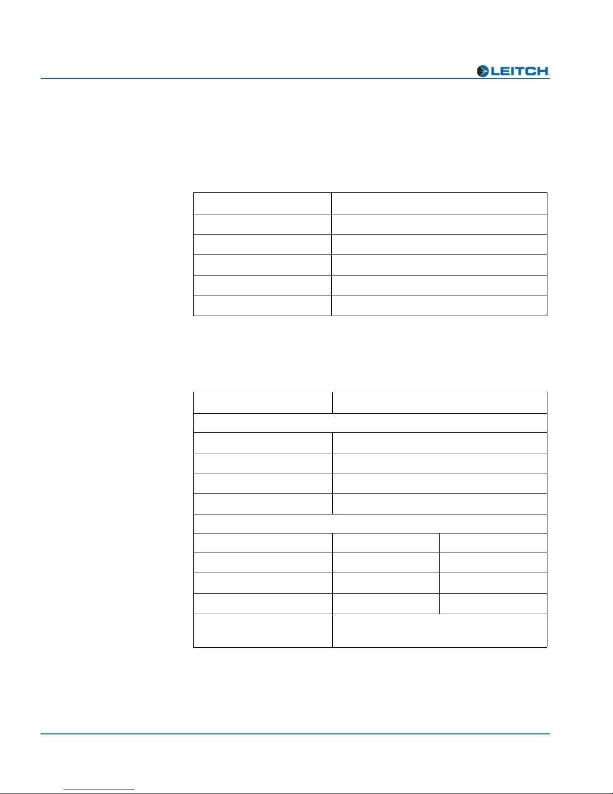
Table P-1. Revision History of Manual
Edition Date Revision History
A October 2002 Initial release
B December 2005 Revisions of product codes, parameter and
default modifications, alarm corrections,
and manual template updates
ADC-3981 Installation and Operation Manual vii

Preface
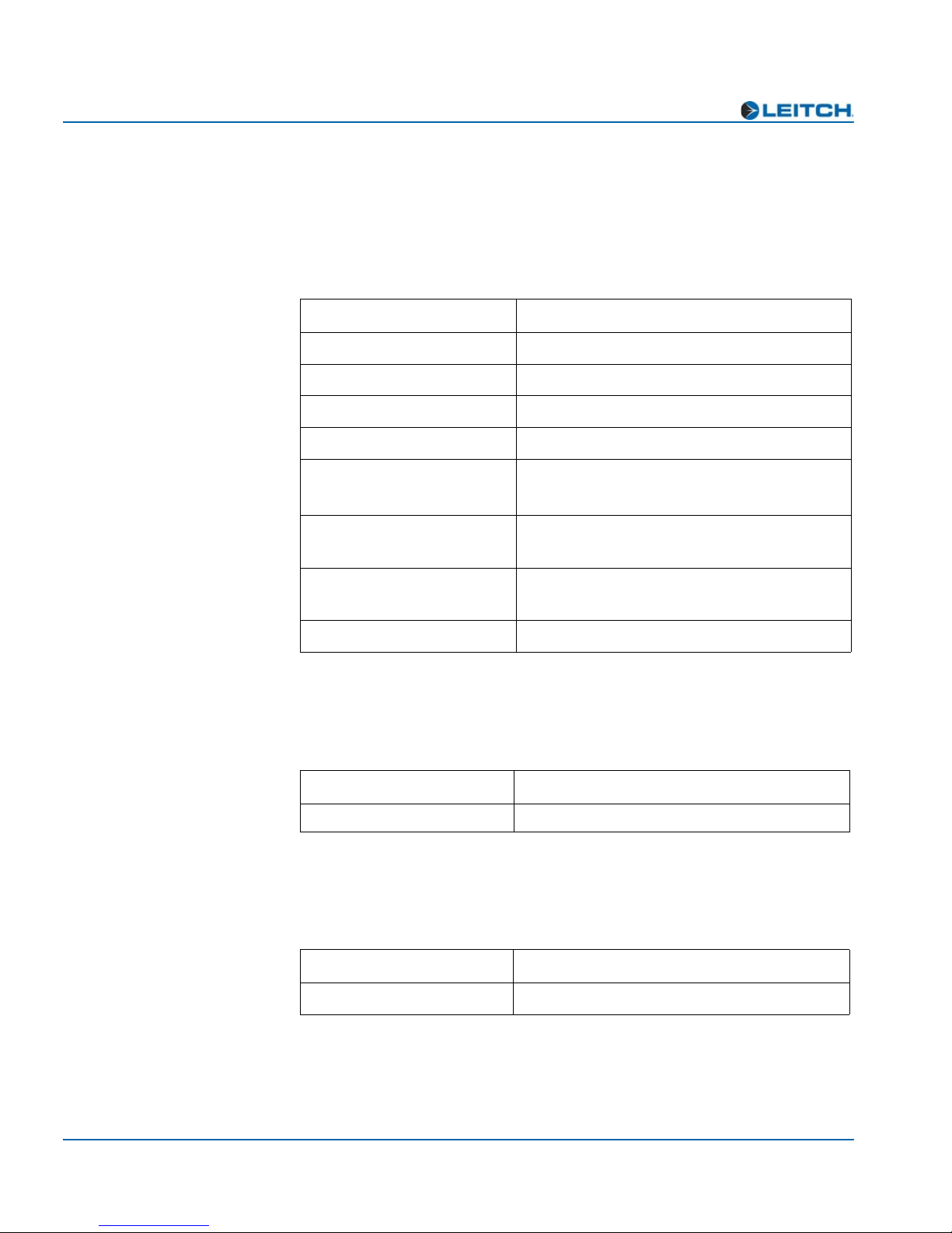
Writing Conventions
This manual adheres to the following writing conventions.
Table P-2. Writing Conventions
Term or Convention Description
Bold Indicates dialog box, property sheet, field,
Italics Indicates email addresses, names of books
CAPS Indicates a specific key on the keyboard,
button, check box, list box, combo box,
menu, submenu, window, list, and
selection names
and publications, and first instances of new
terms and specialized words that need
emphasis
such as ENTER, TAB, CTRL, ALT,
DELETE
Code
> Indicates the direction of navigation
hyperlink Indicates a jump to another location within
Internet address
Note
Indicates variables or command-line
entries, such as a DOS entry or something
you type into a field.
through a hierarchy of menus and
windows.
the electronic document or elsewhere
Indicates a jump to a Web site or URL
Indicates important information that helps
to avoid and troubleshoot problems
viii ADC-3981 Installation and Operation Manual

Obtaining Leitch Documents
Installation, navigation, configuration, and setup information is now
included in the NEO FR-3901, FR-3903, and FR-3923 Mounting
Frames Installation and Operation Manual. If your current NEO frame
manual is Edition A, B, C, or D, you will need to download an updated
version from the Leitch Web site to access this information.
Leitch documents can be viewed or downloaded from the Leitch Web
site at www.leitch.com
Alternatively, contact your Leitch customer service representative to
request a document.
Unpacking the Module
Before you install and configure NEO modules, follow these steps:
1. Check the equipment for any visible damage that may have
occurred during transit.
Preface
(go to Support>Documentation).
2. Confirm that you have received all items listed on the packing list.
3. Remove the anti-static shipping pouch, if present, and all other
packaging material.
4. Retain the original packaging materials for possible reuse.
5. Contact your Leitch sales representative if parts are missing or
damaged.
Keep at least one set of original packaging in the event that a product
needs to be returned for service. If the original package is not available,
you can purchase replacement packaging from Leitch Technology.
Otherwise, you can supply your own packaging as long as it meets the
following criteria:
• The packaging must be able to withstand the product’s weight.
• The product must be held rigid within the packaging.
• There must be at least two inches (five centimeters) of space
between the product and the container.
• The corners of the product must be protected.
If the product is still within the warranty period, Leitch Technology will
return it to you by prepaid shipment after servicing.
ADC-3981 Installation and Operation Manual ix

Preface
Safety Standards and Compliances
See the NEO Safety Instructions and Standards Manual to find the
safety standards and compliances for this NEO series product. A safety
manual is shipped with every FR-3901, FR-3903, and FR-3923
Mounting Frames Installation and Operation Manual and can be
downloaded from the Leitch Web site at www.leitch.com
contact your Leitch customer service representative for a copy of this
safety manual.
Safety Terms and Symbols
This manual uses the following safety terms and symbols. See your
NEO Safety Instructions and Precautions Guide for more information.
Table P-3. Safety Terms and Symbols Used in Manual
. Alternatively,
WARNING:
Statements identifying conditions or practices that can result in
personal injury or loss of life: High voltage is present. Uninsulated
dangerous voltage within the product’s enclosure may be sufficient
to constitute a risk of electric shock to persons.
CAUTION:
Statements identifying conditions or practices that can result in
damage to the equipment or other property: Important operating
and maintenance (servicing) instructions in the literature
accompanying the product.
x ADC-3981 Installation and Operation Manual

Preface
Restriction on Hazardous Substances (RoHS)
Directive
Directive 2002/95/EC—commonly known as the European Union (EU)
Restriction on Hazardous Substances (RoHS)—sets limits on the use of
certain substances found in electrical and electronic equipment. The
intent of this legislation is to reduce the amount of hazardous chemicals
that may leach out of landfill sites or otherwise contaminate the
environment during end-of-life recycling. The Directive takes effect on
July 1, 2006, and it refers to the following hazardous substances:
• Lead (Pb)
• Mercury (Hg)
• Cadmium (Cd)
• Hexavalent Chromium (Cr-V1)
• Polybrominated Biphenyls (PBB)
• Polybrominated Diphenyl Ethers (PBDE)
In accordance with this EU Directive, all Leitch Technology products
sold in the European Union will be fully RoHS-compliant and
“lead-free.” (See the Leitch Web site, www.leitch.com
information on dates and deadlines for compliance.) Spare parts
supplied for the repair and upgrade of equipment sold before
July 1, 2006 are exempt from the legislation. Leitch equipment that
complies with the EU directive will be marked with a RoHS-compliant
symbol, as shown in Figure 1.
Figure 1. RoHS Compliance Symbol
, for more
ADC-3981 Installation and Operation Manual xi

Preface
Waste from Electrical and Electronic
Equipment (WEEE) Directive
The European Union (EU) Directive 2002/96/EC on Waste from
Electrical and Electronic Equipment (WEEE) deals with the collection,
treatment, recovery, and recycling of electrical and electronic waste
products. The objective of the WEEE Directive is to assign the
responsibility for the disposal of associated hazardous waste to either
the producers or users of these products. Effective August 13, 2005,
producers or users will be required to recycle electrical and electronic
equipment at the end of its useful life, and must not dispose of the
equipment in landfills or by using other unapproved methods. (Some
EU member states may have different deadlines.)
In accordance with this EU Directive, Leitch Technology International,
Inc. and other companies selling electric or electronic devices in the
EU will affix labels indicating that such products must be properly
recycled. (See the Leitch Web site, www.leitch.com
information on dates and deadlines for compliance.) Contact your local
Leitch sales representative for information on returning these products
for recycling. Leitch equipment that complies with the EU directive will
be marked with a WEEE-compliant symbol, as shown in Figure 2.
, for more
Figure 2. WEEE Compliance Symbol
xii ADC-3981 Installation and Operation Manual

Overview
Chapter 1: Introduction
Chapter 1
Introduction
The ADC-3981 Analog-to-Digital Converter are designed for use in
NEO™ 1RU and 3RU rack-mounted frames.
This chapter covers the following topics:
• “Product Description” on page 2
• “Front and Back Modules” on page 3
• “Signal Flow” on page 6
Note
Installation, navigation,
configuration, and setup
information for NEO modules is
now included in the NEO
FR-3901, FR-3903, and
FR-3923 Mounting Frames
Installation and Operation
Manual. If your current NEO
frame manual is Edition A, B,
C, or D, you will need to
download an updated version
from the Leitch Web site
(www.leitch.com
information.
) to access this
See the FR-3901, FR-3903, and FR-3923 Installation and Operation
Manual for information about NEO frames. The frame manual includes
information about these items:
• General information about module unpacking, installation,
removal, navigation, configuration, and setup
• Card-edge screen savers
• State recovery parameters
•Fan modules
• Resource modules
• Alarm interconnect modules
• Power supplies
• Servicing instructions
ADC-3981 Installation and Operation Manual 1

Chapter 1: Introduction
Product Description
The ADC-3981 consists of two independent audio processing units,
capable of handling two pairs (four channels) of analog audio inputs,
and two pairs of digital audio outputs. This module has full audio
processing capabilities, including gain, channel swap, invert, and delay
control. The ADC-3981 also has four independent tone generators.
Main Features
These are the main features of the ADC-3981 module:
• Two independent analog-to-digital conversion channels
• 32/44.1/48/96 kHz capability
• Selectable 16-, 20-, and 24-bit analog-to-digital conversion
• Internal audio processing amplifier
• Multiple tone generators (750 Hz, 1.5 kHz, 3 kHz, and 6 kHz)
• Four balanced analog audio inputs
• Peak/Silence/Tone indication
• Selectable delay for each channel
• Two balanced and two unbalanced AES audio outputs
• External video and DARS reference input
• Capability for control via card-edge, local control panels, remote
control panels, and GUI applications (3901RES-E resource module
is required for Ethernet use)
2 ADC-3981 Installation and Operation Manual
Front and Back Modules
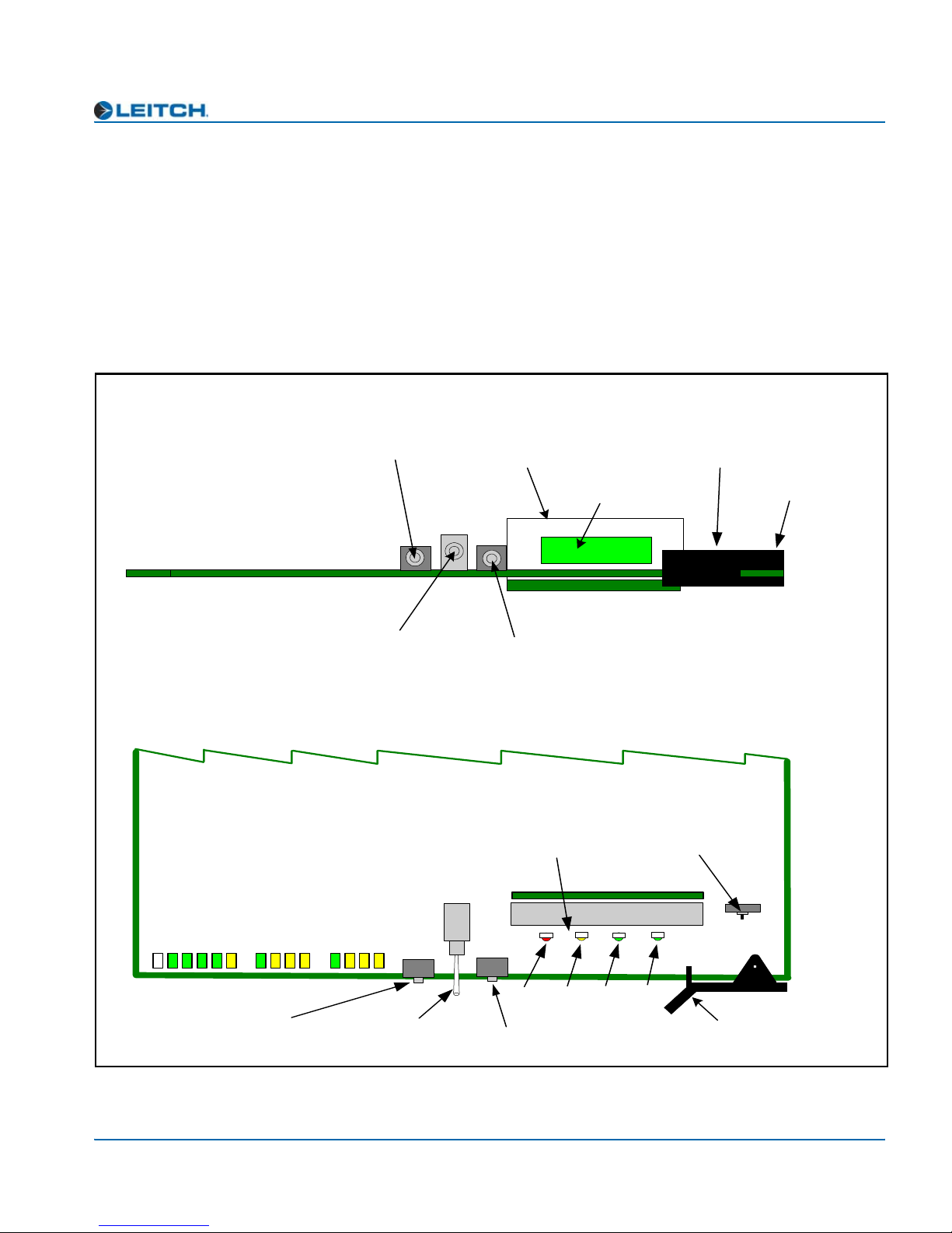
Front Module
NEO front modules are designated by the suffix “-FM.” For example,
the front module of the ADC-3981 is the “ADC-3981-FM.” Figure 1-1
illustrates the position of the LEDs and card-edge controls on the
ADC-3981-FM front module.
Front view
Chapter 1: Introduction
Escape button
Nav+/Nav- switch
(up/down)
64 X 16 VFD
submodule
Top view
Module indicators
Remote/Local switch
(hidden behind extractor)
Visible display area
Enter button
Card extractor
Remote/Local
switch
AES1 Present
Ch1 Peak
Ch1 Mute
Sync/Delay
Genlock Lock
Genlock Present
Genlock Standard
DARS Present
DARS Ref Error
Ch1 Tone
LEDs
Escape button
Figure 1-1. ADC-3981-FM Front Module
ADC-3981 Installation and Operation Manual 3
Ch2 Mute
Ch2 Tone
AES2 Present
Ch2 Peak
Nav +
Nav -
Nav+/Nav- switch
(up/down)
Enter
Esc
MAJOR
ALARM
Enter button
Major
Alarm
MINOR
ALARM
Minor
Alarm
Power
POWER
REM LOC
Module
Status
MODULE
STATUS
Extractor handle
SW1
Chapter 1: Introduction
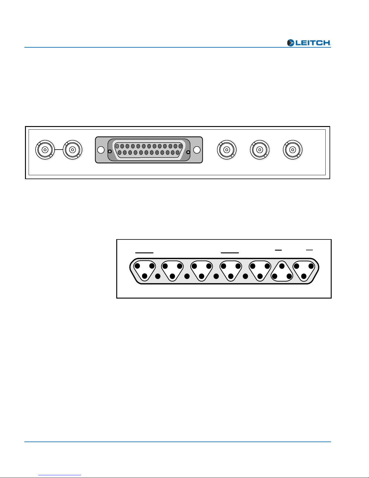
Back Module
In the NEO frame, back modules are placed directly behind the front
modules. Back modules are designated by the suffix “-BM”. For
example, the back module of the ADC-3981 is the “ADC-3981-BM.”
Figure 1-2 shows the ADC-3981-BM back module.
UNBALANCED AES OUT
GENLOCK
INPUT/LOOP
ANALOG AUDIO IN DARS BALANCED AES INPUT
Figure 1-2. ADC-3981-BM Back Module
Back Module Pinouts
Figure 1-3 shows the pinouts for the Analog Audio In, DARS In, and
Balanced AES Out connectors on the ADC-3981-BM back module.
13
25
AG
-
+
Channel
2B
Figure 1-3. ADC-3981-BM Back Module Balanced Pinouts
Balanced analog audio in
AG
+
AG
Channel
2A
AG
-
-
+
AG AG
Channel
1B
IN DARS CHANNEL 1 CHANNEL 2
Balanced
AES out
-
G
+
Channel 2
-
Channel 1
AG
-
+
Channel
1A
DARS in
-
G
AG
+
ADC-3981
G
1
+
14
4 ADC-3981 Installation and Operation Manual

Plug-In Adapter
Chapter 1: Introduction
The ADC-3981-BM back module is shipped with a detachable plug-in
adapter (AIB-25-MF) for connecting twisted-pair audio cables directly
to the back module. Figure 1-4 identifies the screw terminals for the
AIB-25-MF plug-in adapter.
Analog audio input (1st two rows)
G
G
+ – G
G
+ – G
G
Ch 2A
+ –
Ch 1A
G
balanced
G
– +
Analog
grounds
Digital
grounds
Ch 2B
G
G
+ –
Ch 1B
+ –
G
AES 1 AES 2 DARS
balanced balanced
Digital audio output and DARS input (3rd row)
G
G
+ –
Figure 1-4. Screw Terminals for the AIB-25-MF Plug-in Adapter
ADC-3981 Installation and Operation Manual 5
Chapter 1: Introduction
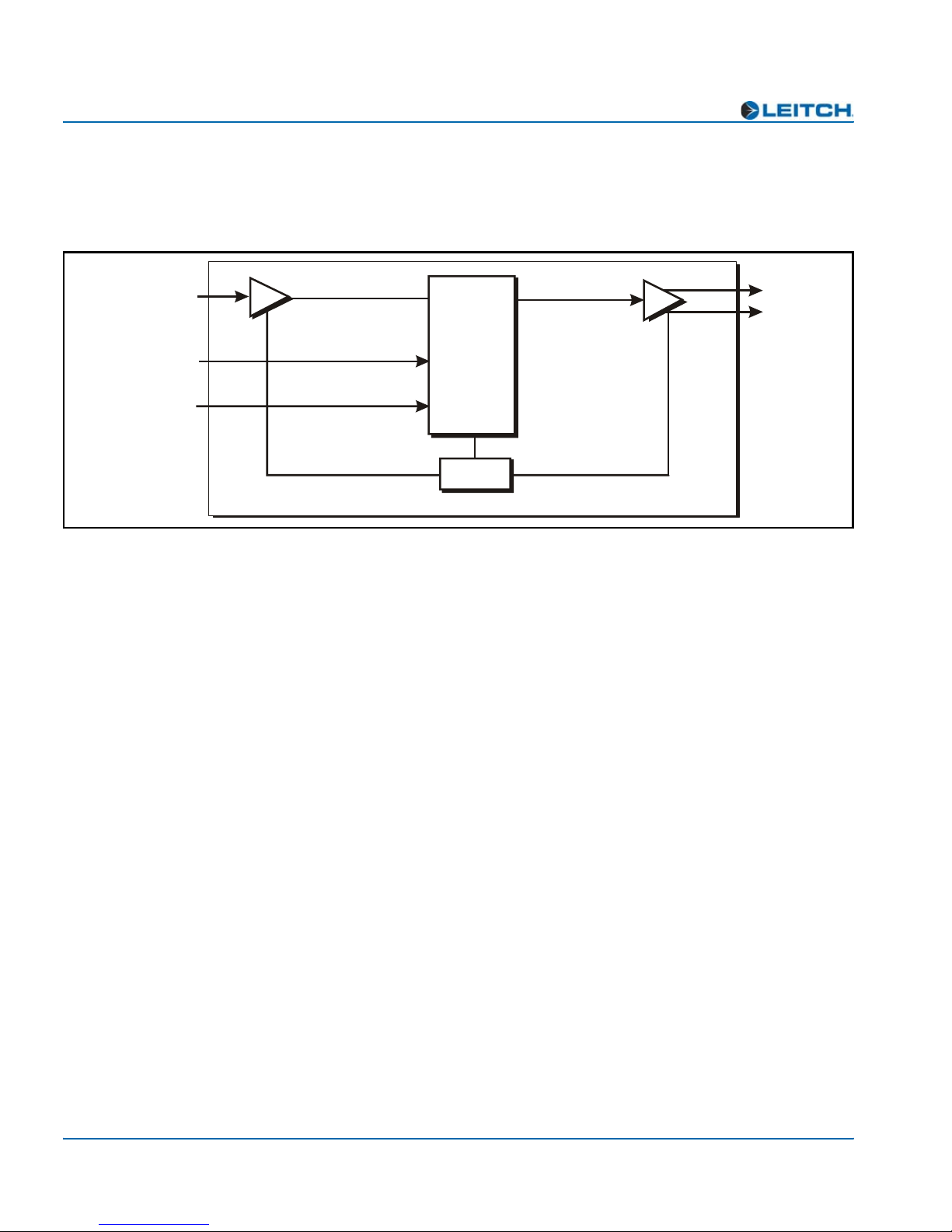
Signal Flow
Figure 1-5 illustrates the signal flow of the ADC-3981.
4 analog audio or
2x2 analog audio
Composite Analog
Reference
(NTSC or PAL)
DARS
A-D
CPU
Figure 1-5. ADC-3981 Functional Block Diagram
2 AES (75 )
2 AES (110 )
Ω
Ω
6 ADC-3981 Installation and Operation Manual
Overview
Caution
Before installation, please read
the NEO Safety Instructions and
Precautions Manual. This
document contains important
information about the safe
installation and operation of
NEO products.
Chapter 2
Installation and Removal
Installation, navigation, configuration, and setup information is now
included in the NEO FR-3901, FR-3903, and FR-3923 Mounting
Frames Installation and Operation Manual. If your current NEO frame
manual is Edition A, B, C, or D, you will need to download an updated
version from the Leitch Web site (www.leitch.com
information.
In this chapter, you can find information on the following topics:
• “Packing List” on page 8
) to access this
• “Installing ADC-3981 Modules” on page 8
• “Removing ADC-3981 Modules” on page 8
• “Setting Jumpers” on page 9
• “Upgrading ADC-3981 Firmware” on page 11
• “Correcting a Failed Upgrading Procedure” on page 15
ADC-3981 Installation and Operation Manual 7

Chapter 2: Installation and Removal
Packing List
The ADC-3981 package includes these items:
• One ADC-3981-FM front module
• One ADC-3981-BM back module
• One AIB-25-MF sub-module
•One ADC-3981 Analog-to-Digital Converter Installation and
Operation Manual per manual
Installing ADC-3981 Modules
For general information about installing NEO modules, see your NEO
FR-3901, FR-3903, and FR-3923 Mounting Frames Installation and
Operation Manual. See page 9 for more information about setting
jumpers on the ADC-3981 manual.
Removing ADC-3981 Modules
This module requires no specialized removal procedures. For general
information about removing NEO modules, see your NEO FR-3901,
FR-3903, and FR-3923 Mounting Frames Installation and Operation
Manual.
8 ADC-3981 Installation and Operation Manual

Setting Jumpers
The ADC-3981 has the following jumpers:
Chapter 2: Installation and Removal
• Four 600
Ω/Hi-Z analog impedance input jumpers
• One set of balanced/unbalanced DARS input jumpers
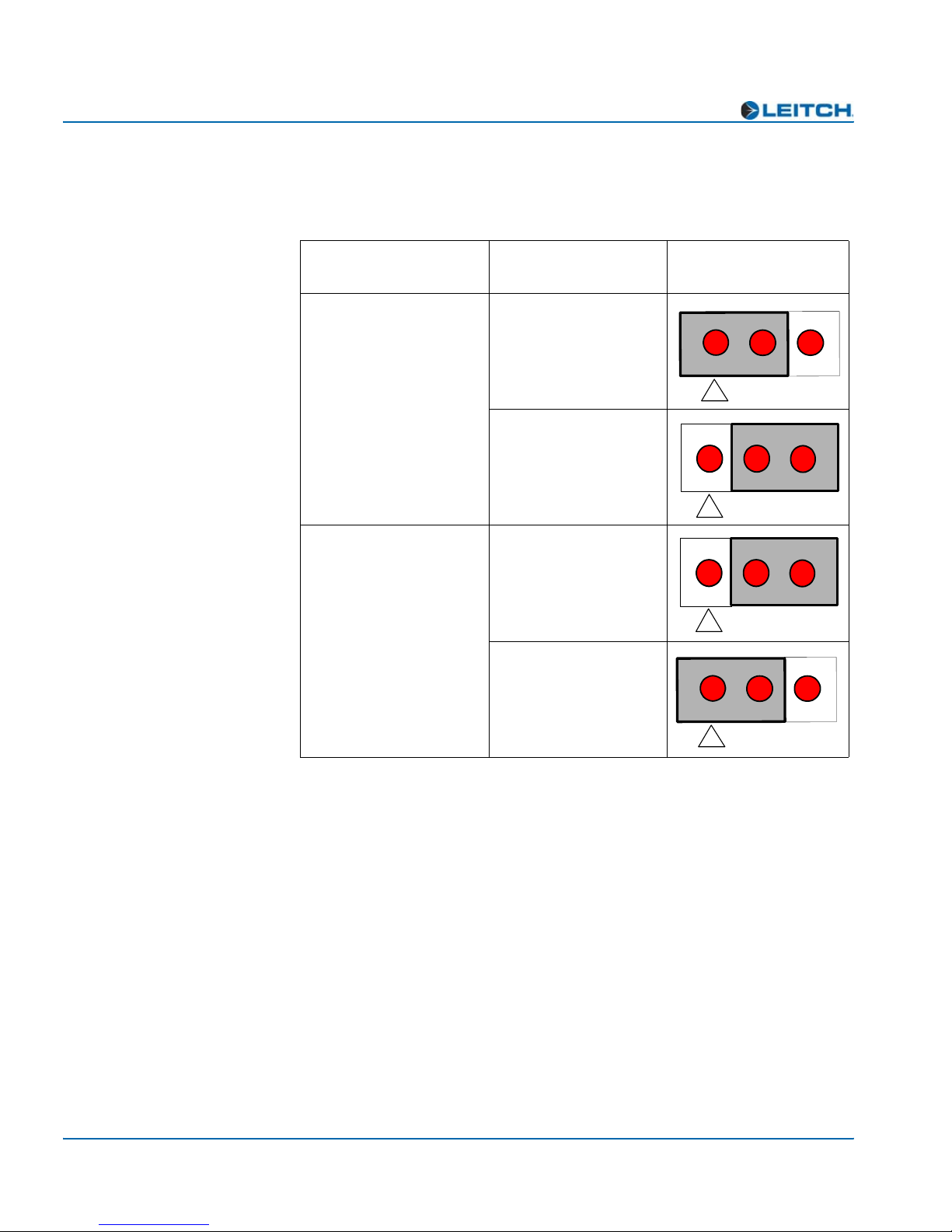
See Figure 2-1 for the location of these jumpers, and the table on
page 10 for the configuration of the jumpers. Each jumper set consists
of three upright pins. In each set, Pin 1 is marked with a small white
triangle.
Jumpers J28 and J29
(balanced/unbalanced
DARS)
Jumper J30
(600
Ω
/Hi-Z Ch 1A)
Jumper J31
Ω
/Hi-Z Ch 1B)
(600
Jumper J32
(600
Ω
/Hi-Z Ch 2A)
Jumper J33
(600
Ω
/Hi-Z Ch 2B)
Figure 2-1. ADC-3981 DARS and Impedance Jumpers
ADC-3981 Installation and Operation Manual 9
Chapter 2: Installation and Removal
Table 2-1 identifies the four valid jumper configurations for the
ADC-3981.
Table 2-1. Jumper Configuration
Jumper Name
Jumpers J28 and J29
(balanced and
unbalanced DARS
Jumpers J30-J33
(600Ω /Hi-Z)
Jumper Pair
Setting
Balanced
Unbalanced
(default)
600Ω
Hi-Z
(default)
Visual
Configuration
2
1
1
1
2
2
2
1
3
3
3
3
10 ADC-3981 Installation and Operation Manual

Chapter 2: Installation and Removal
Upgrading ADC-3981 Firmware
Firmware upgrading is a routine procedure that you must perform to
install newer versions of software on the ADC-3981 module. Pilot,
Co-Pilot, or Navigator software applications are required for this
procedure. You can use either the Discovery or the drag-and-drop
method. When performing the upgrading procedure, check the
appropriate readme file to confirm which files are needed. Use care to
ensure that you upload the correct files to the intended module.
If for some reason the upgrade fails, the module may not respond to
controls and will appear to be non-functional. In that event, follow the
procedures described in “Correcting a Failed Upgrading Procedure” on
page 15.
Upgrading the Firmware (Discovery Method)
Follow these steps to upgrade the firmware using the Discovery
method:
1. Download the most recent appropriate upgrade package from the
Leitch Web site or from your CD-ROM, and then unzip the upgrade
package.
2. If the affected module has not been discovered, perform the
Discovery operation, as described in your CCS software
application manual or online help.
3. Double-click the device icon.
The Configuration... window opens. On the Software Upgrade
tab, the /slotx/boot (where x is the slot number) directory appears
in the Select the device directory to transfer to: field.
4. Click Add, and in the Add Upgrade Files box, browse and select
the boot folder in the module’s upgrade; click OK.
The Add Upgrade Files box appears.
5. Select the file and then click OK.
6. Click Perform Transfer and then click Yes.
ADC-3981 Installation and Operation Manual 11
This may take several minutes.
7. Wait for the message File transfer to device succeeded in the
status bar.

Chapter 2: Installation and Removal
If an fl0 folder is included in the .zip file, the files within that folder
must now be uploaded as shown below. (In some cases, the readme file
may indicate other separate files must be uploaded instead.)
Follow these steps to upload the remaining files:
1. On the Software Upgrade tab, select the /slotx/fl0 (where x is the
2. Click Add, and in the Add Upgrade Files box, browse and select
3. Click OK.
4. Select the files shown in the Add Upgrade Files box, and then
Caution
You must delete unwanted files
in the Add upgrade files for
transfer to device: field before
transferring the files. Otherwise,
the upgrading procedure will
fail.
5. Select and delete unwanted files (for example: vxWorks.lzs) in the
6. Click Perform Transfer and then click Yes.
7. Wait for the message File transfer to device succeeded.
slot number) directory in the Select the device directory to
transfer to: field.
the fl0 folder in the module’s upgrade package.
click OK.
Add upgrade files for transfer to device: field by clicking
Remove.
This may take a moment.
8. Click Reboot Device and then click Yes.
9. Wait 30 seconds, and then close the Configuration... box.
The module name appears at the card edge.
12 ADC-3981 Installation and Operation Manual
Chapter 2: Installation and Removal
Upgrading the Firmware (Drag-and-Drop Method)
Follow these steps to upgrade the firmware using the drag-and-drop
method:
1. Download the appropriate most recent upgrade package from the
Leitch Web site or from your CD-ROM, and then unzip the upgrade
package.
2. If the affected module has not been discovered by your CCS
software application, enter the Build mode, and then drag or copy
and paste the module’s device icon from the catalog folder into the
Network or Discovery folder.
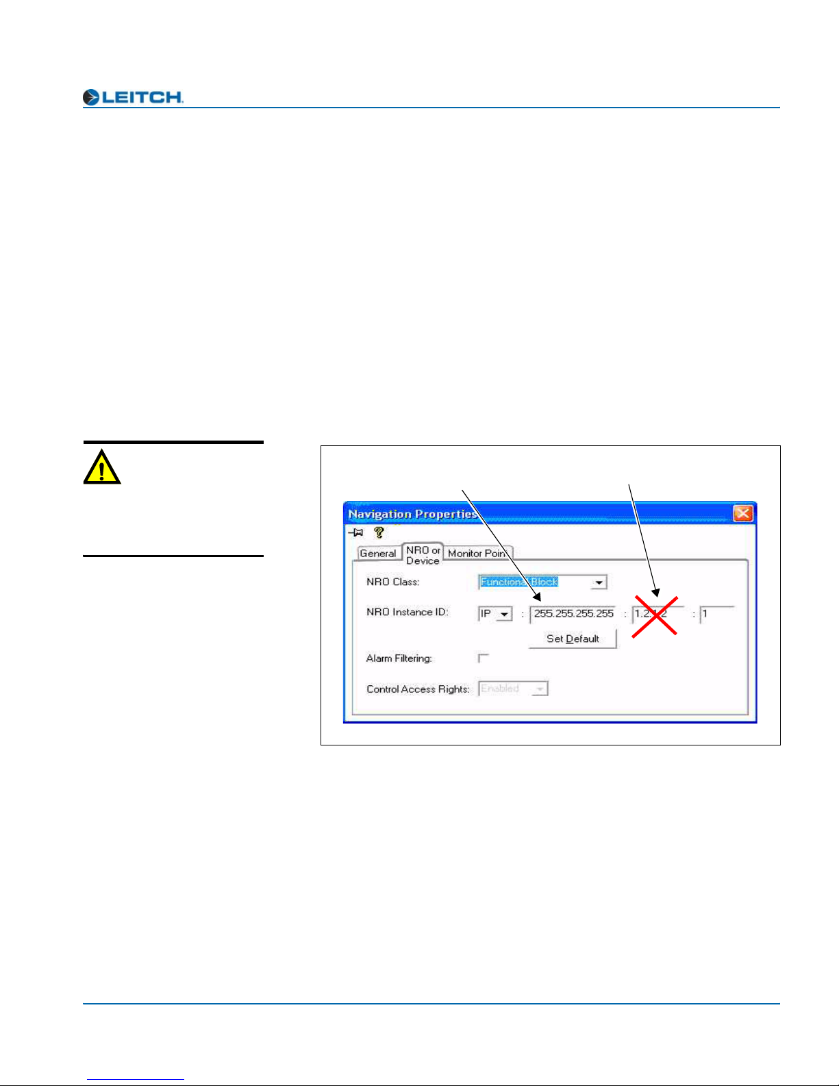
3. Right-click the device icon and then select Properties.
4. On the NRO or Device tab of the Navigation Properties box, enter
the IP address of the frame that holds the module. (See Figure 2-2.)
Caution
Do not make changes in the
third field (located above and to
the right of the Set Default
button.)
Enter frame IP number here
Do not make changes in
this field
Figure 2-2. Navigation Properties Box
5. In the last field, enter the slot number of the module, and then close
the window.
6. Double-click the device icon.
ADC-3981 Installation and Operation Manual 13
The Configuration... window opens. On the Software Upgrade
tab, the /slotx/boot (where x is the slot number) directory appears
in the Select the device directory to transfer to: field.
7. Click Add, and in the Add Upgrade Files box, browse and select
the boot folder in the module’s upgrade.

Chapter 2: Installation and Removal
8. Click OK.
9. Select the file and then click OK.
10. Click Perform Transfer and then click Ye s .
11. Wait for the message File transfer to device succeeded in the
If an fl0 folder is included in the .zip file, the files within that folder
must now be uploaded as shown below. (In some cases, the readme file
may indicate other separate files must be uploaded instead.)
Follow these steps to upload the remaining files:
1. On the Software Upgrade tab, select the /slotx/fl0 (where x is the
The Add Upgrade Files box appears.
This may take several minutes.
status bar.
slot number) directory in the Select the device directory to
transfer to: field.
Caution
You must delete unwanted files
in the Add upgrade files for
transfer to device: field before
transferring the files. Otherwise,
the upgrading procedure will
fail.
2. Click Add, and in the Add Upgrade Files box, browse and select
the fl0 folder in the module’s upgrade package.
3. Click OK.
4. Select the files shown in the Add Upgrade Files box, and then
click OK.
5. Select and delete unwanted files (for example: vxWorks.lzs) in the
Add upgrade files for transfer to device: field by clicking
Remove.
6. Click Perform Transfer and then click Yes.
7. Wait for the message File transfer to device succeeded.
This may take a moment.
8. Click Reboot Device and then click Yes.
9. Wait 30 seconds and then close the Configuration... box.
The module name appears at the card edge.
14 ADC-3981 Installation and Operation Manual

Chapter 2: Installation and Removal
Correcting a Failed Upgrading Procedure
Firmware upgrades may fail in the event of network interruptions,
power failures, or if too much data is uploaded to the NEO module.
Often, uploads of too much data can occur for one of the following
reasons:
• The boot file (typically vxWorks.lzs) was accidentally uploaded
during the fl0 procedure, instead of the boot procedure.
• Files were sent to the wrong NEO module.
• The particular hardware version of the module requires only some
(but not all) of the available fl0 files.
• The upgrade .zip file was mistakenly sent to the module.
All of these problems can be corrected by re-installing the firmware
while in a fail-safe mode, as described in the following pages. When
you are performing this procedure, check the appropriate readme file to
confirm which files are needed. Use care to ensure that you upload the
correct files to the intended module.
Setting the Module to Fail-Safe Loader Mode
Follow these steps to set a NEO module to the fail-safe loader mode:
1. Remove the affected module from the NEO frame.
2. Press the Nav switch down while simultaneously pressing both the
Escape and Enter buttons.
3. While still pressing the buttons and the navigation switch, reinsert
the module into the frame and hold for approximately three seconds
until the display on the module reads Offline-H (or Offline-L)
Upload Required.
Upgrading the Firmware in Fail-Safe Mode
Follow these steps to upgrade the firmware in the fail-safe mode:
Note
To successfully upgrade the
firmware, you must follow these
steps in the exact sequence
described.
1. Download the most recent appropriate upgrade package from the
Leitch Web site or from your CD-ROM, and then unzip the upgrade
package.
ADC-3981 Installation and Operation Manual 15

Chapter 2: Installation and Removal
2. If the affected module has not been discovered by your CCS
3. Right-click the device icon and then select Properties.
4. On the NRO or Device tab of the Navigation Properties box, enter
software application, enter the Build mode, and then drag or copy
and paste the module’s device icon from the catalog folder into the
Network or Discovery folder.
the IP address of the frame that holds the module. (See Figure 2-3.)
Caution
Do not make changes in the
third field (located above and to
the right of the Set Default
button.)
Enter frame IP number here
Do not make changes in
this field
Figure 2-3. Navigation Properties Box
5. In the last field, enter the slot number of the module, and then close
the window.
6. Double-click the device icon.
The Configuration... box opens. On the Software Upgrade tab,
the /slotx/boot (where x is the slot number) directory appears in the
Select the device directory to transfer to: field.
7. Click Add, and in the Add Upgrade Files box, browse and select
8. Click OK.
9. Select the file and then click OK.
10. Click Perform Transfer and then click Ye s .
11. Wait for the message File transfer to device succeeded in the
16 ADC-3981 Installation and Operation Manual
the boot folder in the module’s upgrade.
This may take several minutes.
status bar.

Rebooting the Module
Follow these steps to reboot the affected NEO module:
Note
Some NEO modules will reboot
automatically. In these cases,
the Reboot button will be
grayed out. During this time, the
module’s card-edge display will
show the word Rebooting
before the name of the module
appears. These modules do not
require the fl0 file.
1. Click Reboot Device, and then click Ye s.
After the module has rebooted, a message box advises you to wait
until the device has rebooted.
2. Wait 30 seconds.
3. On the Software Upgrade tab, select the /slotx/fl0 (where x is the
slot number) directory in the Select the device directory to
transfer to: field.
4. Click Add, and then browse and select the fl0 folder in the
module’s upgrade package.
5. Click OK.
6. Select the files shown in the Add Upgrade Files box, and then
click OK.
Chapter 2: Installation and Removal
Caution
You must delete unwanted files
in the Add upgrade files for
transfer to device: field before
transferring the files. Otherwise,
the upgrading procedure will
fail.
7. Select and delete unwanted files (for example: vxWorks.lzs) in the
Add upgrade files for transfer to device: field by clicking
Remove.
8. Click Perform Transfer and then click Yes.
9. Wait for the message File transfer to device succeeded.
This may take a moment.
10. Click Reboot Device and then click Yes.
11. Wait 30 seconds, and then close the Configuration... box.
The module name appears at the card edge.
ADC-3981 Installation and Operation Manual 17

Chapter 2: Installation and Removal
18 ADC-3981 Installation and Operation Manual

Overview
Chapter 3
Operation
Installation, navigation, configuration, and setup information is now
included in the NEO FR-3901, FR-3903, and FR-3923 Mounting
Frames Installation and Operation Manual. If your current NEO frame
manual is Edition A, B, C, or D, you will need to download an updated
version from the Leitch Web site (www.leitch.com
information.
) to access this
This chapter describes how to operate the ADC-3981 module using
card-edge controls.
The following topics are found in this chapter:
• “Operation Notes” on page 20
• “Cross-Functional Parameter Changes” on page 21
• “Navigating the Operator and All Lists” on page 22
• “Operator and All List Parameters” on page 23
• “Setup Parameters” on page 26
• “Alarms” on page 27
• “State Recovery Parameter Availability” on page 28
• “LEDs and Module Indicators” on page 29
ADC-3981 Installation and Operation Manual 19

Chapter 3: Operation
Operation Notes
When using the ADC-3981 module, observe the following operation
Caution
notes:
If you do not observe these
“Operation Notes”, you may
accidentally change your
parameter settings.
• If you change parameters within 16 seconds after the ADC-3981
banner first appears on the VFD, your changes will not be saved.
Parameter changes that you make after this 16-second delay will be
saved and restored if the module loses power and must be restarted.
• Although the effect of a parameter change may appear to be
immediate, the module requires 20 seconds to save the latest
change. If another change is made during these 20 seconds, the first
parameter change and the second parameter change will not be
saved until 20 seconds after the second parameter change. There is
no limit to the number of changes that can be made within 20
seconds of each other. However, none of these changes will be
saved until 20 seconds after the last parameter change.
• When the FctryRcl (factory recall) parameter is set to Ye s, the
module takes several seconds to reset all of the parameters. (See
the “Operator and All List Parameters” on page 23 or the “Tree
View Parameters” on page 39 to view the factory recall default
settings.) Setup parameters are not affected by the factory recall
mode.
• Changes in some parameters will cause additional changes in other
parameters, or lock them out entirely. See page 21 for more
information on these cross-functional parameter changes.
20 ADC-3981 Installation and Operation Manual

Cross-Functional Parameter Changes
When you select values in certain specific parameters, you force
changes to occur in other parameters. Table 3-1 describes the
cross-functional parameter changes for the ADC-3981.
Table 3-1. Cross-Functional Parameter Changes
Condition Forced Setting
Chapter 3: Operation
SampleRate=set to a new option
• Delay_1A initialized to 0
• Delay_1B initialized to 0
• Delay_2A initialized to 0
• Delay_2B initialized to 0
ADC-3981 Installation and Operation Manual 21

Chapter 3: Operation
Navigating the Operator and All Lists
To navigate, and then view or change a parameter from the Operator
and All Lists, follow these steps:
1. Open the front panel of the NEO frame.
2. Press any card-edge control to turn on the VFD screen.
The message ADC-3981 appears. If a previous user has left the
display at a different parameter name, repeatedly press the Escape
button until the message ADC-3981 appears.
3. Push the Enter button.
Note
After several seconds of
inactivity, a scrolling message
will appear, describing the
purpose of the currently selected
parameter.
The name of the first parameter option in the list appears.
4. Push the Enter button again to access the options for the parameter
displayed on the VFD screen.
OR
Press the Nav+/Nav- switch down repeatedly to view other
parameters, and then press Enter to access an item’s parameter
options.
5. Press the Nav+/Nav- switch up or down to scroll through the
different selectable parameter options, and then press Enter to
select the value you want.
OR
Press the Nav+/Nav- switch up or down to adjust the numeric
parameter value, and then press Enter.
6. Close the front panel of the frame to ensure the cooling system
continues to operate properly.
22 ADC-3981 Installation and Operation Manual
Operator and All List Parameters
This complete list of parameter settings is arranged so that the settings
Note
You can reset the default values
for all of the parameters
automatically via the FctryRcl
parameter, found in this table.
most likely requiring changes are placed at the top of the list. Items on
the bottom of the list are the least likely to require changing. Parameters
with the designation [RO] are “read-only.” An asterisk (*) indicates the
default user range or value.
The All List is a long flat list of all the available parameters, arranged
from the most-used to least-used. It is intended for a “Supervisor”
security designation. The Operator List is a condensed version of the
All List, and is intended for an “Operator” security designation. The
following table shows all available parameters. Parameters accessed
only from within the All List are shaded in gray.
See “Navigating the Operator and All Lists” on page 22 for instructions
on navigating this list using card-edge controls.
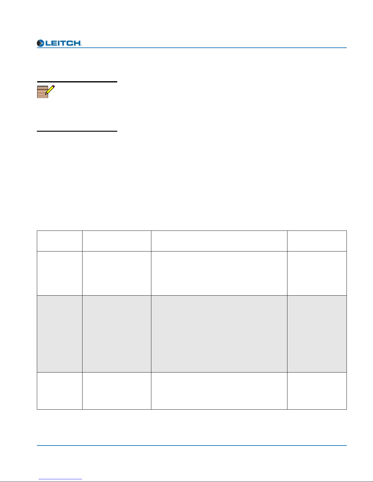
Chapter 3: Operation
Table 3-2. Operator and All List Parameters
Card-Edge
ID
SampleRate Sample Rate Sets the sample rate
Delay_1A,
Delay_1B,
Delay_2A,
Delay_2B
Gain_1A,
Gain_1B,
Gain_2A,
Gain_2B
Parameter Name Function
Delay: In Channel 1A
to
Delay: In Channel 2B
Gain: In Channel 1A
to
Gain: In Channel 2B
Adjusts the delay for input channel 1A to input
channel 2B
Adjusts the gain for input channel 1A to input
channel 2B
User Range
or Options
• 32 kHz
• 44.1 kHz
• 48 kHz*
• 96 kHz
• 0* to 2047.8 ms
@ 32 kHz
• 0* to 1486.0 ms
@ 44.1 kHz
• 0* to 1365.2 ms
@ 48 kHz
• 0* to 682.6 ms
@ 96 kHz
-18.0 to 18.0 dB
(0 dB*)
ADC-3981 Installation and Operation Manual 23

Chapter 3: Operation
Table 3-2. Operator and All List Parameters (Continued)
Card-Edge
ID
Invert1A,
Invert1B,
Invert2A,
Invert2A
Out1ASrc Out 1A Source Selects the source for output channel 1A
DitherMode Output Dither Mode Selects the dithering mode for all outputs
Parameter Name Function
Invert: In Channel 1A
to
Invert: In Channel 2B
Inverts the input channel 1A to input channel
2B
User Range
or Options
•Yes
•No*
• In 1A*
(Out1ASrc)
• In 1B*
(Out1BSrc)
• In 2A*
(Out2ASrc)
• In 2B*
(Out2BSrc)
•Mute
• Tone1
• Tone2
• Tone3
•Tone4
• None*
•On
Out1_Resln Out Channel 1 Resln Selects the dithering resolution for output
channel 1
Out2_Resln Out Channel 2 Resln Selects the dithering resolution for output
channel 2
AudIp1Lvl,
AudIp2Lvl
Tone1Lvl Tone 1 Level Set Adjusts the level of the 750 Hz audio tone
Tone2Lvl Tone 2 Level Set Adjusts the level of the 1500 Hz audio tone
Tone3Lvl Tone 3 Level Set Adjusts the level of the 3000 Hz audio tone
Tone4Lvl Tone 4 Level Set Adjusts the level of the 6000 Hz audio tone
Audio Input 1 Level to
Audio Input 2 Level
Indicates the operational level adjustment for
input channel 1 to input channel 2
generator
generator
generator
generator
• 24 bits
• 20 bits*
• 16 bits
• 24 bits
• 20 bits*
• 16 bits
12.0 to 28.0 dB
(24* dB)
-36.0 to 0.0 dBFS
(-18.0* dBFS)
-36.0 to 0.0 dBFS
(-18.0* dBFS)
-36.0 to 0.0 dBFS
(-18.0* dBFS)
-36.0 to 0.0 dBFS
(-18.0* dBFS)
24 ADC-3981 Installation and Operation Manual
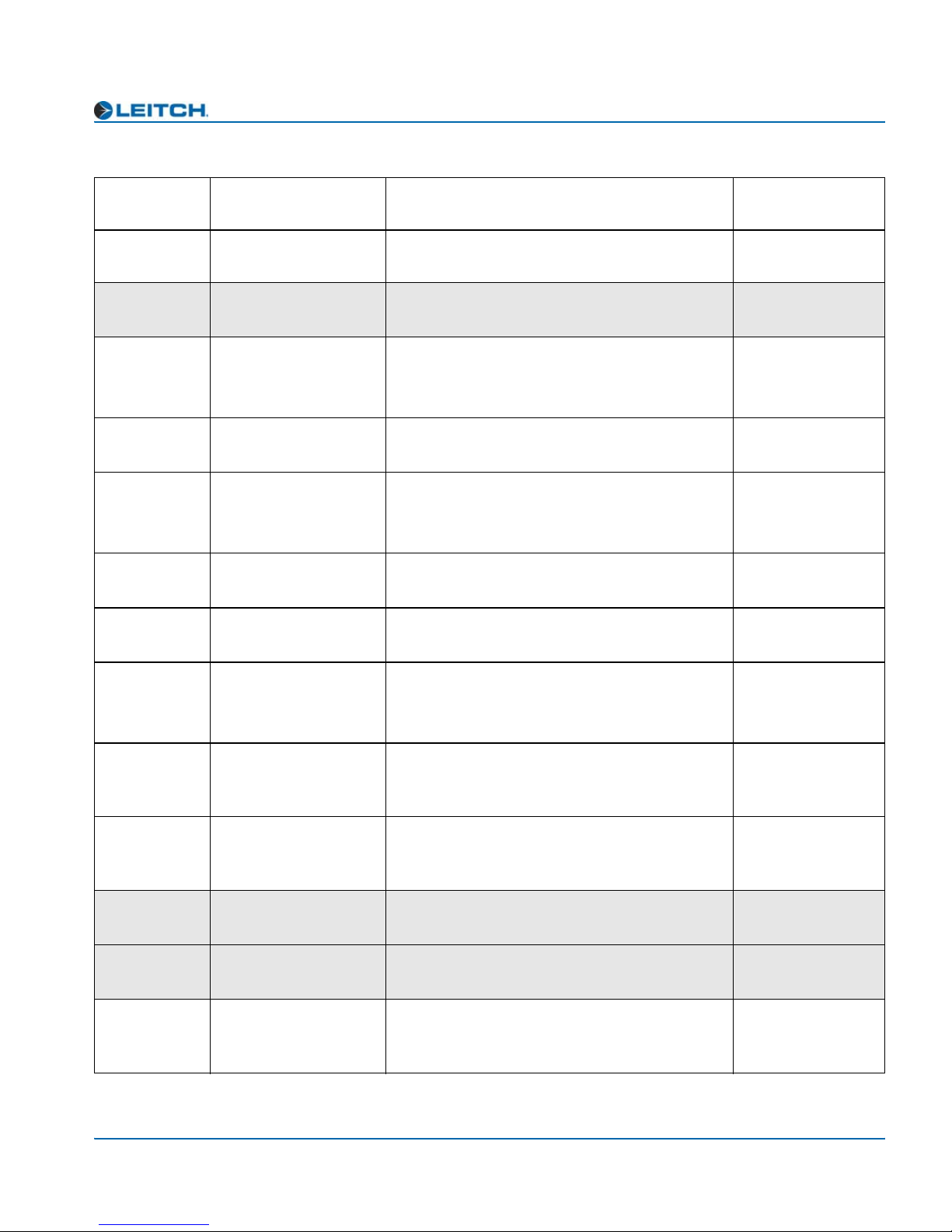
Table 3-2. Operator and All List Parameters (Continued)
Chapter 3: Operation
Card-Edge
ID
FadeRate Fade Rate Controls the fading rate when channels are
LockMode Lock Mode Sets the module working mode
LckSource Lock Source Selects the reference source for the on-board
DARSPrsnt
[RO]
DARSRefErr
[RO]
GlStdFb
[RO]
GlVPrsnt
[RO]
Parameter Name Function
swapped or muted
genlock circuitry
DARS Signal Present Returns the presence of input DARS signal
DARS Reference
Error
Genlock Video
Standard Feedback
Genlock Video
Present
Returns the locking status of DARS input with
respect to external reference video signal
Returns the detected external reference signal
standard
Returns the presence of the video signal from
the external reference source
User Range
or Options
0 s to 10.0 s
(0.010 s*)
• Delay*
• FreeRun
• DnStream
• DARS
• Card GL*
•Yes
•No
• Error
• No Error
• Not Valid
•PAL-B
•NTSC
•Yes
•No
GlLocked
[RO]
Ch1Peak,
Ch2Peak
[RO]
Ch1Mut,
Ch2Mute
[RO]
DnBusEn Down Bus Enable Allows the passing of signals to downstream
Fctry_Rcl Factory Recall Recalls factory default settings
Setup Setup Parameters Sets the parameters for display and usability
Genlock Locked Returns the locked status of the external
reference signal
Out Channel 1 Peak
Out Channel 2 Peak
Out Channel 1 Mute
Out Channel 2 Mute
Indicates that channel 1to channel 2 is above
peak
Indicates that channel 1 to channel 2 is muted
card for concatenated function
(see page 40 for a complete list of Setup
parameters and their factory default settings)
• Not Locked
• Locked
• Not Valid
•Yes
•No
•Yes
•No
•Yes
•No*
•Yes
•No*
Various
ADC-3981 Installation and Operation Manual 25

Chapter 3: Operation
Setup Parameters
You can modify the Setup parameters to configure the card-edge
Note
Setup parameters on a local or
remote control panel may be
different from the card-edge
parameters described here.
controls for your personal needs. The Setup section appears at the end
of all three navigation lists and consists of these items:
•Alarms
• Navigation modes
• Adjustment modes
• Browse modes
• Scroll modes
• Display intensity
• Parameter descriptions
•Name
• FrameIP
•Sync full
• About mode
The structure of the Setup menu is located at the end of Appendix A:
“Tree View Navigation.” See your NEO FR-3901, FR-3903, and
FR-3923 Mounting Frames Installation and Operation Manual for
more information on Setup items, including descriptions and operation
notes.
26 ADC-3981 Installation and Operation Manual

Alarms
ADC-3981 modules provide a default list of four alarms. You can
disable any alarm by modifying the Alarms parameter in the Setup
section.
When you select Alarms, all of the active alarms are visible in the
display, below Config (Configurations). If no alarms are active, only
Config appears.
Alarm Synchronization
Alarm synchronization is available for this module if your NEO frame
contains a 3901RES-E resource module that supports the feature. When
active, alarm synchronization ensures that the alarm configuration
settings of card-edge controls and the CCS control software and control
panels are consistent.
Chapter 3: Operation
If the ADC-3981 module is set for local control, the alarm settings will
appear the same at both the card edge and via CCS, but the settings can
only be changed using the card-edge controls. If the module is set for
remote control, the alarm settings can be changed via both the card edge
and CCS control software and control panels.
Alarm configuration settings undergo DejaView (state recovery)
automatically. This means that when a module is hot-swapped, the
alarm configuration for the new module is updated to the settings of the
module that was previously in that slot. See “State Recovery Parameter
Availability” in this chapter for more information.
Identifying the Cause of an Alarm
To identify the reason for an alarm, select the active alarm, and then
press Enter. A scrolling message appears on the VFD describing the
cause of the fault.
ADC-3981 Installation and Operation Manual 27

Chapter 3: Operation
Enabling or Disabling an Alarm Parameter
To enable or disable an alarm parameter, follow these steps:
1. Select Alarms, then select Config, and then press Enter.
2. Select one of the alarm parameters, and then press Enter.
3. Press Enabled or Disabled.
4. Press Enter to activate the selection.
Restoring Default Settings
To restore the alarms to their default settings, follow these steps:
1. Select Alarms, select Config, and then press Enter.
2. Scroll down the list of alarms, and then select Reset.
3. Press Enter to activate the selection.
The following table lists the default alarms for the ADC-3981 module.
You can enable or disable these settings, but you cannot change the
level of the alarm.
Table 3-3. ADC-3981 Default Alarms
Card-Edge
Alarm ID
DARSPrsnt DARS Present Major Loss of DARS reference
DARSRefErr DARS Reference Error Minor Error in the DARS reference signal
GlVPrsnt Genlock Video Present Major Loss of genlock video reference
GlLocked Genlock Locked Major Loss of locked reference
Name of Alarm
Alarm
Level
Meaning of Alarm
State Recovery Parameter Availability
The parameter settings for this module are automatically saved onto the
3901RES-E resource module installed in your NEO frame every five
minutes. If a module should fail and be replaced with a cold spare, the
state parameters can be automatically recovered. For more information
on this feature, see the NEO FR-3901, FR-3903, and FR-3923
Mounting Frames Installation and Operation Manual (Edition E and
above).
28 ADC-3981 Installation and Operation Manual

LEDs and Module Indicators
General Information
Each ADC-3981 module has 12 card-edge LEDs and four module
indicators.
The module indicators include Major Alarm and Minor Alarm. These
alarms alert users to failures or impending failures within the module.
They are also found in the following locations:
• As red or yellow LEDs on the 3901AIC Alarm Interconnect
Module or the 3901RES-E Resource Module (visible via light pipes
through the frame’s front panel)
• As part of a list of activated alarms in the Setup menu
• In external systems connected to the alarm contact closures at the
back of the NEO frames
Chapter 3: Operation
• On a PC screen where you use Pilot or another GUI-based control
application
ADC-3981 Installation and Operation Manual 29

Chapter 3: Operation
Card-Edge LED Locations
Figure 3-1 illustrates the locations of the LEDs and module indicators
of the ADC-3981.
Top view
Module indicators
Remote/Local
switch
Ch1 Mute
Ch1 Tone
AES2 Present
Ch2 Peak
Ch2 Mute
Genlock Lock
Sync/Delay
Genlock Present
Genlock Standard
DARS Present
DARS Ref Error
AES1 Present
LEDs
Escape button
Ch1 Peak
Nav+/Nav- switch
Ch2 Tone
Nav +
Nav -
MAJOR
ALARM
Major
Alarm
ALARM
Enter
Esc
Enter button
MINOR
Minor
Alarm
(up/down)
Figure 3-1. Card-Edge LEDs and Module Indicators, Top View
Power
POWER
SW1
REM LOC
Module
Status
MODULE
STATUS
Extractor handle
30 ADC-3981 Installation and Operation Manual

LED Descriptions
Chapter 3: Operation
See Figure 3-1 on page 30 for the location of the card-edge LEDs
described in Table 3-4.
Table 3-4. Card-Edge Color and Meaning
LED Color Meaning (When Lit)
Sync/Delay *NA (Not functional on this module)
Genlock Lock Green The genlock reference is locked.
Genlock Present Green The module detects a genlock input.
Genlock Standard Green The module detects NTSC genlock. (The
module detects PAL-B genlock when the
LED is unlit.)
DARS Present Green DARS is present.
DARS Ref Error Yellow DARS sample rate cannot match the
operational sample rate.
AES1 Present NA (Not functional on this module)
Ch1 Peak Yellow Channel 1A or Channel 1B is peaking.
Ch1 Mute Yellow Channel 1A and Channel 1B are muted.
Ch1 Tone Yellow Either the Channel 1A or Channel 1B
output is set as tone.
AES2 Present NA (Not functional on this module)
Ch2 Peak Yellow Channel 2A or Channel 2B is peaking.
Ch2 Mute Yellow Channel 2A and Channel 2B are muted.
Ch2 Tone Yellow Either the Channel 2A or Channel 2B
output is set as tone.
*NA = Not applicable
ADC-3981 Installation and Operation Manual 31

Chapter 3: Operation
Module Indicator Descriptions
See Figure 3-1 on page 30 for the location of the module indicators
described in Table 3-5.
Table 3-5. Module Indicator Color and Meaning
Module
Indicator
Major Alarm Red The module detects one or more of the
Minor Alarm Yellow The module detects an error in the DARS
Power Green The module is receiving power.
Module Status Green The module is configured, loaded, and
Color Meaning (When Lit)
following problems:
• Loss of DARS reference
• Loss of genlock reference
• Loss of locked genlock reference
See the active alarms listed in the Setup menu
page 26 to determine the cause.
reference signal.
operational.
32 ADC-3981 Installation and Operation Manual

Overview
Chapter 4
Specifications
The tables in this chapter list the following specifications for the
ADC-3981 module:
• “Input” on page 34
• “Output” on page 35
• “Miscellaneous” on page 36
Specifications and designs are subject to change without notice.
ADC-3981 Installation and Operation Manual 33
Chapter 4: Specifications
Input
Analog Audio (Balanced)
Table 4-1. Analog Audio Input Specifications
Item Specification
Number of inputs 4
Input connector DB-25 (female)
Input coupling AC-coupled
Input impedance 600Ω or High Impedance, jumper selectable
Maximum input level 12 dB to 28 dB
External Reference
Table 4-2. External Reference Specifications
Item Specification
Genlock Input
Input connector BNC
Lock to Sync Yes
Sync locking level ±6 dB
Return loss >40 dB up to 10 MHz
DARS Input
Unbalanced Balanced
Connector type BNC DB-25
Impedance 75Ω 110Ω
Return loss >35 dB up to 6 MHz Not applicable
AES reference
sampling rate
32 kHz, 44.1 kHz, 48 kHz, 96 kHz
34 ADC-3981 Installation and Operation Manual

Output
Digital Audio
Chapter 4: Specifications
Table 4-3. Digital Audio Output Specifications
Item Specification
Number of outputs 2 AES 75Ω BNC and 2 AES 110Ω balanced
Impedance 75Ω/110Ω
Standard AES3: 1992, AES3id: 1995 and
SMPTE276M
Channel status Professional enhanced
110Ω Outputs
Output impedance 110Ω ±20%
Output level 4 V pk-to-pk
Output common mode >30 dB below output signal
Rise and Fall times 5 ns to 30 ns
Jitter 0.01 UI
75Ω Outputs
Return loss >30 dB up to 6 MHz
Output level 1.0 V + 0.1 V pk-to-pk
DC offset <50 mV
Rise & Fall times 30 ns to 44 ns
Jitter 0.01 UI
ADC-3981 Installation and Operation Manual 35
Chapter 4: Specifications
Miscellaneous
Performance
Table 4-4. Performance Specifications
Item Specification (typical)
Quantization 16 bits, 20 bits, 24 bits
Sampling rate 32 kHz, 44.1 kHz, 48 kHz, 96 kHz
Frequency response <0.06 dB @ 0 dBFS, 20 Hz to 20 kHz
Linearity <±0.3% up to -100 dBFS
Signal to noise
THD+N <0.003% @ (20 Hz to 20 kHz),
IMD >95 dB (CCIF two tone test @ 0 dBFS
Crosstalk >90 dB, 20 Hz to 20 kHz
Power Consumption
Table 4-5. Power Consumption Specifications
Item Specification
Power consumption 14.4 W
Start-Up Time
• 103 dB (no filter)
• 106 dB (A-weight)
-1 dBFS = 23 dBu High-Z Load
= 24 dBu, High-Z Load)
Table 4-6. Start-Up Time Specifications
Item Specification
Module start-up time Approximately 5 s
36 ADC-3981 Installation and Operation Manual

Overview
Appendix A
Tree-View Navigation
The Tree View is one of the three navigation modes available on the
ADC-3981 module. Unlike the other navigation modes, the Tree View
is a multi-level list of parameters, arranged in the following main
groups:
• “Input” on page 39
• “Other” on page 39
• “Output” on page 39
• “Processing” on page 40
• “Setup” on page 40
(See page 26 for more information on the Setup parameters which
govern the operation of the card-edge controls.)
This appendix consists of instructions for navigating the lists (see
page 38) and the Tree View Parameter list.
ADC-3981 Installation and Operation Manual 37
Appendix A: Tree-View Navigation
Navigating the Tree View
To navigate and then view or change a parameter from the Tree View,
follow these steps:
1. Open the front panel of the NEO frame.
2. Press any card-edge control to turn on the VFD display.
Note
If you do not wish to make
changes to your settings, return
to the previously selected item
in the list, and then press
Escape to move up a level. See
SelPar Adj Mode in the Setup
section at the end of the Tree
View to enable or disable this
delayed adjust mode feature.
The message ADC-3981 will appear as the banner on the card-edge
display.
3. Press the Enter button.
The first two items in the Level One list will appear.
4. Click Nav- (down) on the Nav-/Nav+ switch to view more items in
the Level One list.
5. Select the desired item in the Level One list, and then press Enter.
This leads you to the Level Two list.
Note
After several seconds of
inactivity, a scrolling message
will appear, describing the
purpose of the currently selected
parameter.
6. Repeat steps 3 and 4 to view more items in Levels Two, Three, and
Four.
7. If the parameter is selectable, slide the bar to the desired parameter
using the Nav+/Nav-switch.
OR
Select the desired item in the Level Four list, and then press Enter.
Once the Level Four parameter is set or viewed, you can leave the
parameter in its current state, or return to the banner. To return to the
ADC-3981 banner, repeatedly press the Escape button.
Close the front panel again after you have completed the procedure to
prevent the frame from overheating.
38 ADC-3981 Installation and Operation Manual

Tree View Parameters
Unlike the Operator and All List navigation modes, the Tree View is a
multi-level structure that includes all of the available card-edge
parameters. Parameters with the designation [RO] are “read-only.” An
asterisk (*) indicates the default user range or value.
See page 38 for instructions on navigating the Tree View.
Input
BasicStat
Critical
EngControl
Appendix A: Tree-View Navigation
GlStdFb [RO]
(Options: PAL-B, NTSC)
Ch1Peak and Ch2Peak [RO]
(Options: Yes, No)
Ch1Mute and Ch2Mute [RO]
(Options: Yes, No)
DARSPrsnt [RO]
(Options: Yes, No)
DARSRefErr [RO]
(Options: Error, No Error, Not Valid)
GlVPrsnt [RO]
(Options: Yes, No)
GlLocked [RO]
(Options: Not Locked, Locked, Not Valid)
AudIp1Lvl and AudIp2Lvl
(Range: 12.0 dB to 28.0 dB: 24 dB*)
ADC-3981 Installation and Operation Manual 39
Other
Fctry_Rcl
(Options: Yes, No*)
Output
Config
DnBusEn
(Options: Yes, No*)
SignalRout
Out1ASrc, Out1BSrc, Out2ASrc, Out2BSrc
(Options: In 1A* [Out1ASrc], In 1B* [Out1BSrc],
In 2A* [Out2ASrc], In 2B* [Out2bSrc],
Mute, Tone1, Tone2, Tone3, Tone4)

Appendix A: Tree-View Navigation
Processing
BasUserCnt
Gain_1A, Gain_1B, Gain_2A, Gain_2B
(Range: -18.0 dB to 18.0 dB: 0 dB*)
Invert1A, Invert1B, Invert2A, Invert2B
(Options: Yes, No*)
FadeRate
(Range: 0.000 s to 10.000 s: 0.010 s*)
EngControl
SampleRate
(Options: 32 kHz, 44.1 kHz, 48 kHz*, 96 kHz)
Delay_1A, Delay_1B, Delay_2A, Delay_2B
(Range: 0* to 2047.8 ms @ 32 kHz,
0* to 1486.0 ms @ 44.1 kHz,
0* to 1365.2 ms @ 48 kHz,
0* to 682.6 ms @ 96 kHz)
DitherMode
(Options: None*, On)
Out1_Resln, Out2_Resln
(Options: 24 bits, 20 bits*, 16 bits)
Tone1Lvl, Tone2Lvl, Tone3Lvl, Tone4Lvl
(Range: -36.0 dBFS to 0.0 dBFS: -18 dBFS*)
LockMode
(Options: Delay*, FreeRun)
LckSource
(Options: DnStream, DARS, Card GL*)
Setup
Alarms
Config
DARSPrsnt (Options: Disable, Enable*)
DARSRefErr (Options: Disable, Enable*)
GlVPrsnt (Options: Disable, Enable*)
GlLocked (Options: Disable, Enable*)
Reset
Active Alarms (if applicable)
DARSPrsnt (if alarm is activated) [RO]
DARSRefErr (if alarm is activated) [RO]
GlVPrsnt (if alarm is activated) [RO]
GlLocked (if alarm is activated) [RO]
Nav Mode (Navigation Mode)
(Options: All List, Tree View, Oper List*)
SelPar Adj (Selectable Parameter Adjust Mode)
(Options: Immediate, Delayed*)
Brws Mode (Browse Mode)
(Options: Param List, Parm+Val*)
40 ADC-3981 Installation and Operation Manual

Note
*Default settings for Frame IP
options are as follows:
IP Address (192.168.100.250),
Subnet (255.255.255.0), and
Gateway (192.168.100.250).
Appendix A: Tree-View Navigation
Scrl Mode (Scroll Mode)
(Options: Wrap*, Don’t Wrap)
Disp Inten (Display Intensity)
(Options: 100%, 50%*, 25%, 12%)
Param Desc (Parameter Description)
(Options: Disabled, Enabled*)
Name
ADC-3981*
Frame IP (*see note for default settings)
(Options: IP Address, Subnet, Gateway)
Sync Full
(Options: No*, Yes)
About [RO]
(Options: FW_Rev)
ADC-3981 Installation and Operation Manual 41

Appendix A: Tree-View Navigation
42 ADC-3981 Installation and Operation Manual

Overview
Appendix B
Audio Bit Manipulation
The following tables contain information on manipulating audio bits in
the ADC-3981 module. The receiver classification is B3; the transmitter
classification is Video SDI Embedder.
ADC-3981 Installation and Operation Manual 43

Appendix B: Audio Bit Manipulation
Channel Status Bits
Table B-1. C-Bit Manipulation
Byte Bit Function Remarks
0 0 [0] Consumer Use
[1] Professional Use
0 1 [0] Audio
[1] Non-Audio
0 2 to 4 [000] Not Indicated
[100] No Emphasis
[110] 50/15 µs
[111] CCITTJ17
0 5 [0] Locked
[1] Unlocked
0 6 to 7 [00] Not indicated
[01] 48 kHz
[10] 44.1 kHz
[11] 32 kHz
1 0 to 3 [0000] Not indicated
[0001] Two-channel
[0010] Mono
[0011] Prim/sec
[0100] Stereo
[0101] to [1111] Undefined
Set to 1
Set to 0
Set to [000]
Set to 0
Set to [00] if SampleRate = 96 kHz
Set to [01] if SampleRate = 48 kHz
Set to [10] if SampleRate = 44.1 kHz
Set to [11] if SampleRate = 32 kHz
Set to [0010] if OutxASrc = OutxBSrc;
otherwise, set to [0001]
1 4 to 7 [0000] Not indicated
[0001] 192-bit block
[0010] AES18 (HDLC)
[0011] User defined
[0100] to [1111] Undefined
2 0 to 2 [000] Not Indicated
[001] Audio data
[010] Coordination signal
[011] to [111] Undefined
44 ADC-3981 Installation and Operation Manual
Set to [0000]
Set to [001] if 24 bits; otherwise, set to
[000]
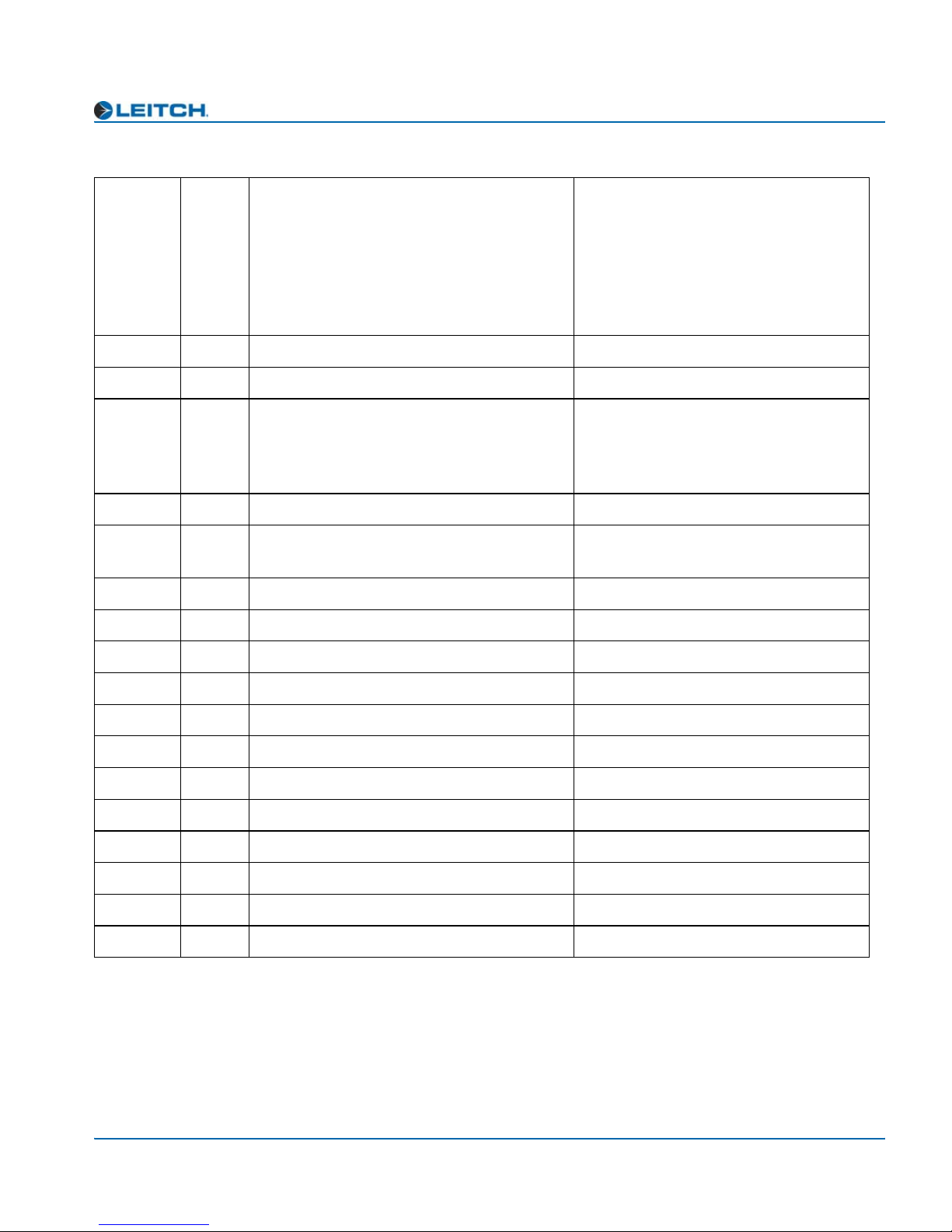
Table B-1. C-Bit Manipulation
Appendix B: Audio Bit Manipulation
2 3 to 5 [000] Not indicated
[001] Max Length - 1
Set to [100] if 16 bits; otherwise, set to
[101]
[010] Max Length - 2
[011] Max Length - 3
[100] Max Length - 4
[101] Max Length
[110] to [111] Undefined
2 6 to 7 Reserved Set to 0
3 0 to 7 Reserved Set to 0
4 0 to 1 [00] Not a reference
Set to 0
[01] Grade 1 reference
[10] Grade 2 reference
[11] Undefined
42Reserved Set to 0
4 3 to 6 Reserved Set to [0100] if SampleRate = 96 kHz;
otherwise, set to [0000]
47Reserved Set to 0
5 0 to 7 Reserved Set to 0
6 to 9 0 to 7 Alphanumeric channel origin data Set to 0
10 to 13 0 to 7 Alphanumeric channel destination data Set to 0
14 to 17 0 to 7 Local sample address code Set to 0
18 to 21 0 to 7 Time-of-day sample address code Set to 0
22 0 to 3 Reserved Set to 0
22 4 Bytes 0 to 5 reliability flag Set to 0
22 5 Bytes 6 to 13 reliability flag Set to 0
22 6 Bytes 14 to 17 reliability flag Set to 0
22 7 Bytes 18 to 21 reliability flag Set to 0
23 0 to 7 CRC Calculated on output
ADC-3981 Installation and Operation Manual 45

Appendix B: Audio Bit Manipulation
Validity and User Bits
Table B-2. V-Bit and U-Bit Manipulation
Bit Manipulation Function Remarks
Validity (V) Bit [0] Valid
[1] Invalid
User (U) Bit Set to 0
Set to 0
46 ADC-3981 Installation and Operation Manual

Keywords
Index
A
Add Upgrade Files box 11–17
AIB-25-MF adapter 5
alarms 27
All List and Operator List 23
analog audio specifications 34
–28
–25
B
back module 4
boot file 11
buying manuals ix
, 13–17
C
card-edge LED locations 30
causes of alarms 27
C-Bit manipulation 44
compliance and certification information x
Configuration... window 11
correcting a failed upgrade 15
cross-functional parameter changes 21
–17
–17
Discovery method of upgrading 11
drag-and-drop method of upgrading 13
–12
E
enabling or disabling alarms 28
external reference specifications 34
F
fail-safe procedure 15–17
FctryRcl parameters 20
firmware upgrading 11
fl0 folder 12
front module 3
functional block diagram 6
, 14, 17
, 23
–17
I
identifying causes of alarms 27
installing and removing modules 8
J
–14
D
default settings for alarms 28
DejaView 27
digital audio specifications 35
disabling or enabling alarms 28
ADC-3981 Installation and Operation Manual 47
jumper settings 9–10
L
LED descriptions 31
LEDs and module indicators 29
–32

Index
M
main features 2
manuals, purchasing ix
module indicator descriptions 32
module installation and removal 8
N
navigating parameter lists 22, 38
Navigation Properties box 13
, 16
O
Operator and All List 23–25
P
packing equipment for shipping ix
parameter lists
Operator and All 23
Tree View 39
parameters
FctryRcl 20
Setup 26
performance specifications 36
pinouts, back module 4
plug-in adapter 5
power consumption specifications 36
, 23
–25
–41
signal flow 6
Software Upgrade tab 11
specifications
analog audio 34
digital audio 35
external reference 34
performance 36
power consumption 36
start-up time 36
state recovery of alarms 27
synchronizing alarms 27
–17
, 28
T
Tree View parameter list 39–41
U
unpacking ix
upgrading firmware 11
–17
V
V-Bit and U-Bit manipulation 46
vxWorks.lzs file 12
, 14–15, 17
W
warranty information ii
Web site, location of manuals ix
R
rebooting the module 12, 14, 17
removing and installing modules 8
restoring default settings for alarms 28
returning equipment ix
revision history vii
S
safety standards and compliances x
setting jumpers 9
Setup parameters 26
shipping equipment ix
48 ADC-3981 Installation and Operation Manual
–10

 Loading...