

Page 1

Installation, Configuration, and
Operation Manual
IPA6800+
ASI on IP Video Gateway
Release 1.2.0 Revision A
May 2016
Page 2

IPA6800+ ASI on IP Video Gateway Installation, Configuration, and Operation Manual
Publication Information
© 2016 Imagine Communications Corp.
Proprietary and Confidential.
Imagine Communications considers this document and its contents to be proprietary and confidential.
Except for making a reasonable number of copies for your own internal use, you may not reproduce this
publication, or any part thereof, in any form, by any method, for any purpose, or in any language other
than English without the written consent of Imagine Communications. All others uses are illegal.
This publication is designed to assist in the use of the product as it exists on the date of publication of
this manual, and may not reflect the product at the current time or an unknown time in the future. This
publication does not in any way warrant description accuracy or guarantee the use for the product to
which it refers. Imagine Communications reserves the right, without notice to make such changes in
equipment, design, specifications, components, or documentation as progress may warrant to improve
the performance of the product.
Trademarks
Magellan CCS Navigator™, Selenio 6800+™ are trademarks or trade names of Imagine Communications
or its subsidiaries.
Microsoft® and Windows® are registered trademarks of Microsoft Corporation. All other trademarks and
trade names are the property of their respective companies.
Contact Information
Imagine Communications has office locations around the world. For domestic and international location
and contact information, visit our Contact page (http://www.imaginecommunications.com/howbuy/contact-us).
Support Contact Information
For domestic and international support contact information see:
Support Contacts (http://www.imaginecommunications.com/how-buy/contact-us)
Worldwide Support e-mail (mailto: [email protected])
Customer Community Portal (http://app.imaginecommunications.com/customercommunity)
Warranty & Contract Information (http://www.imaginecommunications.com/services/customer-
care)
MyImagine Academy Training (http://www.imaginecommunications-academy.com)
Product Manuals (http://www.imaginecommunications.com/services/product-manuals)
© 2016 Imagine Communications Corp. Proprietary and Confidential. Release 1.2.0 Revision A | Page 2
Page 3

IPA6800+
Installation, Configuration, and Operation Manual Contents
Contents
Preface ................................................................................................................... 5
Manual Information ................................................................................................................................. 5
Purpose ................................................................................................................................................. 5
Audience ............................................................................................................................................... 5
Writing Conventions ............................................................................................................................. 5
Obtaining Documents ........................................................................................................................... 6
Unpacking/Shipping Information ............................................................................................................. 6
Unpacking a Product ............................................................................................................................ 6
Product Servicing .................................................................................................................................. 6
Returning a Product ............................................................................................................................. 6
Safety ........................................................................................................................................................ 7
Safety Terms and Symbols in this Manual ........................................................................................... 7
Restriction on Hazardous Substances (RoHS) Compliance ....................................................................... 7
Waste from Electrical and Electronic Equipment (WEEE) Compliance .................................................... 8
IPA6800+ Module and I/O Interface ...................................................................... 9
Overview ................................................................................................................................................... 9
Module Description ................................................................................................................................ 10
IPA6800++R Back Connector .............................................................................................................. 10
IPA6800+ Front Module ..................................................................................................................... 11
Electrical Interfaces ................................................................................................................................ 12
ASI Out ................................................................................................................................................ 12
ASI In ................................................................................................................................................... 12
Ethernet Interface .............................................................................................................................. 13
Signal Flow .............................................................................................................................................. 13
Part Numbers.......................................................................................................................................... 14
Installation and Navigator Discovery .................................................................... 15
Maximum 6800+ Frame Power Ratings ................................................................................................. 15
How to Prepare the Product for Installation .......................................................................................... 15
Module Information ............................................................................................................................... 16
Required Frames and Back Connector Types ..................................................................................... 16
Installing and Removing Application Modules ................................................................................... 16
© 2016 Imagine Communications Corp. Proprietary and Confidential. Release 1.2.0 Revision A | Page 3
Page 4

IPA6800+
Installation, Configuration, and Operation Manual Contents
How to Perform a Discovery of the Module in Navigator .................................................................. 16
Firmware Upgrade ............................................................................................... 18
Procedure ............................................................................................................................................... 18
How to Monitor a Software Upgrade ..................................................................................................... 19
Operation ............................................................................................................ 21
How Commands Are Documented for Both Craft and Navigator .......................................................... 21
Navigator Configuration Recommendation ........................................................................................... 21
General Operating Procedures ............................................................................................................... 22
How Parameter Changes are Applied ................................................................................................ 22
How to Check Hardware and Software Versions ............................................................................... 23
Configuration Procedures ....................................................................................................................... 23
How to Transmit Video Over an IP Stream ........................................................................................ 23
How to Extract Video from an IP Stream ........................................................................................... 24
How to Monitor Module Alarms ........................................................................................................ 24
Configuration and Status Parameters .................................................................. 25
Overview ................................................................................................................................................. 25
Command Groups ................................................................................................................................... 25
IPA6800+ Parameters ............................................................................................................................. 25
How to Use Telnet .............................................................................................................................. 25
Parameter Usage Notes ..................................................................................................................... 25
Remote Control Parameters............................................................................................................... 26
Status Parameters .............................................................................................................................. 27
Utility Commands ............................................................................................................................... 28
Alarm Commands ............................................................................................................................... 29
Specifications ....................................................................................................... 30
Electrical Specifications .......................................................................................................................... 30
Physical Specifications ............................................................................................................................ 30
Regulatory Compliance........................................................................................................................... 31
Software Communication Problems .................................................................... 32
Hardware Communication Problems ................................................................... 35
© 2016 Imagine Communications Corp. Proprietary and Confidential. Release 1.2.0 Revision A | Page 4
Page 5
IPA6800+
Term or Convention
Description
Bold
Indicates dialog box, property sheet, field, button, check box,
list box, combo box, menu, submenu, window, list, and
selection names
Italics
Indicates email addresses, names of books and publications,
and first instances of new terms and specialized words that
need emphasis
CAPS
Indicates a specific key on the keyboard, such as ENTER, TAB,
CTRL, ALT, DELETE
Code
Indicates variables or command-line entries or something you
type into a field.
>
Indicates the direction of navigation through a hierarchy of
menus and windows
hyperlink
Indicates a jump to another location within the electronic
document or elsewhere
Internet address
Indicates a jump to a Web site or URL
Installation, Configuration, and Operation Manual Preface
Preface
Manual Information
Purpose
This manual details the features, installation, operation, maintenance, and specifications for the
IPA6800+.
Audience
This manual is written for engineers, technicians, and operators responsible for installation, setup,
maintenance, and/or operation of the IPA6800+.
Writing Conventions
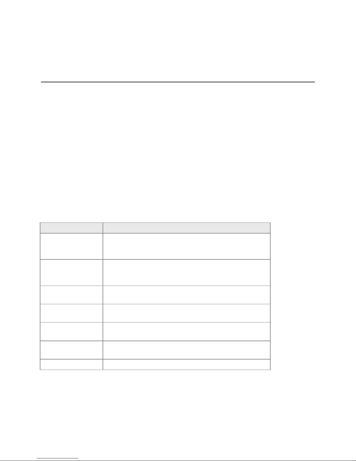
This manual adheres to the following writing conventions.
© 2016 Imagine Communications Corp. Proprietary and Confidential. Release 1.2.0 Revision A | Page 5
Page 6

IPA6800+
Installation, Configuration, and Operation Manual Preface
Obtaining Documents
Product support documents can be viewed or downloaded from our website. Alternatively, contact your
Customer Service representative to request a document.
Unpacking/Shipping Information
Unpacking a Product
This product was carefully inspected, tested, and calibrated before shipment to ensure years of stable
and trouble-free service.
1. Check equipment for any visible damage that may have occurred during transit.
2. Confirm that you have received all items listed on the packing list.
3. Contact your dealer if any item on the packing list is missing.
4. Contact the carrier if any item is damaged.
5. Remove all packaging material from the product and its associated components before you install
the unit.
Keep at least one set of original packaging, in the event that you need to return a product for servicing.
Product Servicing
Except for firmware upgrades, modules are not designed for field servicing. All hardware upgrades,
modifications, or repairs require you to return the modules to the Customer Service center.
Returning a Product
In the unlikely event that your product fails to operate properly, please contact Customer Service to
obtain a Return Authorization (RA) number, and then send the unit back for servicing.
Keep at least one set of original packaging in the event that a product needs to be returned for service.
If the original package is not available, you can supply your own packaging as long as it meets the
following criteria:
The packaging must be able to withstand the product’s weight.
The product must be held rigid within the packaging.
There must be at least 2 in. (5 cm) of space between the product and the container.
The corners of the product must be protected.
Ship products back to us for servicing prepaid and, if possible, in the original packaging material. If the
product is still within the warranty period, we will return the product prepaid after servicing.
© 2016 Imagine Communications Corp. Proprietary and Confidential. Release 1.2.0 Revision A | Page 6
Page 7
IPA6800+
WARNING
Statements identifying conditions or practices that may result in
personal injury or loss of life. High voltage is present.
CAUTION
Statements identifying conditions or practices that can result in
damage to the equipment or other property.
Installation, Configuration, and Operation Manual Preface
Safety
Carefully review all safety precautions to avoid injury and prevent damage to this product or any
products connected to it. If this product is rack-mountable, it should be mounted in an appropriate rack
using the rack-mounting positions and rear support guides provided. It is recommended that each frame
be connected to a separate electrical circuit for protection against circuit overloading. If this product
relies on forced air cooling, it is recommended that all obstructions to the air flow be removed prior to
mounting the frame in the rack.
If this product has a provision for external earth grounding, it is recommended that the frame be
grounded to earth via the protective earth ground on the rear panel.
IMPORTANT! Only qualified personnel should perform service procedures.
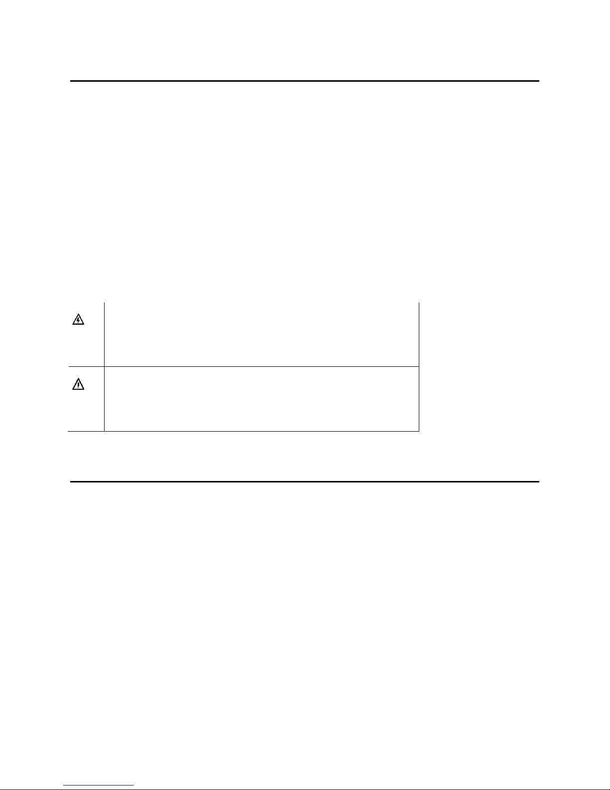
Safety Terms and Symbols in this Manual
Restriction on Hazardous Substances (RoHS)
Compliance
Directive 2011/65/EU (RoHS 2)—commonly known as the European Union (EU) Restriction on
Hazardous Substances (RoHS)—sets limits on the use of certain substances found in electrical and
electronic equipment. The intent of this legislation is to reduce the amount of hazardous chemicals that
may leach out of landfill sites or otherwise contaminate the environment during end-of-life recycling.
The Directive, which took effect on July 1, 2006, refers to the following hazardous substances:
Lead (Pb)
Mercury (Hg)
Cadmium (Cd)
Hexavalent Chromium (Cr-V1)
Polybrominated Biphenyls (PBB)
Polybrominated Diphenyl Ethers (PBDE)
© 2016 Imagine Communications Corp. Proprietary and Confidential. Release 1.2.0 Revision A | Page 7
Page 8
IPA6800+
Installation, Configuration, and Operation Manual IPA6800+ Module and I/O Interface
According to this EU Directive, all products sold in the European Union will be fully RoHS-compliant and
“lead-free.” (See our website for more information.) Spare parts supplied for the repair and upgrade of
equipment sold before July 1, 2006 are exempt from the legislation. Equipment that complies with the
EU directive will be marked with a RoHS-compliant emblem.
Waste from Electrical and Electronic
Equipment (WEEE) Compliance
The European Union (EU) Directive 2002/96/EC on Waste from Electrical and Electronic Equipment
(WEEE) deals with the collection, treatment, recovery, and recycling of electrical and electronic waste
products. The objective of the WEEE Directive is to assign the responsibility for the disposal of
associated hazardous waste to either the producers or users of these products. As of August 13, 2005,
the producers or users of these products were required to recycle electrical and electronic equipment at
end of its useful life, and may not dispose of the equipment in landfills or by using other unapproved
methods. (Some EU member states may have different deadlines.)
In accordance with this EU Directive, companies selling electric or electronic devices in the EU will affix
labels indicating that such products must be properly recycled. (See our website for more information.)
Contact your local sales representative for information on returning these products for recycling.
Equipment that complies with the EU directive will be marked with a WEEE-compliant emblem.
© 2016 Imagine Communications Corp. Proprietary and Confidential. Release 1.2.0 Revision A | Page 8
Page 9

IPA6800+
Installation, Configuration, and Operation Manual IPA6800+ Module and I/O Interface
IPA6800+ Module and I/O Interface
Overview
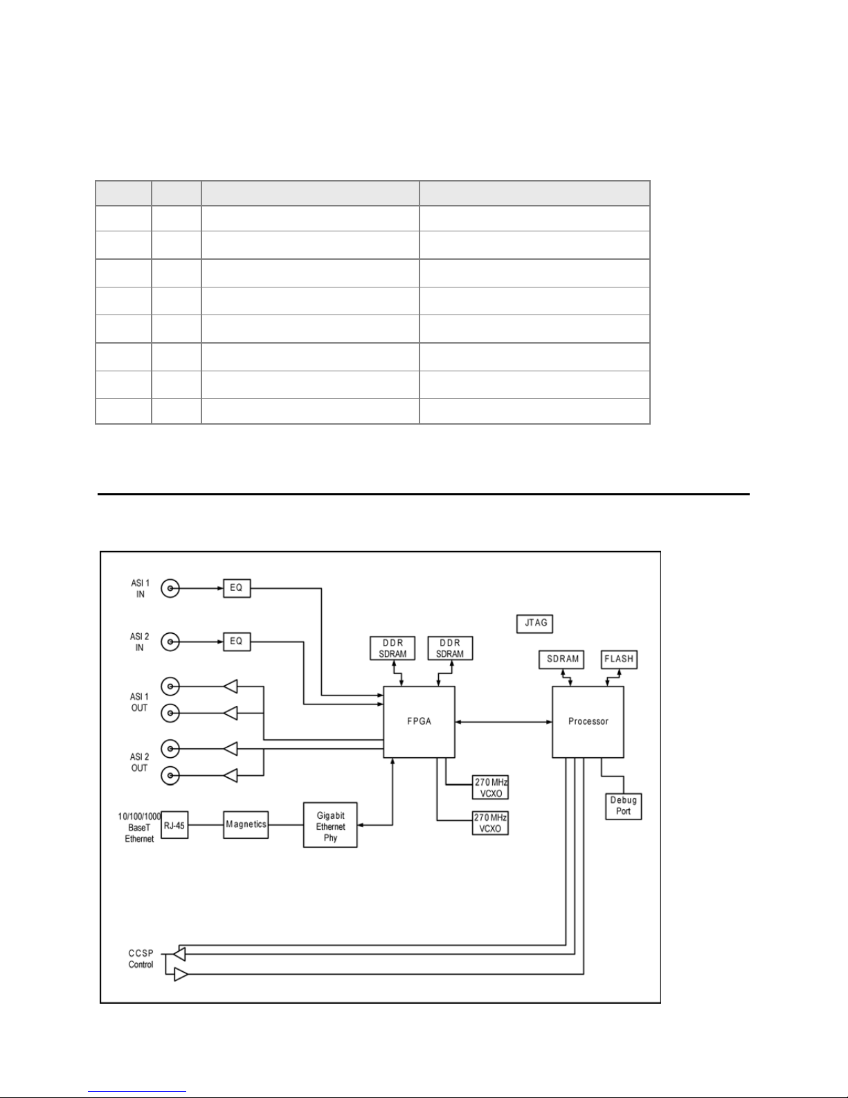
The IPA6800+ ASI on IP Video Gateway is part of Imagine Communications' 6800+ series of processing
and conversion modules.
IPA6800+ ASI on IP Video Gateway performs the following functions.
Encapsulates ASI into Gigabit Ethernet.
De-encapsulates ASI from Gigabit Ethernet.
Transmit Mode
In transmission mode, the IPA6800+ maps ASI into IP packets and applies Forward Error Correction (FEC)
to ensure the highest possible level of quality in network throughput.
Receive Mode
In receive mode, the IPA6800+ receives IP and uses Forward Error Correction (FEC) as needed, to
reconstruct the original ASI stream.
The IPA6800+ provides a card edge control for basic Ethernet IP address provisioning. Thereafter the
provisioning process may b e completed using Magellan CCS Navigator or Navigator provisioned with
the board’s IP address.
It offers:
Two (2) ASI video inputs conforming to DVB-ASI A011 Rev 1.0
Four (4) ASI video outputs. Outputs are paired. Each pair of BNCs presents the same signal on two
interfaces.
One (1) 1000 BaseT Ethernet Interface
© 2016 Imagine Communications Corp. Proprietary and Confidential. Release 1.2.0 Revision A | Page 9
Page 10
IPA6800+
Item
Description
Full Description
1
ASI Input 1 & Input 2
Receives DVB-ASI-compliant transport stream input
2 & 3
ASI Outputs 1 & 2
Provides DVB-ASI transport stream output
4 - Not Used
5
100 BaseT Ethernet
Installation, Configuration, and Operation Manual IPA6800+ Module and I/O Interface
Module Description
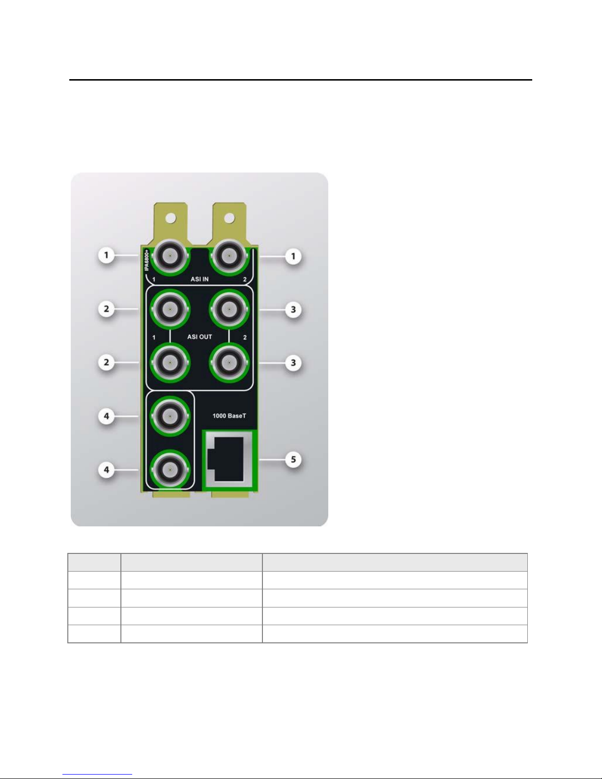
IPA6800++R Back Connector
The IPA6800++R double-slot back connector is used by the IPA6800+ when installed in a FR6802+ frame.
Table 1:
© 2016 Imagine Communications Corp. Proprietary and Confidential. Release 1.2.0 Revision A | Page 10
Page 11
IPA6800+
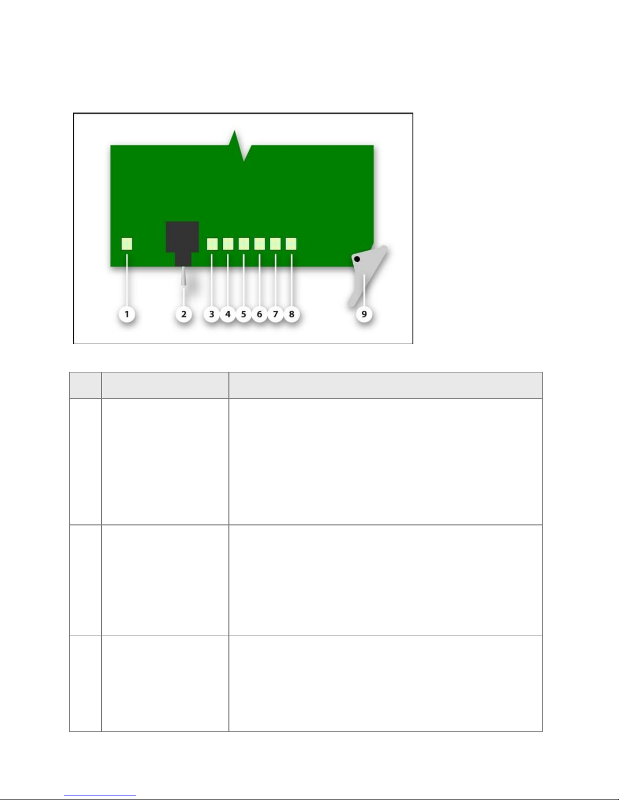
Feature
Description
1
Module Status LED
Indicates the module’s state of operation.
Off: The module is powered OFF. The module is not operational.
Red: The module is either booting or experiencing an error
Red (blinking): The module has booted in ‘safe mode’. See
‘Toggle Switch’ description below.
Amber: The module is booting
Green: The module is powered ON. The module is operating
properly.
2
Toggle Switch
This three-position toggle switch controls the card’s IP address
configuration.
Up (after boot): Forces the IP address for Telnet configuration
and control to 192.168.1.1
Up (at boot): Forces the module into ‘safe mode’
Center: The module operates using the configured IP address
Down: Disables Telnet access
3, 4
ASI LEDs
Each LED indicates the state of an ASI input interface.
Off: The module is powered Off or the interface is not configured
for use
Red: Loss of Signal (LOS) is detected
Amber: Errors are detected on the interface
Green: The interface is operating normally
Installation, Configuration, and Operation Manual IPA6800+ Module and I/O Interface
IPA6800+ Front Module
Table 2: IPA6800+ Front Module Card Edge Features
© 2016 Imagine Communications Corp. Proprietary and Confidential. Release 1.2.0 Revision A | Page 11
Page 12

IPA6800+
Feature
Description
5 - Not used
6
Error LED
Green: The module is operating normally
Red: An encapsulator or decapsulator alarm condition has
occurred within the last five seconds
7
Ethernet Speed LED
Indicates the Ethernet interface’s state of operation
Off: The Ethernet interface is either negotiating or experiencing
an LOS. Use the LINK LED below to fully identify the actual state
Green: The Ethernet interface is operating in 1000 BaseT mode.
Red: The Ethernet Interface is attempting to operate in half-
duplex mode or is operating in full-duplex at 10 Mbps
Amber: The Ethernet interface is operating in 100 BaseT mode
8
Ethernet Link LED
Indicates the Ethernet interface’s state of operation.
Off: The module is powered Off. The module is not operational.
Red: Indicates the interface is experiencing an LOS.
Green The Ethernet interface has established link-level
connectivity.
Amber The Ethernet interface is negotiating.
9
Ejector Handle
Used to eject the module from the 6800+.
Installation, Configuration, and Operation Manual IPA6800+ Module and I/O Interface
Electrical Interfaces
ASI Out
The IPA6800+ can simultaneously provide two unique ASI signals. Each such signal is presented on two
BNC outputs. All ASI connections require 75-Ohm characteristic impedance coaxial cable. In general,
reliable operation can be achieved with cable lengths of up to 100 meters.
ASI In
The IPA6800+ can simultaneously receive two unique ASI signals. Each such signal is received through
either the ‘ASI 1 IN’ or the ‘ASI 2 IN’ interface. These two input interfaces support each ASI signal that
the IPA6800+ can put on IP. All ASI connections require 75-Ohm characteristic impedance coaxial cable.
In general, reliable operation can be achieved with cable lengths of up to 100 meters.
© 2016 Imagine Communications Corp. Proprietary and Confidential. Release 1.2.0 Revision A | Page 12
Page 13
IPA6800+
Item
Pin
1000 BaseT
10/100 BaseT
1 1 Bi-directional Data A+
Transmit +
2 Bi-directional Data A
Transmit -
3 Bi-directional Data B+
Receive +
4 Bi-directional Data C+
-
5
Bi-directional Data C
- 6
Bi-directional Data B
Receive -
7
Bi-directional Data D+
--
8 8 Bi-directional Data D
Installation, Configuration, and Operation Manual IPA6800+ Module and I/O Interface
Ethernet Interface
Table 3: 1000 BaseT Ethernet Pin Out
Signal Flow
© 2016 Imagine Communications Corp. Proprietary and Confidential. Release 1.2.0 Revision A | Page 13
Page 14

IPA6800+
Part Number
Description
IPA6800+D
ASI on IP Video Gateway – Bi-Directional Dual ASI to IP converter kit.
Complete kit includes:
One (1) IPA6800+ ASI on IP Video Gateway – Front Application Module
One (1) IPA6800+R ASI on IP Video Gateway – Rear Connector Module
IPA6800+
ASI on IP Video Gateway – Front Application Module:
Provides two (2) bi-directional (ASI to IP/IP to ASI) channels
IPA6800+R
ASI on IP Video Gateway – Rear Connector Module: Provides I/O for the
IPA6800+. Includes:
Two (2) ASI BNC Inputs
Four (4) ASI BNC Output Connectors (two identical signals for each
output channel)
One (1) Gigabit Ethernet Jack
Installation, Configuration, and Operation Manual IPA6800+ Module and I/O Interface
Part Numbers
© 2016 Imagine Communications Corp. Proprietary and Confidential. Release 1.2.0 Revision A | Page 14
Page 15
IPA6800+
6800+ Frame Type
Max Frame Power
Dissipation
Number of Usable
Slots
Max Power
Dissipation per Slot
6800+XF – Frame with AC power supply
120 W
20
6 W
6800+XF – Frame with DC power supply
105 W
20
5.25 W
IPA6800+
One IPA6800+ front application module
One double-slot back connector
One documentation and firmware CD
Installation, Configuration, and Operation Manual Installation and Navigator Discovery
Installation and Navigator Discovery
Caution: Before installing this product, read the 6800+ Series Safety Instructions and Standards Manual
shipped with every FR6802+ Frame Installation and Operation Manual or downloadable from our
website. This safety manual contains important information about the safe installation and operation of
6800+ series products.
This section describes the IPA6800+ installation process. See the FR6802+ Frame Installation and
Operation Manual for information about installing and operating a 6800+ frame and its components.
Maximum 6800+ Frame Power Ratings
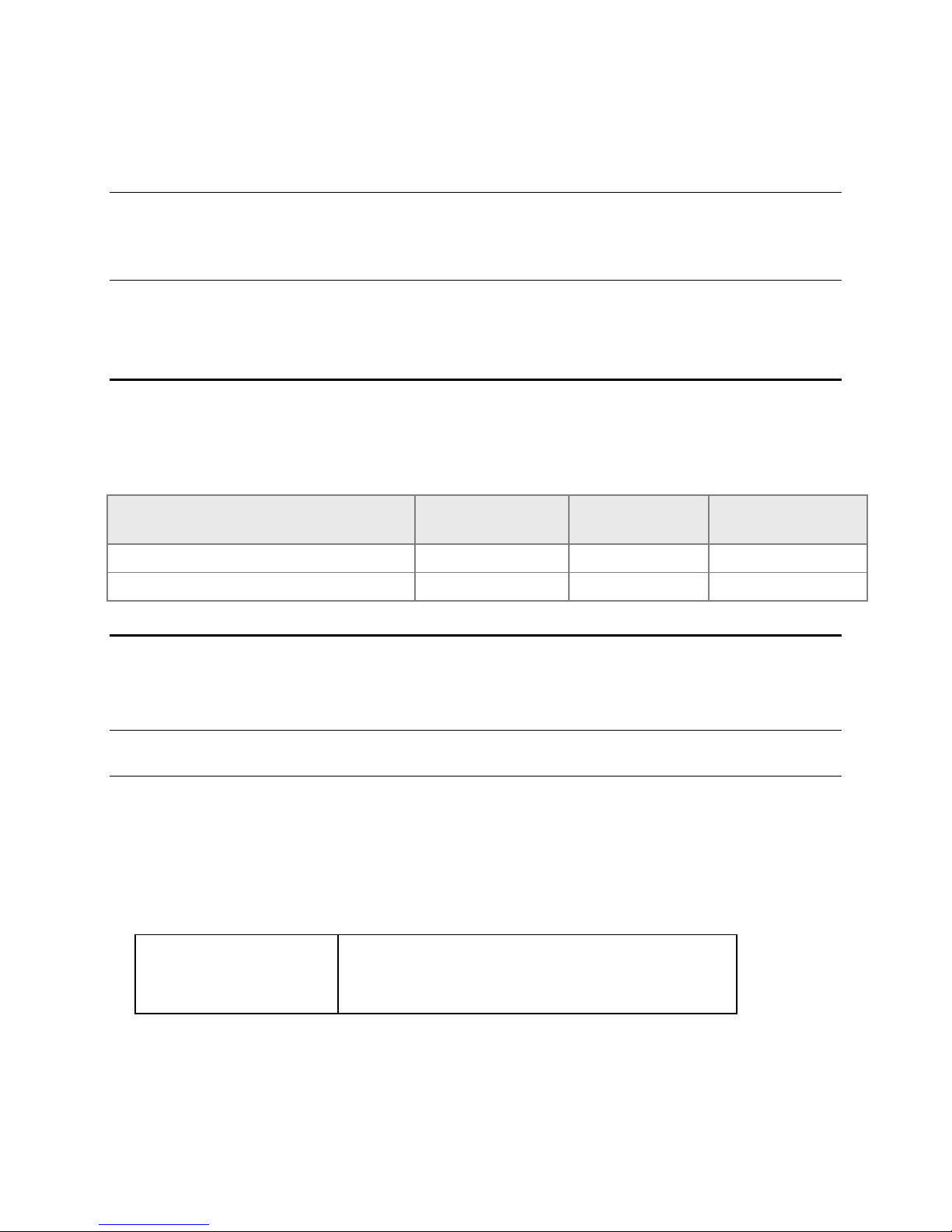
This table describes the maximum allowable power ratings for 6800+ frames. Note the given maximums
before installing any 6800+ modules in your frame.
How to Prepare the Product for Installation
Perform the following steps before installing the IPA6800+.
Note: Contact your Customer Service representative if parts are missing or damaged Contact your
Customer Service representative if parts are missing or damaged.
1. Unpack the module
2. Check the equipment for any visible damage that may have occurred during transit.
3. Confirm receipt of all items on the packing list. The following items should be included.
4. Remove the anti-static shipping pouch, if present, and all other packaging material
5. Remove the anti-static shipping pouch, if present, and all other packaging material
See Unpacking/Shipping Information (on page 6) for information about returning a product for servicing.
© 2016 Imagine Communications Corp. Proprietary and Confidential. Release 1.2.0 Revision A | Page 15
Page 16

IPA6800+
Installation, Configuration, and Operation Manual Installation and Navigator Discovery
Module Information
Required Frames and Back Connector Types
The IPA6800+ module has a double-width back connector that can be installed in a 6800+XF. See the
6800+ Frame Installation and Operation Manual for installing back connectors in a 6800+ frame.
Installing and Removing Application Modules
These modules require no specialized installation or removal procedures. However, if installing both
front and rear modules, ensure that the back module is installed first before plugging in the front
module. When removing both the front and rear modules, ensure that the front module is unplugged
from the frame first, before removing the rear module.
See the 6800+ Frame Installation and Operation Manual for information about installing and
operating a 6800+ frame and its components.
See the 6800+ Safety Instructions and Standards Manual for important information about safely
installing your module.
Once the IPA6800+ module is installed, the appropriate input and output cables can be connected.
How to Perform a Discovery of the Module in Navigator
Use this procedure to cause Navigator to ‘Discover’ a recently-installed module.
1. Click Options > Discovery to open the Discovery Options dialog.
2. If the Products for Discovery column lists the frame containing the module you have just installed
(Note: Check the IP Address column as well to be sure) then…
a. Place a check mark in the Hosts column next to the module.
b. Click the Apply button, then click the OK button.
c. Skip to Step 4 below
3. If the frame of containing the module you have just installed is not listed, then click the Add…
button to open the Add Host dialog.
a. Enter the IP Address of the 6800-series shelf in the Host IP field.
b. Click the Options… button to open the Communication Settings dialog.
Choose the ‘Point-to-Point’ option from the Communication Type drop-down.
Click OK to dismiss the Communications Settings dialog.
c. Click OK to dismiss the Add Host dialog.
4. Click OK to dismiss the Discovery Options dialog.
5. If the Discovery Pane is not visible, click Tools > Discovery to reveal it.
6. Click the Start button to begin the Discovery session.
7. Wait until the Status window indicates “Discovery Completed”.
8. Click the Save button.
© 2016 Imagine Communications Corp. Proprietary and Confidential. Release 1.2.0 Revision A | Page 16
Page 17

IPA6800+
Installation, Configuration, and Operation Manual Installation and Navigator Discovery
9. Drag the icons of any discovered pieces of equipment from the Discovery branch to of the
navigation tree to the Network branch.
10. Click the Save button to save the discovered items as network elements.
The discovered items are now ready for further configuration and monitoring.
© 2016 Imagine Communications Corp. Proprietary and Confidential. Release 1.2.0 Revision A | Page 17
Page 18
IPA6800+
Installation, Configuration, and Operation Manual Firmware Upgrade
Firmware Upgrade
If a previous upgrade was interrupted and the module will not boot correctly, or if the module is in an
inoperable state
1. Move the toggle switch to the ‘up’ position.
2. Re-insert the module to cause it to boot in ‘safe mode’.
3. Proceed with the following upgrade procedure.
4. When the upgrade procedure is completed, move the toggle switch back to the ‘center’ position.
Procedure
1. Install the appropriate upgrade package from the CD-ROM or download it from the Imagine
Communications portal.
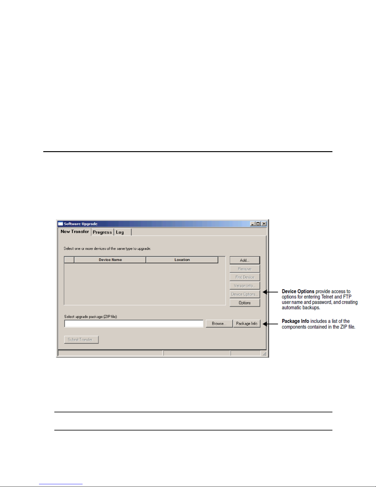
2. In Navigator, choose Tools > Software Upgrade. The Software Upgrade dialog opens and is brought
into the foreground.
3. On the New Transfer tab, click the Add button on the right. The Device Selection dialog opens.
4. In the Device Selection dialog
Expand the tree as needed to reveal the target device
Highlight the target device.
Click OK to close the Add Device dialog box.
Note: All items in a frame have the same IP address. Only one device from each IP address can be
added.
5. In the Software Upgrade dialog, click the Browse... button to open a standard Windows File
Selection dialog.
© 2016 Imagine Communications Corp. Proprietary and Confidential. Release 1.2.0 Revision A | Page 18
Page 19
IPA6800+
Installation, Configuration, and Operation Manual Firmware Upgrade
6. In the Windows File Selection dialog…
Select the software upgrade package (ZIP file) on either a local or a network drive.
Click the Open button to close the File Selection dialog and to populate the full path name to the
upgrade zip package.
Note: The extraction process on the ZIP file is handled as part of the upgrade process. There is no
need to manually extract these files.
7. Press Submit Transfer... button. A dialog box opens, requesting confirmation to proceed with the file
transfer request…
8. Click Yes confirm the file transfer and to begin the upgrade process.
If multiple devices are selected, then multiple transfer tasks (one per device) begin.
At this point, the Software Upgrade window may be closed and the PC used for other tasks. Closing
the Software Upgrade window does not affect any transfer processes that may be running in the
background. However, if you try to log off or exit the CCS software while a transfer is underway, a
notification window will alert you that processes are still active and will ask if you want to terminate
these processes.
9. See How to Monitor a Software Upgrade (on page 19) for details on how to track upgrade progress
and how to confirm when the upgrade process has completed.
How to Monitor a Software Upgrade
Use this procedure to monitor the status of a software upgrade.
The Software Upgrade dialog offers two mechanisms, the Log Tab and the Progress Tab for determining
the status of an upgrade once it has begun.
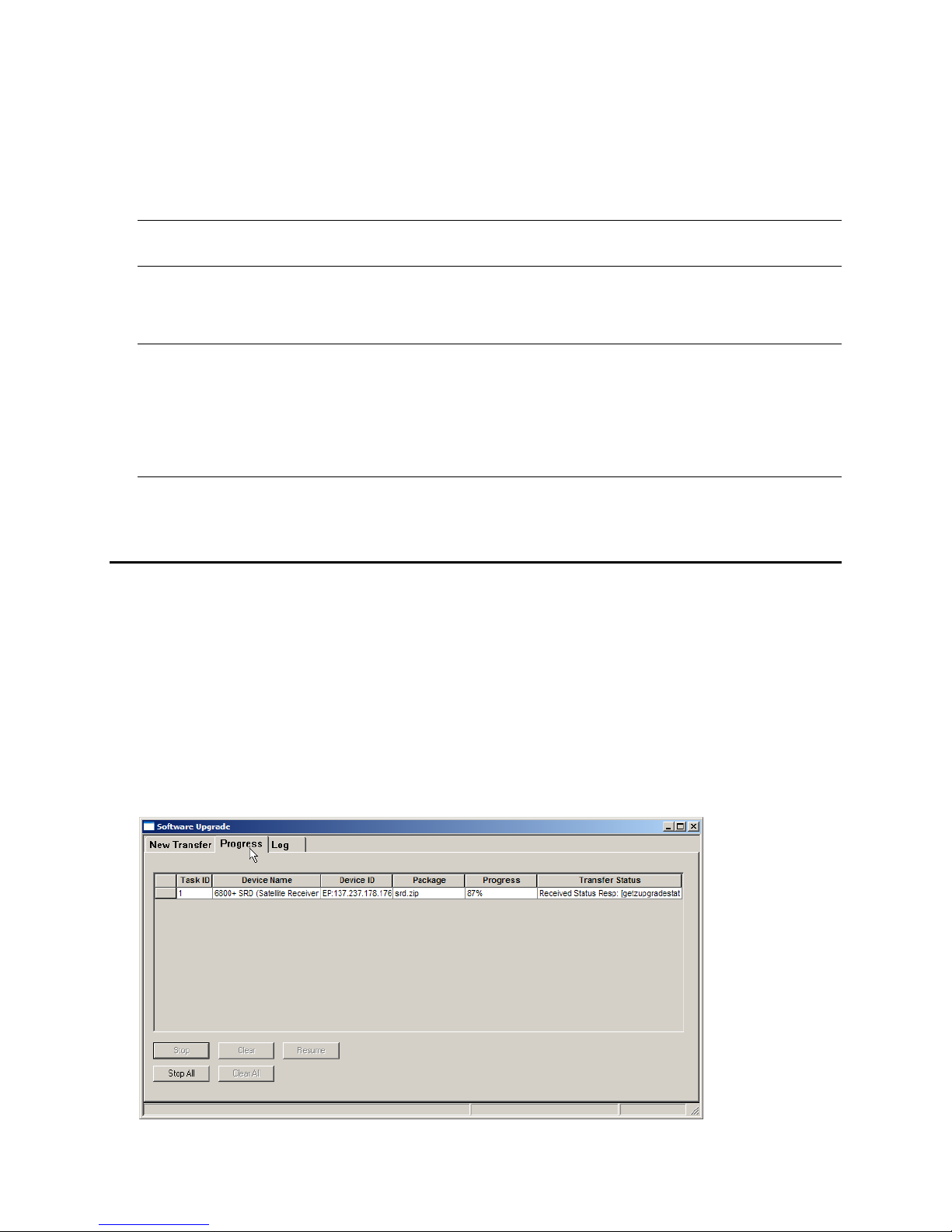
1. The Progress Tab provides a table with one row identifying each device scheduled to receive and
upgrade.
The Progress column indicates the current status of any ongoing transfers.
The Transfer Status column indicates the overall success or the failure of each transfer attempt.
© 2016 Imagine Communications Corp. Proprietary and Confidential. Release 1.2.0 Revision A | Page 19
Page 20
IPA6800+
Installation, Configuration, and Operation Manual Firmware Upgrade
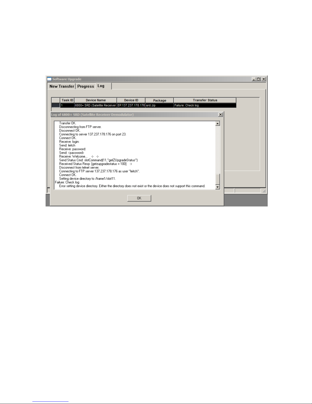
2. The Log Tab provides Pass/Fail status on all file transfer attempts
In the event of a failure of any kind, double-click on the row indicating the failure to open the
Log.
Scroll down to the bottom of the Log to view the last failed action.
© 2016 Imagine Communications Corp. Proprietary and Confidential. Release 1.2.0 Revision A | Page 20
Page 21

IPA6800+
Installation, Configuration, and Operation Manual Operation
Operation
How Commands Are Documented for Both
Craft and Navigator
In Navigator, each element in this command line represents a distinct level in the command tree. The
last element in the command line represents a parameter value selection or entry.
Procedures in this chapter list commands in a single-line format.
Configuration/Ethernet/IP Address = 123.123.123.123
An expansion of this example instruction would appear as follows.
1. Select the ‘Configuration’ branch in Navigator
2. Select the ‘Ethernet’ branch.
3. Choose the ‘IP Address’ parameter.
4. Set the ‘IP Address’ parameter to ‘123.123.123.123’.
See the Magellan CCS Navigator, or RCP-CCS-1U Remote Control Panel manual for Ethernet interface
documents for information on how to operate this product remotely.
Navigator Configuration Recommendation
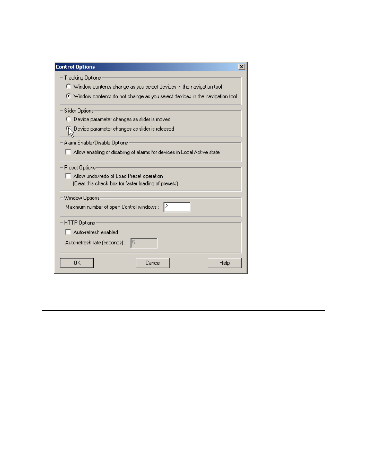
We recommend the following setting in Navigator to ensure fast and accurate communication with the
IPA6800+.
© 2016 Imagine Communications Corp. Proprietary and Confidential. Release 1.2.0 Revision A | Page 21
Page 22
IPA6800+
Installation, Configuration, and Operation Manual Operation
1. In Navigator, choose “Options > Control” to open the ‘Control Options’ dialog
2. Check the ‘Device parameter changes as slider is released’ radio button.
3. Click the ‘OK’ button
General Operating Procedures
How Parameter Changes are Applied
Observe the following when setting the configuration parameters on the IPA6800+:
Parameter changes take immediate effect. However, the module requires up to 30 seconds to save
the latest change.
After 30 seconds, the new settings are saved. Once saved, these will be restored in the event the
module loses power or is restarted
© 2016 Imagine Communications Corp. Proprietary and Confidential. Release 1.2.0 Revision A | Page 22
Page 23

IPA6800+
Installation, Configuration, and Operation Manual Operation
How to Check Hardware and Software Versions
Use Navigator to determine the module’s current hardware or software version.
See the RCP-CCS-1U Installation and Operation Manual, CCS software application user manual, or CCS
software application online help for information on viewing software and hardware version numbers.
Configuration Procedures
How to Transmit Video Over an IP Stream
Use the examples shown in this procedure to configure the IPA6800+ to encapsulate an ASI stream into
an IP packet stream.
1. Specify the input port and signal type.
Configuration/Encapsulator_2/Input = ASI
2. Forward Error Correction (FEC).
a. If FEC is desired, then specify the FEC type.
Configuration/Encapsulator_1/FEC Type = Medium
Configuration/Encapsulator_2/FEC Type = High
b. If FEC is not desired, then ensure that FEC is disabled.
Configuration/Encapsulator_1/FEC Type = None
Configuration/Encapsulator_2/FEC Type = None
3. If custom FEC if desired, then use the following parameters with your own values.
Configuration/Encapsulator_2/ASI FEC/…
Period = 20
Order = 10
Packets = 6
RTP = Enable
4. Configure the destination IP outputs
Each of the IPA6800+’s two inputs can be duplicated to up to four IP destinations.
Each destination is a ‘Conventional IP Address’ with an (optional) IP port.
Configure the following parameters to specify a ‘Conventional IP Address’ destination. The IP port is
optional.
Configuration/Encapsulator_#/Dest_#/…
IP Address = ###.###.###.###
Port = (0 to 65535)
5. Set the following parameters for each destination used on each interface.
Configuration/Encapsulator_#/Dest_#/…
TOS = (0 to 15)
© 2016 Imagine Communications Corp. Proprietary and Confidential. Release 1.2.0 Revision A | Page 23
TTL = (1 to 255)
Page 24

IPA6800+
Installation, Configuration, and Operation Manual Operation
How to Extract Video from an IP Stream
Use this procedure to configure the IPA6800+ to recover an ASI stream from an IP packet stream.
1. Specify the packet length for an ASI output.
Configuration/Decapsulator_1/ASI Pkt Len = (188,204)
2. Configure the input source
Note: If the source is providing a unicast then only the Port # (in the following steps) is required. The
other parameters may be left ignored.
a. Configure the source IP address and port (if necessary).
Configuration/Decapsulator_1/Source/…
Source IP = ###.###.###.###
– OR –
Multicast Group = ###.###.###.###
Port = (0–65535)
How to Monitor Module Alarms
IPA6800+’s Module Status LED illuminates red when an alarm condition is present.
Navigator can be configured to monitor an IPA6800+ module. As such, the software aggregates alarm
messages and presents them in a manner that distinguishes between major and minor alarms. See the
appropriate software control user manual or online help for more information
© 2016 Imagine Communications Corp. Proprietary and Confidential. Release 1.2.0 Revision A | Page 24
Page 25

IPA6800+
Installation, Configuration, and Operation Manual Configuration and Status Parameters
Configuration and Status Parameters
Overview
Use CCS control software such as Navigator, or Telnet to access IPA6800+ parameters. For Navigator,
see the software user manual for usage information.
Command Groups
IPA6800+ parameters are arranged into the following groups:
Configuration Commands
Status Commands
Utility Commands
Alarm Commands
IPA6800+ Parameters
How to Use Telnet
1. On a Windows PC, click the ‘Start > Run’, type the following and press ‘Return’ to open a DOS dialog
box.
cmd
2. Begin a Telnet session by using the system’s IP address and typing the following into the DOS dialog
box.
telnet <system IP Address>
3. The system prompts for a username and password. The following username and password are
factory defaults.
username: admin
password: admin
4. Once a Telnet connection is established, commands listed in the following sections can be directly
executed
Parameter Usage Notes
Many of the ‘Command Paths’ in the following sections depict a range of values in square brackets ‘[ ]’.
Configuration/Encapsulator_[1–2]/FEC Type
Substitute one value from the range to create a command string.
© 2016 Imagine Communications Corp. Proprietary and Confidential. Release 1.2.0 Revision A | Page 25
Page 26

IPA6800+
COMMAND PATH
DESCRIPTION
OPTIONS
DEFAULT
Configuration/Ethernet
Configuration/Ethernet/Link
Specifies the Ethernet
interface's link speed
auto, 10, 100, 1000
auto
Configuration/Ethernet/IP Address
Specifies the Ethernet
interface’s IP address
IP Address
192.168.1.1 (default)
0.0.0.0
Configuration/Ethernet/IP Mask
Specifies the Ethernet
interface's IP mask.
IP Address
255.255.255.0
(default)
0.0.0.0
Configuration/Ethernet/IP Gateway
Specifies the Ethernet
Interface's IP gateway
address.
IP Address
0.0.0.0
Configuration/Control
Configuration/Control/Password
Specifies the password
protecting the module's
control interfaces
31-char
admin
Configuration/Control/Telnet
Enables/disables the
module's Telnet
interface.
enable, disable
enable
Configuration/Encapsulator_[1–2]
Configuration/Encapsulator_[1–2]/Input
Enables/disables the
specified encapsulator
input and input type
OFF, AUTO, ASI,
off
Configuration/Encapsulator_[1–2]/FEC Type
Specifies the level/type
of FEC to apply to
outgoing data.
None, LOW,
MEDIUM, HIGH,
CUSTOM
low
Configuration/Encapsulator_[1–2]/Dest
Configuration/Encapsulator_[1–2]/Dest_[1–4]/IP
Address
Specifies the IP
destination address
0.0.0.0 (disables
destination)
0.0.0.0
Configuration/Encapsulator_[1–2]/Dest_[1–4]/Port
Specifies the IP
destination port.
0–65535
0
Configuration/Encapsulator_[1–2]/Dest_[1–4]/TOS
Specifies the Type of
Service (TOS) byte.
0–15
0
Configuration/Encapsulator_[1–2]/Dest_[1–4]/TTL
Specifies the packet
Time To Live (TTL).
1–255
16
Configuration/Encapsulator_[1–2]/ASI FEC
Configuration/Encapsulator_[1–2]/ASI FEC/Period
Sets the FEC period.
1–20
1
Configuration/Encapsulator_[1–2]/ASI FEC/Order
Sets the FEC Order
4–20
16
Installation, Configuration, and Operation Manual Configuration and Status Parameters
Configuration/Encapsulator_1/FEC Type
Configuration/Encapsulator_2/FEC Type
Add an equals sign ‘=’ and value from the ‘Options’ column to complete the command string.
Configuration/Encapsulator_1/FEC Type=low
Configuration/Encapsulator_2/FEC Type=high
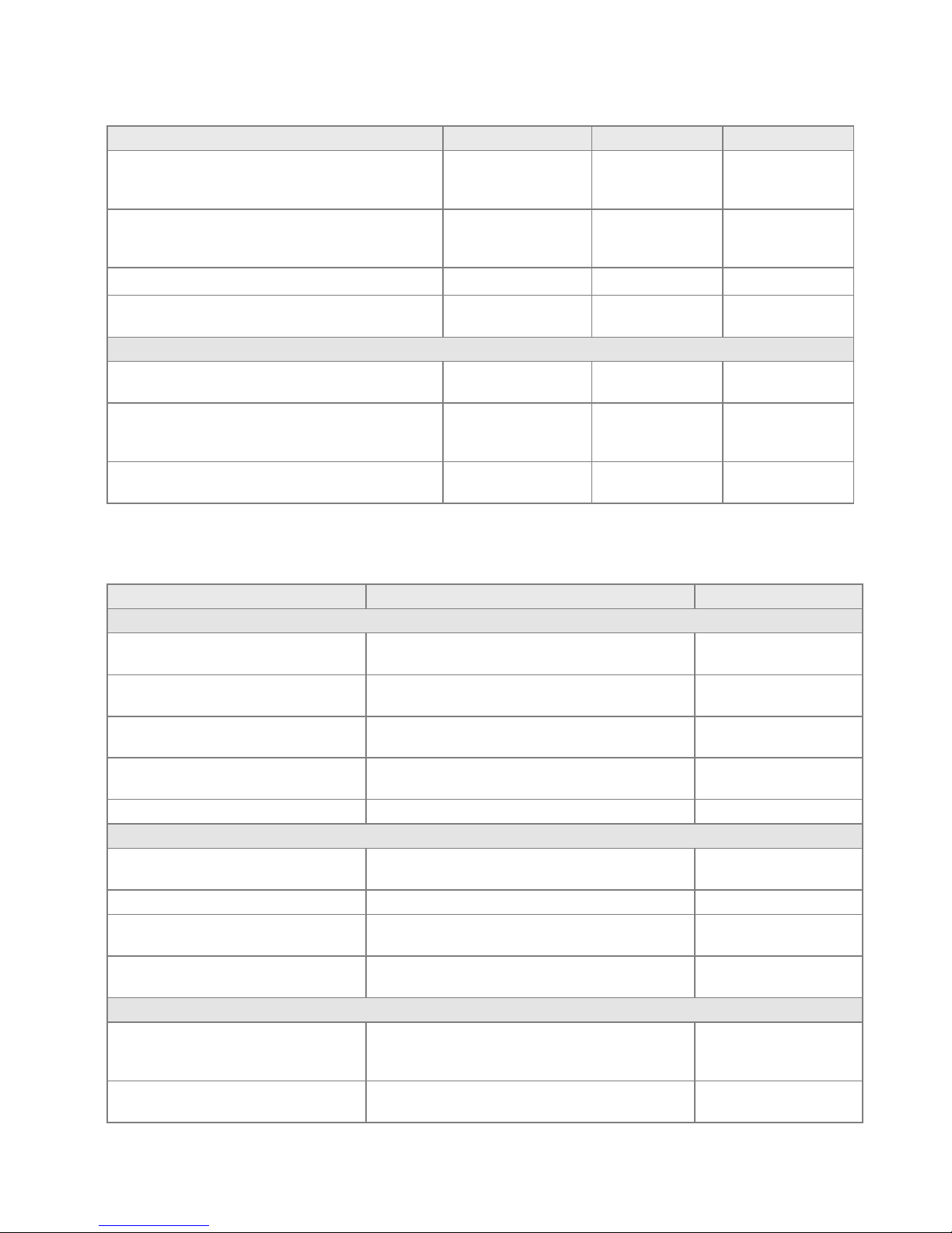
Remote Control Parameters
© 2016 Imagine Communications Corp. Proprietary and Confidential. Release 1.2.0 Revision A | Page 26
Page 27
IPA6800+
COMMAND PATH
DESCRIPTION
OPTIONS
DEFAULT
Configuration/Encapsulator_[1–2]/ASI FEC/Packets
Specifies the number of
FEC packets in each ASI
packet.
1–7 7 Configuration/Encapsulator_[1–2]/ASI FEC/RTP
Enables/disables the
encapsulator's Real
Time Protocol (RTP).
enable, disable
enable
Configuration/Decapsulator_[1–2]/ASI
Configuration/Decapsulator_[1–2]/ASI Pkt Len
ASI Packet length
setting
188, 204
188
Configuration/Decapsulator_[1–2]/Source
Configuration/Decapsulator_[1–2]/Source/Source IP
Source (normal or
IGMPv3)
0.0.0.0
IP
Configuration/Decapsulator_[1–2]/Source/Multicast
Group
Specifies the source IP
multicast group
address.
0.0.0.0
IP
Configuration/Decapsulator_[1–2]/Source/Port
Specifies the IP port
number.
0–65535
0
COMMAND PATH
DESCRIPTION
OPTIONS
STATUS/ETHERNET
Status/Ethernet/Link
Indicates the state of the Ethernet's physical
connection.
lost, negotiating, 10h,10f,
100h, 100f, 1000
Status/Ethernet/RX Pkts
Indicates the number of packets received in the last
second.
Counter
Status/Ethernet/TX Pkts
Indicates the number of packets transmitted in the last
second.
Counter
Status/Ethernet/RX Err Pkts
Indicates the number of errored packets received in the
last second.
Counter
Status/Ethernet/MAC Addr
Displays the Ethernet MAC address.
Mac address
Status/Encapsulator_[1–2]
Status/Encapsulator_[1–2]/LOS
Indicates if the encapsulator is experiencing a loss of
signal.
fault, noFault
Status/Encapsulator_[1–2]/Input
Indicates the type of encapsulator input.
ASI-188, ASI-204,
Status/Encapsulator_[1–2]/TX IP Rate
Indicates the encapsulator's transmit rate; in bits per
second (bps).
Counter
Status/Encapsulator_[1–2]/TX IP Pkts
Indicates the number of IP packets transmitted since
the last reboot or reset.
Counter
Status/Encapsulator_[1–2]/Dest [1–4]
Status/Encapsulator_[1–2]/Dest_[1–
4]/Status
status
working, unreachable,
noArp, ttlExceeded,
sourceQuench, unused
Status/Encapsulator_[1–2]/Dest_[1–4]/TX
Err Pkts
txErrPkts
Counter
Installation, Configuration, and Operation Manual Configuration and Status Parameters
Status Parameters
© 2016 Imagine Communications Corp. Proprietary and Confidential. Release 1.2.0 Revision A | Page 27
Page 28
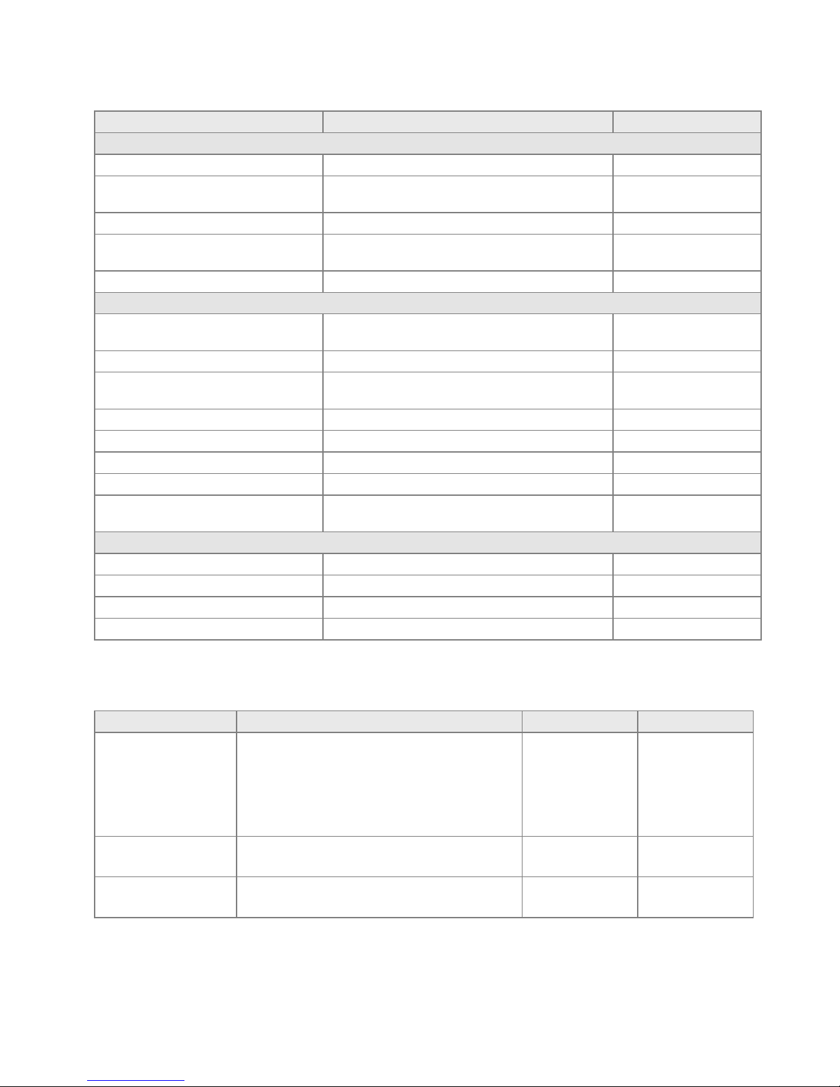
IPA6800+
COMMAND PATH
DESCRIPTION
OPTIONS
Status/Encapsulator_[1–2]/ASI
Status/Encapsulator_[1–2]/ASI/RX TS Rate
Received Transport Stream Rate
Counter
Status/Encapsulator_[1–2]/ASI/RX TS
Packets
Provides a count of trasnport stream packets received.
Counter
Status/Encapsulator_[1–2]/ASI/8b10bErr
Provides a count of 8b10b errors.
Counter
Status/Encapsulator_[1–2]/ASI/Sync Err
Provides a count of synchronization errors since the last
boot or power up.
Counter
Status/Encapsulator_[1–2]/ASI/TS Pres
Indicates whether or not a transport stream is present.
present, notPresent, n/a
Status/Decapsulator_[1–2]
Status/Decapsulator_[1–2]/Output
Indicate the packet size of the current, configured
output.
ASI-188, ASI-204, unknown
Status/Decapsulator_[1–2]/Uncorrectable
Provides a count of uncorrectable packets.
Counter
Status/Decapsulator_[1–2]/Corrected
Provides a count of the number of corrected packets in
the incoming transport stream.
Counter
Status/Decapsulator_[1–2]/TsRate
Indicates the current transport stream rate.
Rate
Status/Decapsulator_[1–2]/CBRLock
Indictaes the module has locked onto the ASI input.
Locked, NotLocked
Status/Decapsulator_[1–2]/FecPeriod
Indicates the FEC order setting.
Value
Status/Decapsulator_[1–2]/FecOrder
Indicates the FEC order setting.
Value
Status/Decapsulator_[1–2]/PktSize
Indicates the packet size of the incoming transport
stream packets.
Int
Status/SYS
Status/SYS/Software Version
Firmware revision number
#.#.#
Status/SYS/Hardware Version
Indicates the hardware revision number.
1 to 32
Status/SYS/Manufacturing Date
Indicates the module’s manufacturing date.
yyyy-mm-dd
Status/SYS/Serial Number
Indicates the module’s serial number.
String
COMMAND PATH
DESCRIPTION
OPTIONS
DEFAULT
Util/Clear
Clears and resets all status parameters.
Yes - This value is a momentary state. The module
accepts this value, clears all status values, and
returns this parameter to the ‘false’ state.
No - This value is the typical state for this
parameter.
Yes
No
No
Util/Load Defaults
Loads factory default settings and resets module.
Yes
No
No
Util/Reset
Resets the module.
Yes
No
No
Installation, Configuration, and Operation Manual Configuration and Status Parameters
Utility Commands
© 2016 Imagine Communications Corp. Proprietary and Confidential. Release 1.2.0 Revision A | Page 28
Page 29

IPA6800+
COMMAND PATH
DESCRIPTION
OPTIONS
Alarm/Eth/LOS
Indicates when Ethernet Link is lost.
Setting State: Enable, Disable
Status States: Active, Inactive
Priority: 1–10
On-Delay: 0–9999.9 (sec.)
Off-Delay: 0–9999.9 (sec.)
Ack: Yes, No
Alarm/ASI [1–2] Input LOS
Indicates an ASI Loss of Signal (LOS) when the respective
encapsulator’s LOS status parameter indicates a ‘Fault’ state.
Setting State: Enable, Disable
Status States: Active, Inactive
Priority: 1–10
On-Delay: 0–9999.9 (sec.)
Off-Delay: 0–9999.9 (sec.)
Ack: Yes, No
Alarm/ASI [1–2] Error
Indicates ‘Active’ when any of the following errors are
reported on the respective encapsulator: 8b10bErrors
increment A transport stream is not ‘Not Present’ The ASi
transmit rate falls to ‘0’.
Setting State: Enable, Disable
Status States: Active, Inactive
Priority: 1–10
On-Delay: 0–9999.9 (sec.)
Off-Delay: 0–9999.9 (sec.)
Ack: Yes, No
Alarm/Encap [1–2] Error
Indicates the Encapsulator is in use and is dropping IP
packets.
Setting State: Enable, Disable
Status States: Active, Inactive
Priority: 1–10
On-Delay: 0–9999.9 (sec.)
Off-Delay: 0–9999.9 (sec.)
Ack: Yes, No
Alarm/Decap [1–2] No
Input
Indicates the decapsulator’s transport stream rate has fallen
to zero.
Setting State: Enable, Disable
Status States: Active, Inactive
Priority: 1–10
On-Delay: 0–9999.9 (sec.)
Off-Delay: 0–9999.9 (sec.)
Ack: Yes, No
Alarm/Decap [1–2] Uncorr
Error
Indicates the decapsulator is experiencing uncorrectable
errors.
Setting State: Enable, Disable
Status States: Active, Inactive
Priority: 1–10
On-Delay: 0–9999.9 (sec.)
Off-Delay: 0–9999.9 (sec.)
Ack: Yes, No
Installation, Configuration, and Operation Manual Specifications
Alarm Commands
© 2016 Imagine Communications Corp. Proprietary and Confidential. Release 1.2.0 Revision A | Page 29
Page 30
IPA6800+
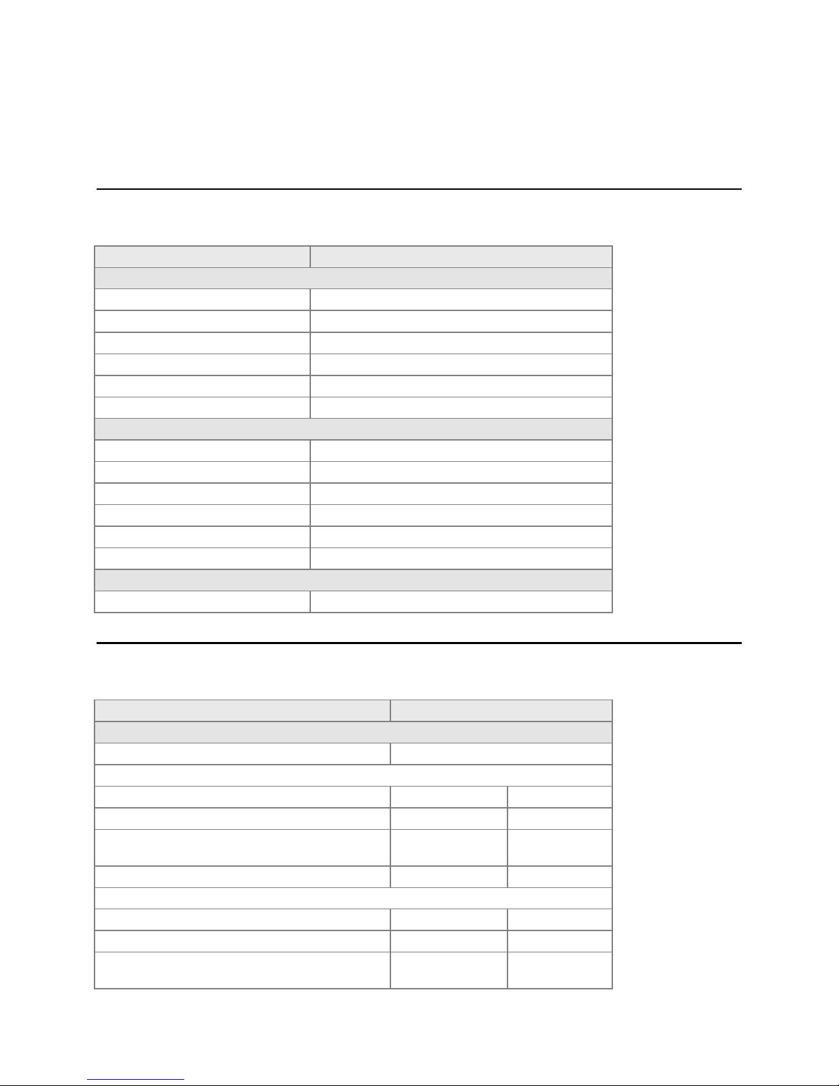
ITEM
SPECIFICATION
10/100/1000 BaseT Electrical Interface
Connector
RJ-45
Standard
IEEE 802.1
Differential Output Voltage
0.75 V ±0.83 dB
High Frequency Jitter (max)
0.3 ns
Clock Frequency
125 MHz ±0.01%
Common Mode Rejection
1V RMS 1–250 MHz
ASI Input/Output
Connector
BNC
Clock Rate
270 MHz ±100 ppm
Logic Levels
880 mV–200 mV p-p
Data Rate
0–210 Mbps in 100 bps Increments
Packet Size
188 or 204
Applicable Standards
DVB-ASI A011 Rev 1.0
Power Consumption
IPA6800+ Module
< 12 W
ITEM
SPECIFICATION
Supported in Frames
Imagine Communications Frame Models
6800+, 6802+
Front Module
Height – Fits 2RU 6800-series frames
7.7 cm.
3.0 in.
Depth – Including ejector handle
28.0 cm.
11 in.
Width – This module requires a two-slot-width Back
Connector
3.33 cm.
1.31 in.
Weight
0.13 kg.
0.28 lbs.
Back Connector
Height – Fits 2RU 6800-series frames.
7.7 cm.
3.0 in.
Depth – Excluding cable allowances
3.0 cm.
1.19 in.
Width – This connector requires two 6800-series frame
slots
3.33 cm.
1.31 in.
Installation, Configuration, and Operation Manual Specifications
Specifications
Electrical Specifications
Physical Specifications
© 2016 Imagine Communications Corp. Proprietary and Confidential. Release 1.2.0 Revision A | Page 30
Page 31
IPA6800+
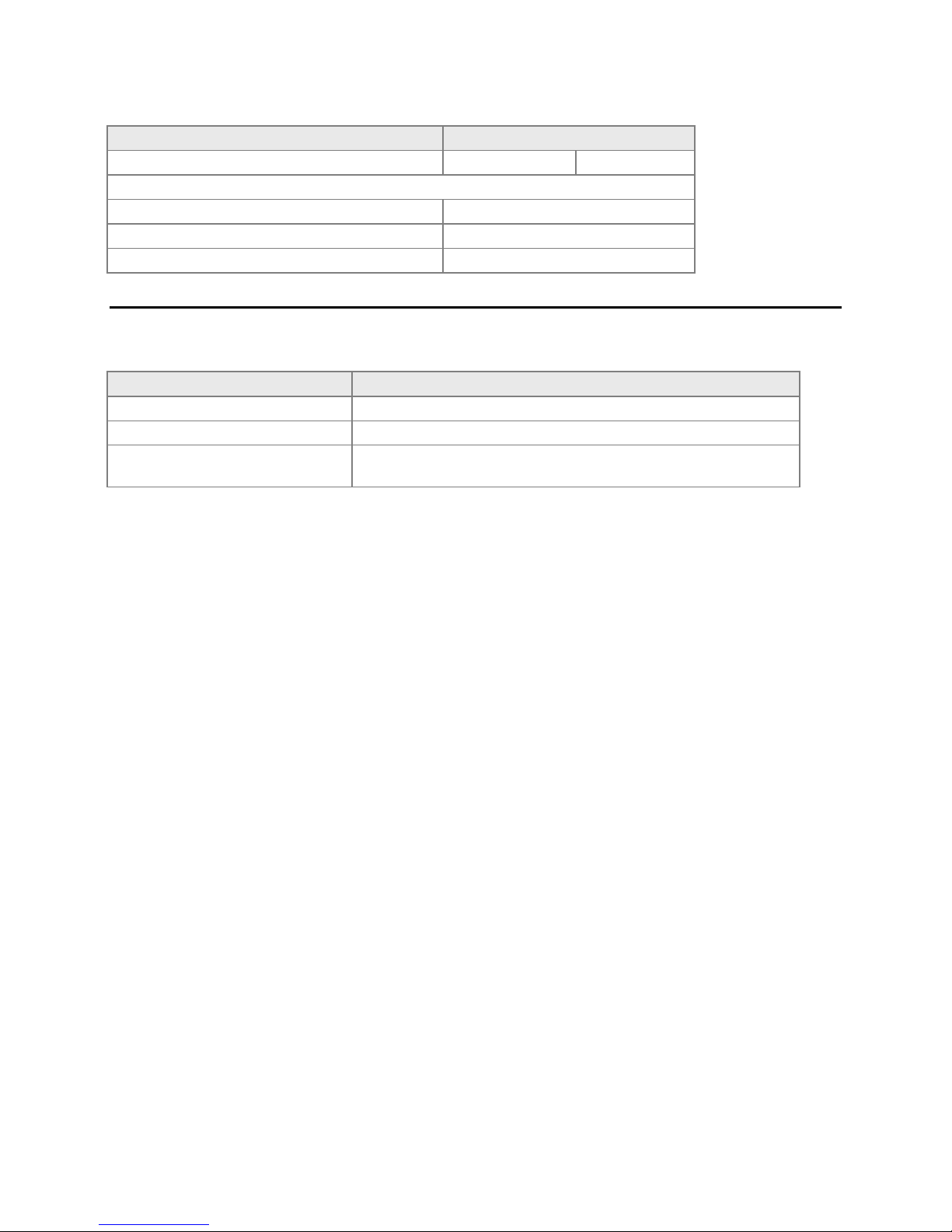
ITEM
SPECIFICATION
Weight
0.18 kg.
0.08 lbs.
Ambient Temperature
Operating Temperature Range
0–40° C (32–104° F)
Non-Operating Temperature Range
-40–65° C (-104–149° F)
Humidity
5–95% Non-Condensing
ITEM
SPECIFICATION
Safety Compliance (Pending approval)
UL 1419 & cUL (United States-UL1950 and Canada-CSA C22.2, No.1)
CE (Pending approval)
CE
EMC, FCC Certification (Pending
approval)
EMC: FCC Part 15 Class A and CISPR 22
Installation, Configuration, and Operation Manual Specifications
Regulatory Compliance
© 2016 Imagine Communications Corp. Proprietary and Confidential. Release 1.2.0 Revision A | Page 31
Page 32
IPA6800+ Appendix A
Appendix A
Installation, Configuration, and Operation Manual Software Communication Problems
Software Communication Problems
PROBLEM
The frame is powered up, but the module does not communicate with Magellan CCS Navigator or the
web GUI interface. Ensure you have specified the proper module slot.
SOLUTIONS
See your 6800+ Frame Installation and Operation Manual for more information about slot
identification.
Confirm there is an 6800+ ETH module installed in the frame.
Remove any legacy 6800 series product that is in the frame.
Magellan CCS software cannot communicate with legacy 6800 series products, even if these
modules may operate with card-edge controls in the frame. Legacy 6800 products do not have the
"+" symbol on their extractor handles.
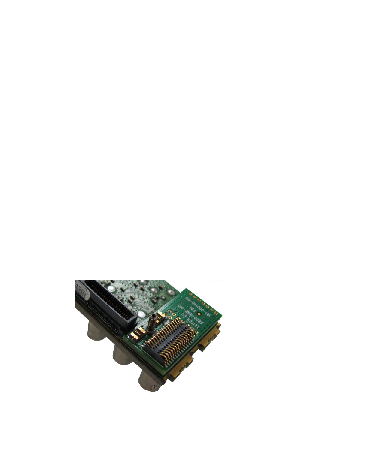
Check for pressed pins on the back module by following this procedure:
i. Unplug the front module.
ii. Unscrew and remove the back module.
iii. Inspect the 20- or 30-pin spring connector at the bottom of the back module, and verify that
the connector does not have any slightly bent or depressed pins.
iv. Carefully reposition any bent pins. If this is not possible, contact Imagine Communications
Customer Support.
Figure 1: Typical Back Module Spring Connector
PROBLEM
© 2016 Imagine Communications Corp. Proprietary and Confidential. Release 1.2.0 Revision A | Page 32
Page 33
IPA6800+ Appendix A
Installation, Configuration, and Operation Manual Software Communication Problems
The IP address of the frame has been forgotten.
SOLUTIONS
Follow this procedure:
1. Remove the ETH6800+ module from the frame.
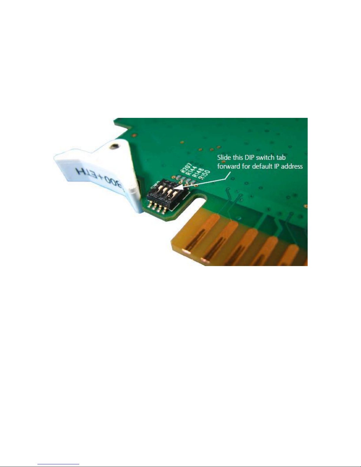
2. Select DIP switch 2 on the ETH6800+ module and slide the tab to the forward position.
This sets the ETH6800+ module to its default IP address of 192.168.100.250.
Figure 2: ETH6800+ DIP Switch
3. Use Magellan CCS Navigator or the web browser to interface with the ETH 6800+ module and then
set the desired IP address.
4. Set the DIP switch back to its normal position and then re-insert the module.
PROBLEM
There is no Ethernet connectivity to the frame.
SOLUTIONS
Verify that the correct IP address is being used. If your are not certain, refer to the above procedure
to set to default IP.
Verify that the ethernet cable is the correct type (a crossover cable is required for direct connection
from a PC).
Verify the Link and Activity (left and right) status LEDS are active on the RJ-45 connector at the rear
of the frame.
© 2016 Imagine Communications Corp. Proprietary and Confidential. Release 1.2.0 Revision A | Page 33
Page 34

IPA6800+ Appendix A
Installation, Configuration, and Operation Manual Hardware Communication Problems
Verify the Status LED is lit and green on the ETH6800+ card, as viewed from the front of the frame
with the door open.
Verify that the security settings on the PC allow for connection to a frame (TCP port 80 and UDP
ports 4000/4050 must be open).
Verify that the PC is configured for and can communicate on the desired subnet.
Verify that the frame reference signal has not been mistakenly plugged into the Communications
BNC connectors on the rear of the frame.
PROBLEM
Magellan CCS software sees the frame, but does not find all of the modules.
SOLUTIONS
Remove any legacy 6800 series products.
Plug your modules in before starting the discovery.
Start your discovery after the frame and all modules have fully powered up.
Refresh the Magellan CCS software and ensure that the installed modules are fully powered up first
before discovery.
PROBLEM
Magellan CCS Software does not respond after it is launched.
SOLUTION
Close any Magellan CCS software that is already launched.
PROBLEM
Magellan CCS software shows a module in the Control window, but cannot control it.
SOLUTION
Follow this procedure:
1. Set the module’s Local/Remote jumper to Remote.
2. Ensure the module name in the Control window matches the module type in the frame.
3. Gently push the module into its slot in the frame to ensure it is seated properly and powered up.
4. Verify that the Control window indicates the device is ready.
© 2016 Imagine Communications Corp. Proprietary and Confidential. Release 1.2.0 Revision A | Page 34
Page 35

IPA6800+ Appendix A
Installation, Configuration, and Operation Manual Hardware Communication Problems
Hardware Communication Problems
PROBLEM
After a power failure, the frames and PC do not communicate.
SOLUTIONS
Follow this procedure:
1. Wait four minutes for the frames to recover from the power failure.
2. Close the Magellan CCS software, and then restart the PC.
3. Restart the software application.
PROBLEM
The module does not seem to work.
SOLUTIONS
Ensure the correct frame is powered up.
Verify that all appropriate rear connections are secure.
Gently push the module into its slot in the frame to ensure it is seated properly. Then verify the
Status LED on the module is lit and green.
Ensure the back module does not have bent pins by following this procedure:
i. Unplug the front module.
ii. Unscrew and remove the back module.
iii. Carefully reposition any bent or depressed pins. If this is not possible, contact Customer
Support.
© 2016 Imagine Communications Corp. Proprietary and Confidential. Release 1.2.0 Revision A | Page 35
 Loading...