

HR Series Digital
Cameras
Operator Manual
May 2005
3800 Monroe Avenue
Pittsford, New York USA 14534
+1 585 264 0480
www.imaginant.com
techsupport@imaginant.com
Copyright (c) 2005. All Rights Reserved

Remove Power Cord from any HR series camera before replacing the fuses.
There are no user serviceable parts in the HR series cameras other than the fuse. The cameras should be
returned to the manufacturer for any repair.
Enlevez le cordon de secteur du HR avant de remplacer les fusibles.
Il n'y a pas d'utilisateur parties utilisables dans le HR, autrement que le fusible. Les appareils-photo de HR1100/200 devraient être retournés au fabricant pour n'importe quelle réparation.
Read the operator manual thoroughly and follow all safety related statements before operating the camera.
HR Series Digital Camera Operator Manual Page 2

TABLE OF CONTENTS
1. General Description............................................................................................4
2. Principles of Operation ......................................................................................5
3. Network Setup.....................................................................................................6
4. Installation...........................................................................................................8
5. Operation.............................................................................................................9
6. Camera Service.................................................................................................11
7. Appendix A: HR-1100c Specifications............................................................13
8. Appendix B: HR-200c Specifications..............................................................15
9. Appendix C: Trigger Input & Strobe Output Connections ............................17
HR Series Digital Camera Operator Manual Page 3

1. General Description
Description
HR series digital cameras are designed for high-quality image capture with fast shutter-speed,
action-stopping capabilities. These cameras produce photographic quality color images from
which high quality hardcopy prints can be created or upon which detailed image analysis may be
performed. These cameras offer in-camera image processing with JPEG compression. The HR
series cameras connect to a standard, high-speed Gigabit (1000Base-T) Ethernet network and use
the network interface for all configuration, setup and image-transfer operations. Application
software on the host Workstation provides camera system control.
International certification assures worldwide acceptance of the camera. The camera’s universal
internal power supply allows operation over all international supply voltages and frequencies.
The HR series cameras accept asynchronous trigger signals and can perform burst image captures
synchronized to these trigger signals. The user controls the number and the timing of the image
captures that the HR series cameras perform in response to an external trigger signal. The time
intervals between the trigger inputs and the moments of image capture are adjustable through the
HR series camera’s Ethernet Interface. The image capture timing for multiple HR series cameras
may be synchronized so as to simultaneously capture scenes from multiple angles, or to capture
scenes at higher effective frame rates.
The HR series cameras can generate strobe synchronization signals for controlling strobe lamps or
other equipment. The camera has six (6) X-sync strobe trigger outputs that may be flexibly
configured to control the firing sequence of up to six strobe lamps. The strobe lamp timing and
sequencing is adjustable by the user. The image capture timing of multiple HR series cameras can
be synchronized to enable multiple cameras to employ the same strobe illumination.
The HR-200C camera model can capture images as rapidly as 14 frames/second, up to the 15
image capacity of the camera’s internal memory. Subsequent images can be captured when
memory is freed through the transfer of images to the host Workstation. The average image capture
rate is determined by the image transfer rate to the host Workstation.
The HR series cameras accept standard EF-mount lenses and include an electrical interface for lens
focus and aperture control. Aperture control allows exposure adjustments beyond those achievable
using only the “electronic iris” integration-time control available in most industrial CCD cameras.
Aperture control allows the shutter-speed to remain constant over a wider range of ambient light
levels.
The primary differences between the HR series camera models are shown in the chart below. The
appendices provide detailed specifications for each HR series camera model.
Feature
Resolution 4032 x 2686 1608 x 1206
Aspect Ratio 3 x 2 4 x 3
Frame Rate (frames per sec) 2.5fps 14fps
Memory depth (#images) 4 15
Preview Resolution 672 x 448 804 x 606
HR-1100c HR-200c
HR Series Digital Camera Operator Manual Page 4

2. Principles of Operation
Camera Operation
The setup and configuration of the HR series cameras are controlled by application software
running on the Workstation. This software communicates with the camera through the Ethernet
Interface. Upon camera power-up, the camera attempts to link with the Workstation application
until a connection is attained. The camera then enters Setup Mode and begins the Setup Sequence
during which the Workstation configures the camera’s image capture timing parameters. After
configuration the camera is ready to capture images and to automatically transfer them to the
Workstation.
Images are transferred to the Workstation in either raw TIFF format or as fully processed color
images in compressed JPEG format. The JPEG format images may be compressed to a variety of
quality levels using the software interface. The user may thus adjust the quality level and,
consequently, the file size of the transferred image. The HR series cameras also support a Preview
Mode in which reduced resolution images are transferred to the host Workstation at a higher rate
for previewing. Preview images are 1 byte/pixel monochrome images, possess no TIFF header, and
are reduced in resolution both horizontally and vertically. The purpose of Preview Mode is to
continuously display monochrome images for focus, framing and exposure control.
The images captured by the HR series camera are each uniquely identified by an image sequence
number. This image sequence number is transmitted to the host Workstation together with each
image. The image sequence number is reset to zero at each power-up of the camera, and increments
by 1 with each image captured.
An Imaginant Camera Demonstration Application is provided. This is a demonstration Windows
application that provides control over the main set of HR series camera features. An HR Camera
Software Development Kit is provided for users that wish to write custom applications to take
advantage of the full set of HR series camera features. The HR Camera Software Development Kit
is easily integrated into user application software.
HR Series Digital Camera Operator Manual Page 5

3. Network Setup
Workstation
Any Workstation connected to an HR series camera must have a properly configured Ethernet
card. Workstations that run the Windows operating system must be configured to support the
TCP/IP protocol in the Windows software network setup function. HR series cameras are set to an
IP Address of “194.194.194.205” and the Workstation must be configured for IP Address
“194.194.194.206” with a subnet mask of “255.255.255.0” which will configure the interface for a
Class “C” network.
IP ADDRESS SUBNET MASK
Workstation 194.194.194.206 255.255.255.0
HR Camera 194.194.194.205 255.255.255.0
To optimize performance it is recommended that the camera and Workstation be the only devices
on the subnet network. This is because HR series cameras transfer a large amount of image data to
the Workstation following image capture and other network traffic will increase the image transfer
times. Although a dedicated camera to Workstation network is recommended, the camera protocol
and network activity should be compatible with standard Ethernet network configurations. Thus the
camera should successfully co-exist with other network activity although with potentially reduced
image transfer rates.
A Workstation connected to an HR series camera that is must also be connected to a network can
be configured with two (2) Ethernet cards. In this case, one Ethernet card can be dedicated to the
HR series camera while the other Ethernet card can service the network. In order to prevent any
routing problems, this second card should typically utilize a different IP Address Class, something
other than 194.194.194.X. Follow the Ethernet card manufacturer’s instructions in this regard.
Ethernet Cabling
Ethernet networks typically utilize a “hub” or “router” to connect multiple devices to the network.
In this configuration the hub performs a cabling translation by sending the Transmit signals from
one device to the Receive input of other devices and vice versa. Since the “hub’ performs this
translation, the cables that are employed with a hub are wired 1:1 (straight-through cables). This
means that the connectors at opposite ends of these cables have the same pins connected together
(pin 1 to pin 1, etc).
When a dedicated connection between an HR series camera and a Workstation is employed, a hub
is not used. In this case, a Crossover Cable would typically be necessary. A Crossover Cable is
wired so as to connect one device’s Transmit signals (output) to the Receive signal (input) of a
second device, and vice versa. However, the HR series camera will work with a straight-through
cable, as the cameras are capable of automatically swapping the Transmit and Receive signals as
necessary. This allows the HR series cameras to be connected directly to the Ethernet card of the
Workstation using either standard straight-through cables or using cables that have the Transmit
and Receive pairs swapped.
HR Series Digital Camera Operator Manual Page 6

Ethernet Indicator Lights
Two indicator lights are integrated into the Ethernet connector on the rear of the HR series camera.
The ACT/Link light is located in the lower right corner of the Ethernet connection socket and the
Link Speed light is located in the lower left corner of the Ethernet connection socket. These lamps
provide information about the status of the Ethernet connection.
When the HR series camera is connected to an Ethernet network, the lights indicate the following
Ethernet network conditions:
Indicator Light Indication Meaning
Green on The camera is connected.
ACT/Link Green flashing Data activity.
Off No link.
Off 10 Mbps
Link Speed Green 100 Mbps
Orange 1000 Mbps
HR Series Digital Camera Operator Manual Page 7

4. Installation
Camera Setup
1. Turn off the power and disconnect the power cord from the back of the camera.
2. Attach the EF-style lens to the front of the camera.
3. Mount the camera in the desired location using the standard camera tripod threaded holes.
- Camera is designed for indoor use only.
- Do not locate the camera in an explosive area.
- Do not allow chemicals to come into contact with the camera.
- Do not mount the camera on an unstable surface.
4. Connect an Ethernet cable between the camera and the Workstation.
5. Make connections to the camera’s trigger inputs and strobe outputs as desired (Appendix C).
6. Connect the supplied power cord to the back of the camera and plug it into an appropriate
supply with a properly grounded outlet.
WARNING - To reduce the risk of electric shock, connect the main power plug into a
properly grounded outlet only.
AVERTISSEMENT - pour réduire le risque de décharge électrique, reliez la prise de forces
seulement dans une sortie correctement au sol.
7. Turn on the camera power switch.
Software Setup
The Imaginant Camera Demo Application requires no special installation on the Workstation. The
application is described in more detail in the next section, and is also described in a separate user
manual.
The Imaginant Camera Demo Application uses the Winsock network services, which should be
available in the Windows installation. Please note: Any errors related to Winsock support must be
corrected by properly installing and configuring the Windows Operating System.
HR Series Digital Camera Operator Manual Page 8

5. Operation
General Operation
Once the Workstation and camera have been configured, connected, and powered on, the camera
will seek to communicate with a Workstation application like the Imaginant Camera Demonstration
Application. The order in which the camera is powered up and the application is started does not
matter as the application should wait indefinitely for the camera to connect, and the camera will
attempt to connect with the Workstation software indefinitely. For convenience, it is assumed in
this manual that the camera is powered on before the Imaginant Camera Demo Application is
started, although this is not necessary. Note that the Imaginant Camera Demo Application is
capable of reconnecting to the camera if the camera power is cycled while the Imaginant Camera
Demo Application is running.
Imaginant Camera Demonstration Application
The Imaginant Camera Demonstration Application, “HRDemoApp”, can be used to control HR
series cameras and to acquire images from the cameras, saving the images as JPEG files. Refer to
the documentation for the HR Demo Application for complete installation and operation
instructions.
Preview Mode
The Imaginant Camera Demo Application offers a Preview feature for viewing images from the
camera during camera setup. The displayed images are updated about once per second or faster
depending on the HR series camera model. This allows the operator to rapidly frame, zoom, focus
and adjust the camera. Selecting the “Preview” button (“P”) in the Demo Application enables the
Preview Mode after which an image display window should appear on the desktop. The camera
will be put into Preview Mode and images will be automatically and continuously captured, read
out of the camera, and displayed in the image display window on the Workstation. Preview Mode
must be turned off prior to capturing still images from the camera.
Camera Operation
The status lights on the RJ-45 Ethernet connector of the camera indicate Ethernet connection status
and activity as well as reflect camera boot activity following the application of power to the
camera. Upon power-up, the HR series camera must perform several boot tasks before the
connection with the Workstation can be established. These tasks and the related status lights
conditions are listed below:
1. On power-up, the LEDs on the RJ-45 connector should illuminate within about 6 seconds.
2. If the camera is properly cabled to a network card in the Workstation the “LINK” LED should
illuminate when auto-negotiation is completed.
HR Series Digital Camera Operator Manual Page 9

3. The “Activity” lights should flash briefly about 3 seconds after the “LINK” LED is lit and
should continue to flash until a connection with the Imaginant Camera Demonstration
application is achieved.
4. The Imaginant Camera Demonstration Application will normally begin communicating with
the camera while the “Available Camera List” dialog box is open.
5. At this point the camera has powered-up correctly and is attempting to connect to the
application on the Workstation.
6. The “Activity” lights will stop flashing when the camera has linked with the Imaginant Camera
Demonstration application. This indicates the camera is connected and configured for
communication with the Imaginant Camera Demonstration application.
Imaginant Camera Software Development Kit
A Software Development Kit (SDK) is available from Imaginant at no charge. The SDK allows a
system developer to easily integrate the HR series cameras into other software applications.
HR Series Digital Camera Operator Manual Page 10

6. Camera Service
Serviceable Parts
There are no user serviceable parts in the cameras. Cameras must be returned to the manufacturer
for repair.
Power Cord Requirements
The camera is supplied with a power cord suitable for North American use that meets all
applicable safety requirements. Contact Imaginant for replacement power cords for North
American use.
WARNING: Use of the wrong power cord may result in a hazardous condition.
Use the proper cord in compliance with local laws when connecting any Imaginant HR series
camera to any 240 VAC supply network.
Power Cords for international applications must meet the safety requirements in the country of use.
To maintain the safety certification standards, any power cord used with an HR series camera must
meet the minimum specifications listed below.
The power cord must be:
o Flexible
o 3 conductor
o 0.75mm2 area conductors
o Less than 4.5m long
o Suitable for indoor use
o Have insulation rated to 60 deg C
o Have an IEC320, sheet C13 type female connector to mate to the camera.
The cord and the plug:
o Must be adequately rated for the voltage and the current
o Must have a protective ground connection
o Must have safety certification based on the applicable EN standard(s)
o Should be compatible with the local receptacle
HR Series Digital Camera Operator Manual Page 11
Fusing
“CAUTION: Double Pole/Neutral Fusing”. Both +AC and Neutral power supply lines are fused.
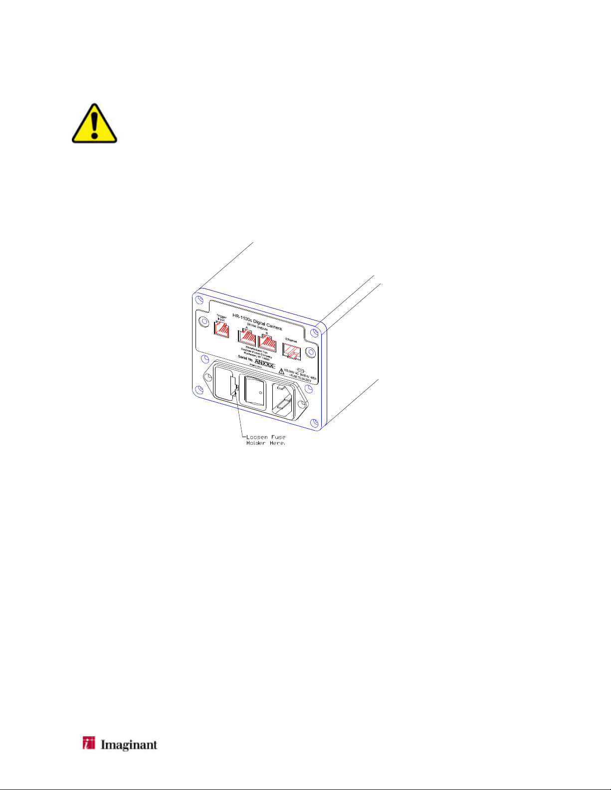
Fuse Replacement
1. Turn off the camera power switch and remove the power cord from the back of the camera.
2. Using a small screwdriver, gently unlatch the fuse holder door from the power inlet module on
the back of the camera.
3. Replace the fuses using only the type specified on the nameplate of the camera.
4. Re-install the fuse holder in the original orientation and press it in gently until it latches.
5. Re-connect the power cord and turn on the power to the camera.
HR Series Digital Camera Operator Manual Page 12

7. Appendix A: HR-1100c Specifications
CCD Summary
Image sensor Kodak KAI-11000 interline transfer progressive scan CCD.
Resolution 4032 (H) x 2686 (V)
Pixel size 9µm x 9µm
Aspect ratio 3:2
CCD sensor diagonal Full 35mm format (43mm diagonal)
In-Camera Image Processing
File format supported JPEG, TIFF
JPEG Quantization tables Default and user downloadable.
JPEG compression 100 programmable levels.
White point Automatic and user adjustable white balance.
Color correction Default and user programmable color correction matrix.
Color reproduction Default matrix configured for sRGB color space.
Tone correction Default and user programmable tone correction for sRGB.
System Summary
Shutter speed (Integration time) 1/10,000 sec. – ½ sec. Adjustable in 1/10,000 second increments.
ISO 50 – 800, adjustable in <1/3-stop increments.
Bits/Pixel 12 (captured before processing)
Dynamic range 60 dB minimum (peak signal to RMS noise @ 25°C, ISO 100)
Lens control (focus and aperture) Supports 35mm format electronically controlled EF mount lenses.
Preview mode 1 fps monochrome 672 x 448, continuous readout mode for framing,
set-up and adjustment.
Maximum burst capture rate 2.5 images per second.
Sustained capture rate 1 image every 3.5 seconds.
Image storage 4 images maximum
Triggering Programmable delays from internal and external trigger sources.
Exposure Control
User selectable modes Manual or automatic
Manual exposure mode
configurable parameters:
Interface Specification
Network connectivity 1000Base-T (Gigabit), 100Base-T or 10Base-T Ethernet interface.
Trigger inputs Two (2) external trigger inputs, 5-volt logic.
Timing adjustments Adjustable trigger-to-capture delays from 100 µseconds to 4.8
Strobe outputs Six (6) contact closure strobe triggers. Strobe outputs are
Integration time (shutter speed)
ISO (sensitivity)
Lens aperture
Flash on, Flash off
seconds.
programmable in any desired triggering sequence.
Strobe advance Programmable X-sync timing to compensate for variable strobe
delays.
HR Series Digital Camera Operator Manual Page 13

System Requirements
Host OS support Compatible with Windows 2000, XP.
Ethernet Host computer with built-in Ethernet interface or additional card.
Camera Firmware Field upgradeable through Ethernet interface.
Physical Specifications (without
lens)
Weight 2.2 kg (4.75 lbs)
Physical dimensions 225.6mm (8.88”) L x 97mm (3.82”) H x 104.5mm (4.11”) W
Lens mount Electrical and mechanical EF mounts. (Accepts 35mm SLR lenses.)
Tripod mounts Two (2) standard ¼”- 20 threads/inch
Trade-dress Silver front and rear plates, white center enclosure.
Power Specifications
Power connector International (IEC 320) AC power input connector.
AC voltage range 100 - 240 VAC
Frequency range 50 - 60 Hz
Power Rating 40 VA (maximum)
Power Consumption (RMS) 15 Watts (maximum)
Environmental Specifications
Operating temperature -10° to 60°C (14°to 140°F) non-condensing.
Storage temperatures -40° to 70°C (-40° to 158°F) non-condensing.
Relative humidity < 95% at all times
Acceleration and shock
Regulatory Compliance
3.5g (rms), 5-150Hz sinusoidal vibration or shock ? 20g.
CSA, CE and FCC Part 15, Class A.
HR Series Digital Camera Operator Manual Page 14

8. Appendix B: HR-200c Specifications
CCD Summary
Image sensor Kodak KAI-2000 interline transfer progressive scan CCD.
Resolution 1608 (H) x 1206 (V)
Pixel size 7.4µm x 7.4µm
Aspect ratio 4:3
CCD sensor diagonal 14.8mm
In-Camera Image Processing
File format supported JPEG, TIFF
JPEG Quantization tables Default and user downloadable.
JPEG compression 100 programmable levels.
White point Automatic and user adjustable white balance.
Color correction Default and user programmable color correction matrix.
Color reproduction Default matrix configured for sRGB color space.
Tone correction Default and user programmable tone correction for sRGB.
System Summary
Shutter speed (Integration time) 1/10,000 sec. – ½ sec. Adjustable in 1/10,000 second increments.
ISO 125 – 800, adjustable in 1/3-stop increments.
Bits/Pixel 12 (captured before processing)
Dynamic range 60 dB minimum (peak signal to RMS noise @ 25°C, ISO 100)
Lens control (focus and aperture) Supports 35mm format electronically controlled EF mount lenses.
Preview mode 1 fps monochrome 804 x 606, continuous readout mode for framing,
set-up and adjustment.
Maximum burst capture rate 14 images per second.
Sustained capture rate 1 image every 1.2 seconds.
Image storage 15 images maximum
Triggering Programmable delays from internal and external trigger sources.
Exposure Control
User selectable modes Manual or automatic
Manual exposure mode
configurable parameters:
Interface Specification
Network connectivity 1000Base-T (Gigabit), 100Base-T or 10Base-T Ethernet interface.
Trigger inputs Two (2) external trigger inputs, 5-volt logic.
Timing adjustments Adjustable trigger-to-capture delays from 100 µseconds to 4.8
Strobe outputs Six (6) contact closure strobe triggers. Strobe outputs are
Integration time (shutter speed)
ISO (sensitivity)
Lens aperture
Flash on, Flash off
seconds.
programmable in any desired triggering sequence.
Strobe advance Programmable X-sync timing to compensate for variable strobe
delays.
HR Series Digital Camera Operator Manual Page 15

System Requirements
Host OS support Compatible with Windows NT, 2000, XP.
Ethernet Host computer with built-in Ethernet interface or additional card.
Camera Firmware Field upgradeable through Ethernet interface.
Physical Specifications (without
lens)
Weight 2.2 kg (4.75 lbs)
Physical dimensions 225.6mm (8.88”) L x 97mm (3.82”) H x 104.5mm (4.11”) W
Lens mount Electrical and mechanical EF mounts. (Accepts 35mm SLR lenses.)
Tripod mounts Two (2) standard ¼”- 20 threads/inch
Trade-dress Silver front and rear plates, white center enclosure.
Power Specifications
Power connector International (IEC 320) AC power input connector.
AC voltage range 100 - 240 VAC
Frequency range 50 - 60 Hz
Power Rating 40 VA (maximum)
Power Consumption (RMS) 15 Watts (maximum)
Environmental Specifications
Operating temperature -10° to 60°C (14°to 140°F) non-condensing.
Storage temperatures -40° to 70°C (-40° to 158°F) non-condensing.
Relative humidity < 95% at all times
Acceleration and shock
3.5g (rms), 5-150Hz sinusoidal vibration or shock ? 20g.
Regulatory Compliance
CSA, CE and FCC Part 15, Class A.
HR Series Digital Camera Operator Manual Page 16

9. Appendix C: Trigger Input & Strobe Output Connections
Pin # Trigger Input Strobe Output A Strobe Output B
1 Trig 0 – Image 0 Trigger Signal Strobe 0 – Fire Strobe 0 Strobe 3 – Fire Strobe 3
2 Return Return Return
3 Trig 1 – Image 1 Trigger Signal Strobe 1 – Fire Strobe 1 Strobe 4 – Fire Strobe 4
4 Return Return Return
5 No Connection Strobe 2 – Fire Strobe 2 Strobe 5 – Fire Strobe 5
6 Return Return Return
7 Not Applicable No Connection No Connection
8 Not Applicable Return Return
9 Not Applicable No Connection No Connection
10 Not Applicable No Connection No Connection
Assemblies for both the Trigger Cable and Strobe Cable are available from Imaginant. Please contact us
via e-mail at imaginantinfo@imaginant.com to purchase these assemblies.
Trigger
Input
Pin 1 = Trig 0
Pin 2 = Return
Pin 3 = Trig 1
Pin 6 = Return
Pin 5 = N/C
Pin 4 = Return
Strobe Outputs
A B
Pin 1 = Stobe 0
Pin 2 = Return
Pin 3 = Strobe 1
Pin 4 = Return
Pin 5 = Strobe 2
Pin 7 = N/C Pin 7 = N/C
Pin 6 = Return Pin 6 = Return
Pin 10 = N/C Pin 10 = N/C
Pin 9 = N/C Pin 9 = N/C
Pin 8 = Return
The Trigger Input accepts 6-position category 3 modular plugs and each Strobe Output accepts 10-position
category 3 modular plugs.
Pin 1 = Stobe 3
Pin 2 = Return
Pin 3 = Strobe 4
Pin 8 = Return
Pin 4 = Return
Pin 5 = Strobe 5
HR Series Digital Camera Operator Manual Page 17
 Loading...