

Page 1

4 Channel Mobile
Digital Video Recorder
Installation Manual
※ The picture, diagram and function might differ according to the specifications.
©1999-2004
Contents of this user manual are protected under copyrights and computer program laws.
First Edition April 7, 2005
Thank You
Before operating the system, please read this User’s Manual thoroughly and retain it for future reference.
Page 2

Mobile DVR - Installation Manual
2/47
WARNING
TO REDUCE FIRE OR SHOCK HAZARD, DO NOT EXPOSE THE
UNIT TO RAIN OR MOISTURE.
This installation should be made by a qualified service person and should confo rm to all local codes.
Page 3
Mobile DVR - Installation Manual
3/47
Important Safeguards and Cautions
Signs of Caution and Warning:
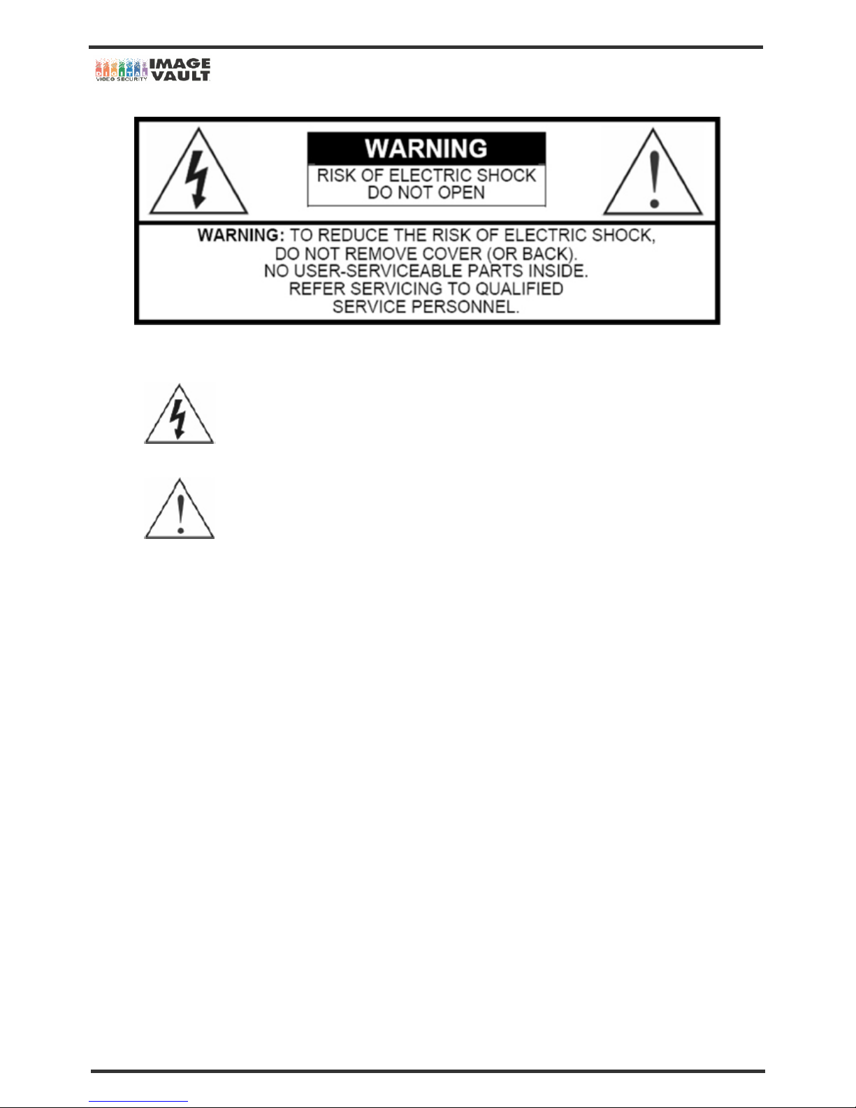
The lightning flash with arrowhead symbol, within an equilateral triangle, is intended to alert the user to
the presence of not insulated “dangerous voltage” within the product’s enclosure that may be of
sufficient magnitude to constitute a risk of electric shock. This sign indicates that the user could die of
wounded seriously if not used or installed properly.
The exclamation point within an equilateral triangle is intended to alert the user to the presence of
important operating and maintenance (servicing) instructions in the literature accompanying the
appliance. This sign indicates that the user could be wounded or could expert property damage if not
used or installed properly.
The information in this manual is believed to be accurate as of the date of publication. Our company is not responsible for any problems resulting
from the use thereof. The information contained herein is subject to change without notice. Revisions or new editions to this publication may be
issued to incorporate such changes.
THIS INSTALLATION SHOULD BE MADE BY A QUALIFIED SERVICE PERSON AND SHOULD CONFIRM TO ALL LOCAL
CODES.
Page 4

Mobile DVR - Installation Manual
4/47
Important Safeguards
Must follow these details to prevent material damage beforehand.
Electric Safety
Warning
To reduce a risk of fire or electrical shock. Do not expose this product to rain or moisture.
Caution about lithium battery
Warning
1. Change the battery after turning the power off of the DVR.
2. Connect the polarity of the lithium properly while changing.
3. Change with the same type of battery recommended by the DVR manufacturer.
4. Follow the instruction from battery manufacturer to change the battery.
Safeguards
Warning
1. Use the adaptor, which is supplied or recommended by the supplier. It may cause fire.
2. Do not dismantle or assemble the product. It may cause malfunction or fire.
3. Do not touch the product with wet hands. It may cause malfunction or fire.
4. Matters must be ensured to a professional for installation. It may cause malfunction, electric shock or fire.
5. Consult the place of purchase if the need for installation arises. Delinquent installation may be the reason for malfunction, electric shock
or fire.
6. Ground applies to video products equipped with a 3-wire grounding type plug having a third (grounding) pin. This plug only fits into a
grounding-type power outlet. If grounding is not done, it may cause malfunction or electric shock.
7. Ground connection must not touch gas pipe, water pipe or telephone line. If grounding is not done properly, it may cause electric shock.
8. Prevent metallic foreign substance inside the product. It may cause malfunction or electric shock.
9. Do not spray insecticide or flammable spray while driving. It may cause fire.
10. Prevent water from entering inside electrical parts. Clean with a dry towel or malfunction or electric shock could result.
Caution
1. Use the power cord, which is supplied or recommended by the supplier. The internal fan rotates at high speed and may cause an
accident.
2. Do not drop, give strong vibration, or shock to the product. It may cause malfunction.
3. The air inhaler on each sides and the fan of the back panel must not be blocked during installation. The internal temperature of the
product would be greater than allowable and could cause malfunction or fire.
4. Do not touch the product or the power cord when there is thunder. It may cause electric shock.
5. Do not install the product near or on top of heating source. The internal temperature would be greater than allowable and could cause
malfunction or fire.
6. Do not install the product on inclined or unstable location or where vibration could be committed. It may cause malfunction.
Page 5

Mobile DVR - Installation Manual
5/47
Caution about the Power
Warning
1. Must use the outlet of the grounding to connect the power cord. It may cause fire.
2. Do not connect on the middle of power cord or use extension cord. It may generate heat or cause fire.
3. Do not touch the power cord with wet hands. It may cause electric shock.
4. Keep power cord dry and protect from humidity. It may generate heat or cause fire. The power cord is not waterproof.
5. Hold the body of the plug while removing the power plug. Do not pull the power cord. Damage to the power cord may generate heat or
cause fire.
6. Check the power plug regularly. Humidity and moderation in smoking may cause fire.
7. Remove power cord from outlet when product is not used for a long time. It may cause a short-circuit or electric shock.
Warning
1. Do not turn off the power by removal of the power plug. To turn off the power, click the power button from the back panel.
2. Do not cut off the power artificially, or give shock or vibration to unit while the hard disk is activating. It may cause hard disk failure or loss
of data.
Page 6

Mobile DVR - Installation Manual
6/47
CONTENTS:
IMPORTANT SAFEGUARDS AND CAUTIONS 3
SIGNS OF CAUTION AND WARNING: 3
IMPORTANT SAFEGUARDS 4
1. SYSTEM STRUCTURE 8
1.1 CHECK THE CONTENTS OF THE BOX 8
2. SYSTEM CONFIGURATION 9
2.1 FRONT PANEL 9
2.2 REAR PANEL 11
3. INSTALLATION 12
3.1 CONNECTING PERIPHERAL DEVICES 12
3.1.1 CAMERA INPUT 13
3.1.2 MONITOR OUT 13
3.1.3 SVHS OUTPUT 13
3.1.4 SERIAL PORT 13
3.1.5 ETHERNET 10/100 13
3.1.6 ALARM & RELAY 13
3.1.7 AUDIO INPUT AND OUTPUT 14
3.1.8 POWER INPUT (USING AS NORMAL DVR) 14
3.1.9 POWER INPUT (USING AS MOBILE DVR) 14
3.1.10 DIRECTION KEY BUTTON 15
3.1.11 PORTABLE CONTROLLER 16
3.1.12 SWITCHING NTSC OR PAL 17
3.2 SYSTEM STARTUP AND SHUTDOWN 18
3.2.1 SYSTEM STARTUP 18
3.2.2 SYSTEM SHUTDOWN 18
3.2.3 COUNTERMEASURES AFTER ABNORMAL SHUTDOWN 18
3.2.4 HEART BEAT FUNCTION 19
Page 7

Mobile DVR - Installation Manual
7/47
4. REMOVABLE HDD INSTALLATION 20
4.1 INSTALLING NEW HDD 20
4.1.1 INSTALLING ORDER 20
4.2 REPLACING HDD 21
5. DVR READER INSTALLATION & EXTERNAL HDD DEVICE INSTALLATION 23
5.1 INSTALLING SOFTW ARE 23
5.2 INSTALLING EXTERNAL HDD DEVICE 24
5.2.1 USING HARD RACK FRAME 24
5.2.2 INSTALLING IEEE-1394 CARD 27
5.2.3 INSTALLING EXTERNAL HDD RACK CASE 29
5.2.4 INSTALLING USB 2.0 EXTERNAL HDD DRIVE 31
5.2.5 INSTALLING USB 2.0 EXTERNAL HDD DRIVE WITH EZUSB 33
6. NETWORK SETUP 35
6.1 WHAT IS DDNS? 35
6.2 DDNS SIGN UP 36
6.2.1 IPUPDATER SIGN UP 36
6.2.2 DNIP SIGN UP 38
6.2.3 NAMEIP SIGN UP 41
6.3 DVR NETWORK SETUP 43
6.3.1 INFORMATION ON IP SETTING 44
6.4 IP SHARING ROUTER SETUP 45
6.5 DVR MANAGER SETUP 46
7. FAQ 47
Page 8
Mobile DVR - Installation Manual
8/47
1. SYSTEM STRUCTURE
1.1 Check the contents of the box
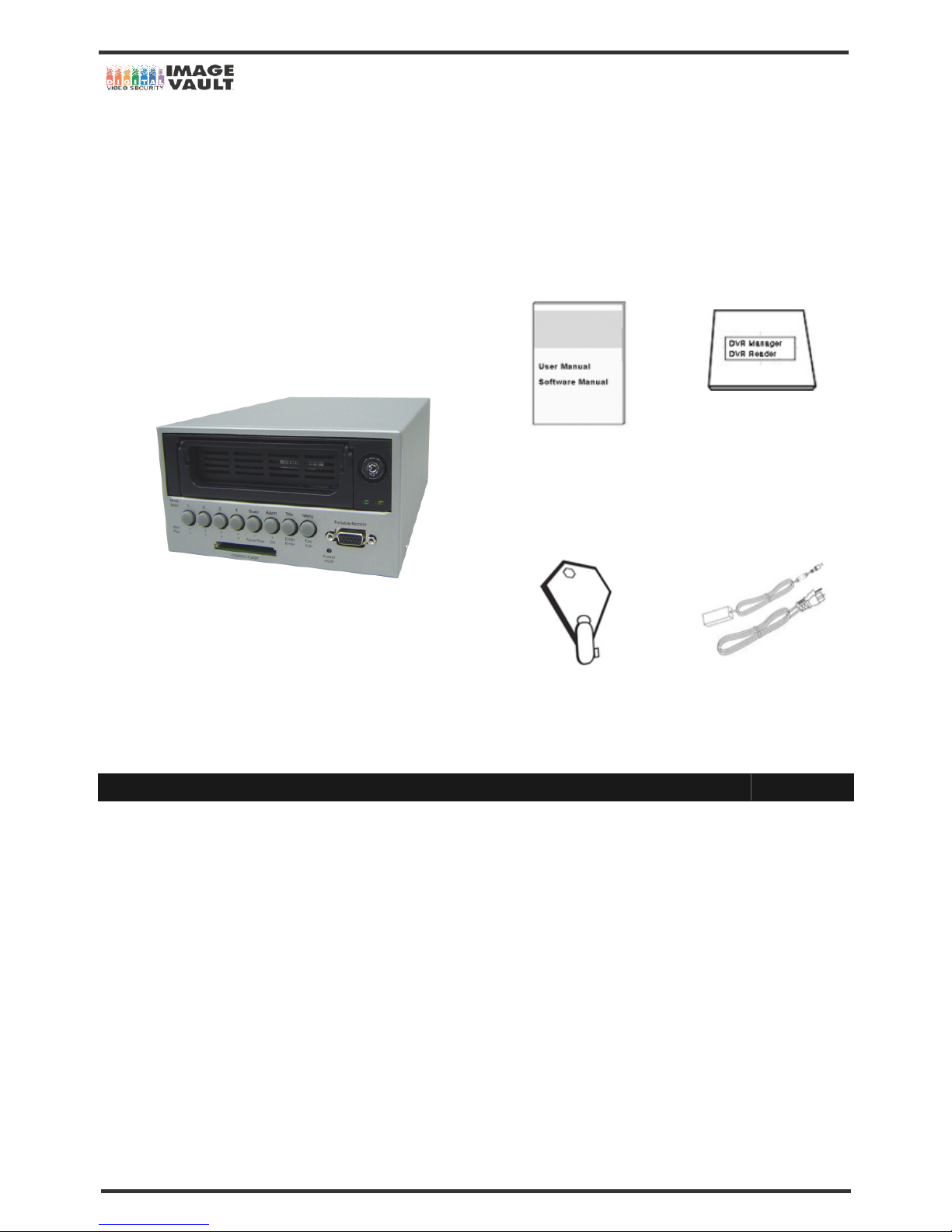
The following items are supplied with 4Ch 120 FPS digital video recorder. If any of these items is missing or damaged, notify your dealer or
installer immediately. Keep the packing utilities for moving or storage purposes afterwards.
Manual
Software CD
(DVR Reader, DVR Manager)
DVR
Key
DC 24V Adaptor & Plug
Model No. Model Name & Description Qty.
- 4 Channel 120 FPS Digital Video Recorder Unit 1
DCP-24V DC24V Adaptor (Power supply adaptor, DC 24V, 1.5 Amps) 1
RCK-1K Hard Rack Key (Key to open and close the HDD rack.) 1
- Manual (User’s Manual) 1
- DVR Manager (Remote Viewing Program)
- DVR Reader (HDD Reading Program)
1
Page 9
Mobile DVR - Installation Manual
9/47
2. SYSTEM CONFIGURATION
2.1 Front Panel
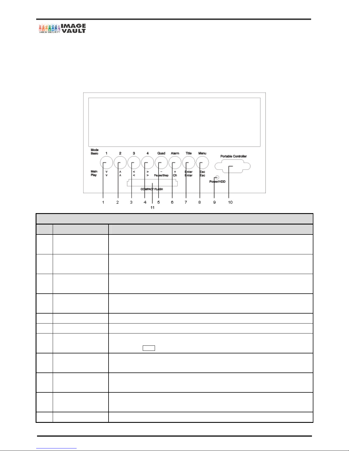
The buttons on both the front panel of the DVR have different functions for three different modes; Basic Mode for displaying the screen, Main
Mode for setting the configurations and Play Mode for replaying. Each buttons can activate different functions.
BASIC MODE (when the DVR is in previewing the images)
No. Buttons Functions
1 Camera 1 select
Press this button to view full image from camera 1.
The image from camera 1 will be paused if you press the button again.
2 Camera 2 select
Press this button to view full image from camera 2.
The image from camera 2 will be paused if you press the button again.
3 Camera 3 select
Press this button to view full image from camera 3.
The image from camera 3 will be paused if you press the button again.
4 Camera 4 select
Press this button to view full image from camera 4.
The image from camera 4 will be paused if you press the button again.
5 Quad screen select Press this button to view all four pictures (Quad) on one display screen
6 Alarm on/off switch Press this button to turn ON and OFF the alarm
7
OSD (On Screen Display)
on/off switch
OSD will initially be displayed on the screen. When the [OSD] button is clicked once, the OSD will
disappear. Click TITLE button again and the text will reappear.
8 Menu button
Press this button to display the Menu setup. Set the environment of the DVR according to the user
requirement.
9 Power/HDD LED
The ‘Power’ light indicates that the power is being supplied to the unit. (Red: Working). And the ‘HDD’
light indicates when the camera image is being stored into or retrieved from the HDD (Hard Disk Drive).
10
Portable Controller
Connector (OPTION)
A connector for Portable Controller.
11 CompactFlash Slot Insert Compact Flash Card for CF backup.
Page 10
Mobile DVR - Installation Manual
10/47
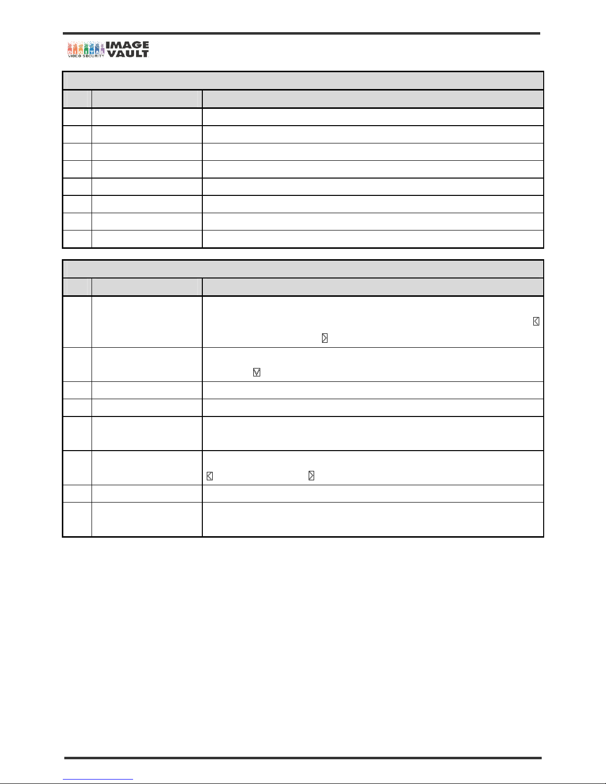
MENU MODE (when the user enters into main menu of DVR)
No. Buttons Functions
1 Downward direction Press this button to move the cursor down.
2 Upward direction Press this button to move the cursor up.
3 Left direction Press this button to move the cursor to the left.
4 Right direction Press this button to move the cursor to the right.
5 Downward value Press this button to change numbers, letters or value (Downward).
6 Upward value Press this button to change numbers, letters or value (Upward).
7 Enter button Press this button to enter to the next menu.
8 Escape button Press this button to return to the previous menu.
PLAY MODE (when the DVR is in playback mode)
No. Buttons Functions
1 Reduce play speed
Press this button again and again to decrease the play speed when the speed is higher than normal
speed. When it is normal play speed, press this button to pause the screen. To play again, press
button for backward playback and button for forward playback.
2 Increase play speed
Press the button again and again to increase the play speed to a maximum (x8192). To lower the
speed, press
button.
3 Reverse playback Press this button to start backward playback of recording.
4 Playback Press this button to start forward playback of recording.
5
Pause/
Play frame by frame
Press this button to pause the picture. Press again and again to play frame by frame.
6 Channel selection
Press this button to convert and do pause each channel during play back. To restart playing, press
for backward playback and for forward playback.
7 Enter button Press this button to enter to the next menu.
8 Escape button
Press this button to return to the previous menu. Use to cancel the password just typed at the setting
menu or to return to previous menu.
Page 11
Mobile DVR - Installation Manual
11/47
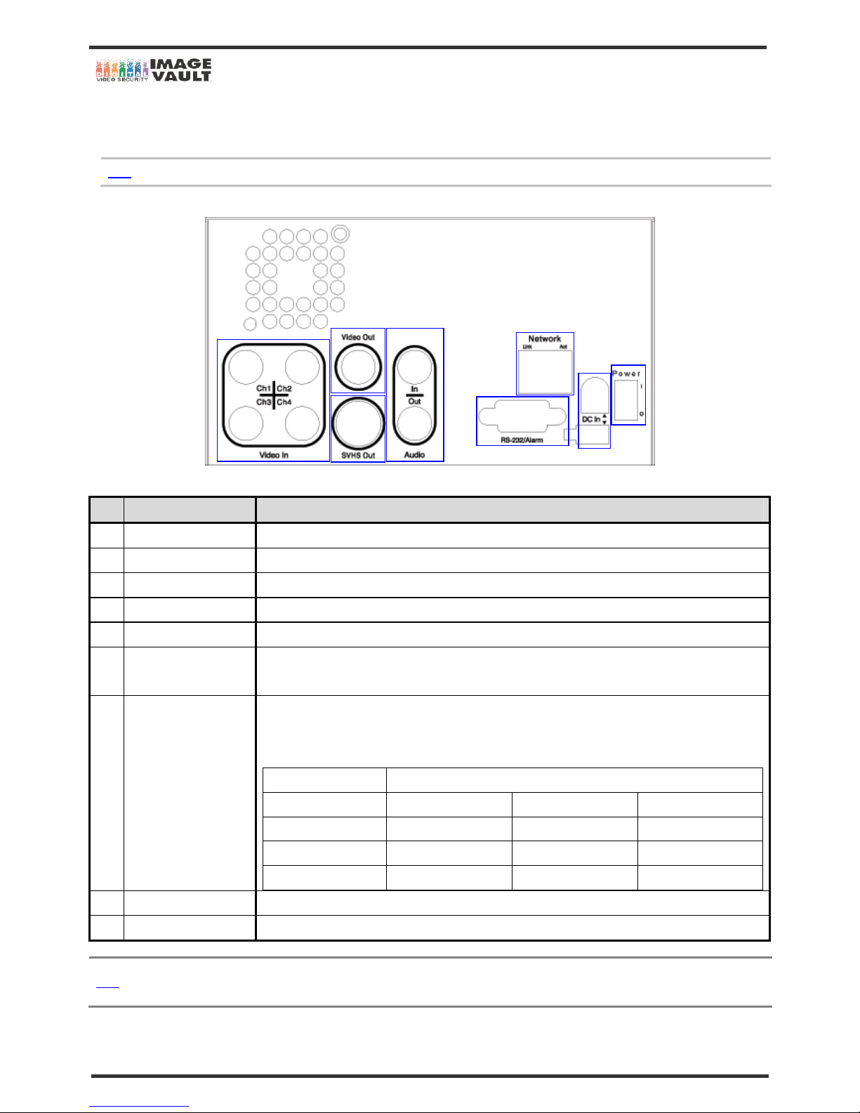
2.2 Rear Panel
The following is the rear panel of the DVR.
Note
The configuration differs according to the model.
No. Name Functions
1 Camera Input (BNC)
Connect to Camera (supports NTSC/PAL)
2 Monitor Out (BNC) Connect to the main monitor for camera image surveillance/management/playback
3 S-Video Secondary main monitor output
4 RS-232 Serial port to communicate with PC through RS-232 cable
5 Alarm/Relay Connector for alarm and relay
6 LAN Port
RJ-45 socket for 10/100 Ethernet connection. Link LED is lit when DVR is connected to the network. And Act
LED is lit when the network connection is through 10Mbit.
7
Adaptor (DC 12~30V)
Connector
DVR requires DC 12~30V adaptor. Do not use any other adaptors unless, it is approved by the dealer or
installer. Please use the one supplied only. Large capacity HDD requires high voltage adaptor. See below
table for more information.
HDD Capacity
DC Adaptor Under 120GB Under 200GB Under 400GB
12V (3A) Supported - 18V (2.5A) Supported Supported -
24V (1.5A) Supported Supported Supported
8 Power Button Use to turn the Power On/Off.
9 Power Switch Power Switch
Note
Ensure that the specification of the DVR agrees with the specification for the peripheral devices. For details about adding additional
peripheral devices, consult your dealer or installer
134
5
6
7
8
2
9
Page 12
Mobile DVR - Installation Manual
12/47
3. INSTALLATION
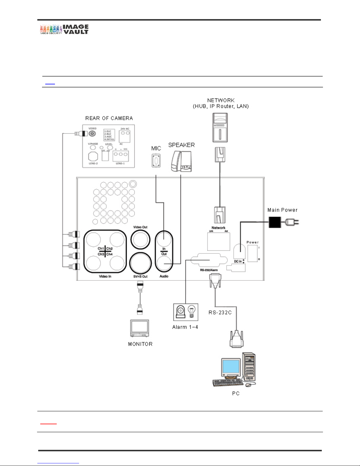
3.1 Connecting Peripheral Devices
This section describes how to efficiently hook up peripheral devices for usage with the DVR. Install the DVR on flat surface.
Note
Install system in location with good ventilation to prevent overheating.
Caution
Depending on the grounding, the coaxial cable connecting to the camera has danger of electric shock. Shut down power of th e
system completely (unplug the power cable) before connecting video cable to BNC port.
Page 13
Mobile DVR - Installation Manual
13/47
3.1.1 Camera Input
Connect the BNC plug of camera or video source into desired BNC connector on rear of DVR.
3.1.2 Monitor Out
Connect the BNC cable of the monitor to ‘Video Out’ BNC connector of the rear panel.
3.1.3 SVHS Output
One additional main monitor can be installed by using the S-Video output. If the monitor has an S-VIDEO input and cable, then connect to
SVHS Out. SVHS out gives better picture quality. Or incase the user wants to connect to each individual monitors for simultaneous
operation, then connect two monitors into ‘Video Out’ and ‘SVHS Out’ connector.
3.1.4 Serial Port
This is a port for RS-232 signal output. RS232 connector provides DVR for remote viewi ng, firmware upgrade, etc. Use a cable (Direct
Cable) that we provided with the unit. Connect the cable between ‘Connector’ on DVR and ‘COM PORT’ on PC.
3.1.5 Ethernet 10/100
Connect RJ-45 jack of LAN cable to LAN port. Network has to be TCP/IP base 10/100BASE-TX Ethernet LAN (Local Area Network),
Internet or exclusive line, and IP address should be fixed one. Network function of DVR can retrieve images from across the network usin g
10/100Mb Ethernet Connector. Software can bring the images directly from DVR and save them in JPG or AVI file format. Consult the
installer for proper network configuration.
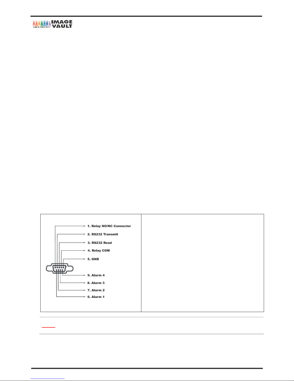
3.1.6 ALARM & RELAY
To connect an alarm or sensor, consult your installer or supplier for more information.
Connect 9-Pin D Sub male connector to Serial Port of th e DVR. An d conn ect senso r (dry contac t type) . Separa te the te rminal block and wire all
devices to desired pins. Connect each ground (GND) line to “GND” pins. See the below diagram for pin description.
① To make connections on the Alarm Connector Strip, place the strip on
appropriate position. (See the drawing on left side)
② Do soldering between the strip and pin.
Caution
You cannot connect more than AC125V, 0.3A in Alarm Output. In other word, you cannot use alarm that has a power more
than AC125V.
Page 14
Mobile DVR - Installation Manual
14/47
3.1.7 Audio Input and Output
Connect Audio out device to Audio Output connector and connect Audio input device to Audio Input connector.
It is the user’s responsibility to determine if local laws and regulations permit recording audio.
CAUTION
Input voltage of audio input device is line level and it should not be an audio input through the microphone.
Use of audio output device with an amplifier is recommended.
3.1.8 Power Input (Using as normal DVR)
Connect to main power cord of the system. The user must use the adaptor that has been given by installer.
Before plugging-in the power cord to the system, check if the power is in accordance with the system specification (Singl e
Phase AC 100~240V)
CAUTION
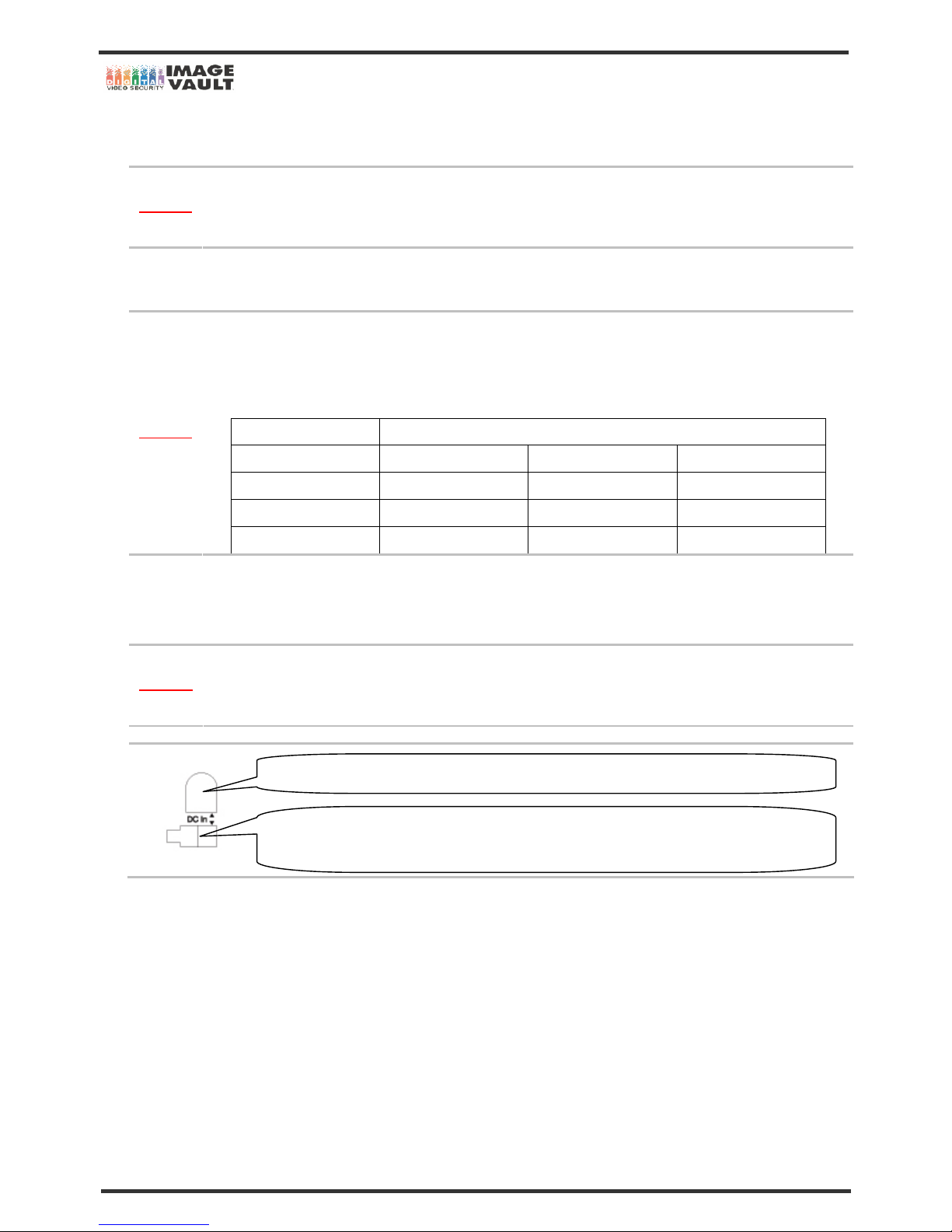
The DVR can support a 120 GB or above HDD IF, AND ONLY IF you use 18V, 2.5 Ampere adaptor. If you use 12V, 3
Ampere adaptor, the DVR may not detect the HDD. See below table for more information.
HDD Capacity
DC Adaptor Under 120GB Under 200GB Under 400GB
12V (3A) Supported - 18V (2.5A) Supported Supported 24V (1.5A) Supported Supported Supported
3.1.9 Power Input (Using as mobile DVR)
Connect the power wire to vehicle power. The power has to be between DC 12V to DC 30V. Please connect the wire to vehicle power in
order to use the DVR.
One is 12V ~ 30V. And another one is for ground. Check the cable before plugging.
CAUTION
To connect the power, you will need 5566 Wafer from Molex (Model Number: 5015TW-2S-W). Please contact installer for
more information.
For normal use: Connect supplied adaptor.
For mobile use: Connect power wire to the connector. Left slot is for + (PWR) and right slot is for –
(GROUND).
Page 15
Mobile DVR - Installation Manual
15/47
3.1.10 Direction Key Button
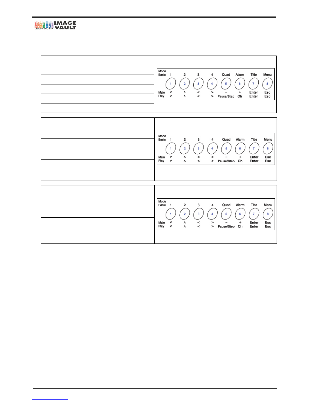
The direction button activates differently for Previewing Mode, Playback Mode, Menu Setup Mode.
On Previewing Mode
No.1 Button: Select Channel 1
No.2 Button: Select Channel 2
No.3 Button: Select Channel 3
No.4 Button: Select Channel 4
No.5 Button: Select Quad Screen.
On Playback Mode
No.1 Button: Decrease playback speed
No.2 Button: Increase playback speed
No.3 Button: Play backward
No 4 Button: Play forward
No.5 Button: Pause the screen and play frame by frame.
Setup Menu, Search Menu Mode
No.1, No.2, No.3, No.4 Button: To Move direction
No.5, No.6 Button: To change the value
No.7 Button: Use this button to enter submenu, go to the next
stage or set value. And press this button to save the Menu
changes.
Page 16
Mobile DVR - Installation Manual
16/47
3.1.11 Portable Controller
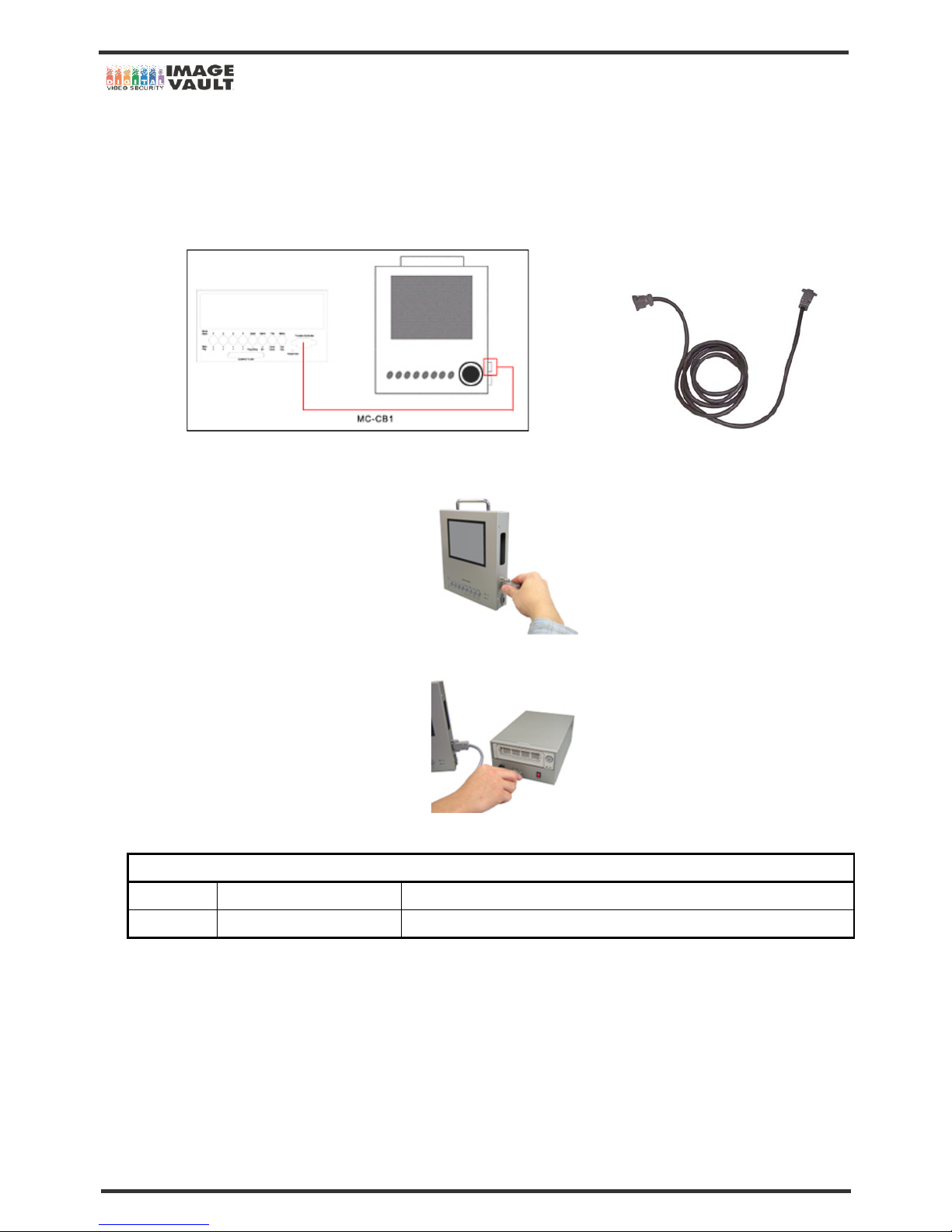
Setting the menu or direct playback from the vehicle can be done with portable controller.
The buttons on the front panel of the portable controller have exactly same functions as the DVR buttons. Connect the 15 PIN cable (MCCB1) which is supplied with the portable controller. Follow the below instruction to connect Portable Controller.
* Portable Controller connector (15 Pin D-SUB Connector): This connector is to connect between the DVR and Portable Controller.
Picture 1: MC-CB1 Cable connected between the DVR and Portable Controller 15 Pin D-Sub Cable (MC-CB1)
1. Connect the cable to ‘To DVR Main’ connector on the right side of Portable Controller.
2. Connect the other end to ‘Portable Monitor’ connector on the front panel of DVR.
3. Turn on the power of the DVR.
Jog-Shuttle Description
Jog Center Circle of Jog-Shuttle Search image backward or forward frame by frame
Shuttle Outer Circle of Jog-Shuttle Fast search backward or forward (X2, X4, X16, X32, X256, X1024, X8192)
* To play normal speed (X1) with Jog-Shuttle, turn Jog and leave in-between ticks
Page 17
Mobile DVR - Installation Manual
17/47
3.1.12 Switching NTSC or PAL
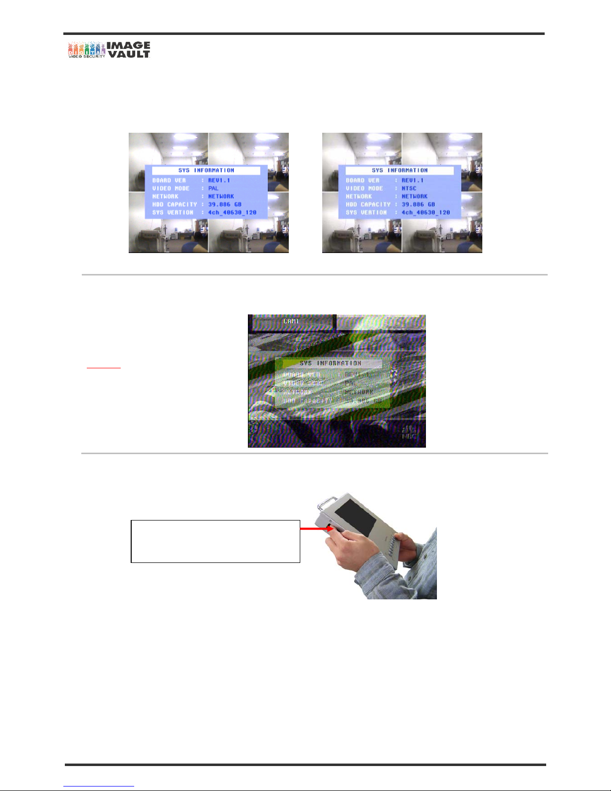
The DVR can be used with either NTSC or PAL mode. The system will automatically detect the video mode from channel 1 video source. If
the camera 1 sets as NTSC mode, the system will turn to NTSC mode.
VIDEO MODE switched to PAL MODE VIDEO MODE switched to NTSC MODE
CAUTION
If the user had set the mode wrong or the monitor does not suppor t different video mode, the screen may be in blan k or the
screen will be displayed as below.
To switch Portable Controller to PAL or NTSC mode, toggle the switch on the left side of Portable Controller.
NTSC or PAL switch: There is a switch located
on the left side of the Portable Controller
.
Page 18
Mobile DVR - Installation Manual
18/47
3.2 System Startup and Shutdown
3.2.1 System Startup
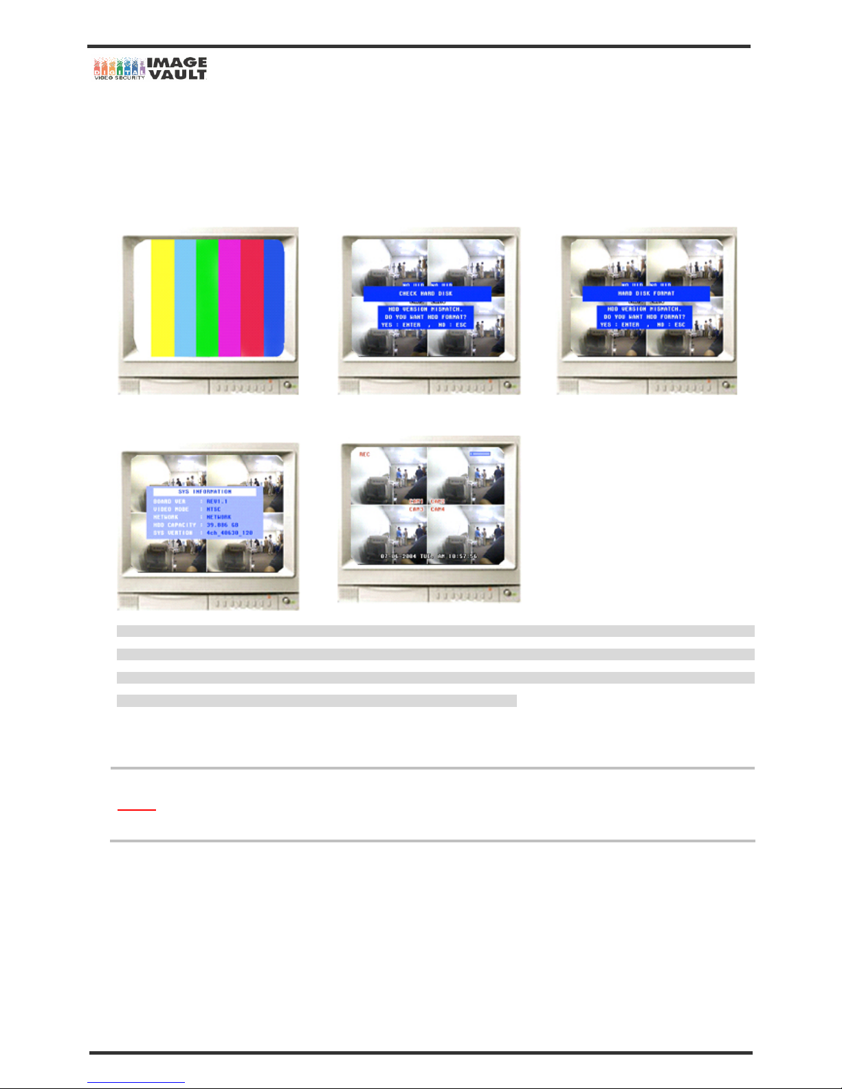
After connecting all peripheral devices, connect the power to the DVR for system startup. The power will be turned on immediately and the
unit will begin to check the HDD and will record immediately. The following message will be displayed on the middle of the screen.
1
st
2
nd
3
rd
4
th
5
th
WARNING: The DVR uses the time and date to index video on HDD that is how you find and view the images later. Changing time and
date can cause the DVR to work improperly when you try to play back video. If you set the hour ahead, this is not a problem. But if yo u set
the hour back there will be more than one recording at same time. Therefore, you need to be careful to date and time setting. I f the time is
incorrect when you install the unit, then we recommend you to set the time immediately.
3.2.2 System Shutdown
To turn off the power, press the power button for proper shutdown of the system. Do not turn off the power by pulling the power plug.
Caution
In case the power plug is pulled off while the system is operating, the currently recording file may not be closed properly. In
addition, even though index file is not damaged, index information required for quick file search may be not saved. Therefore,
turn off system power by pressing the power button to prevent malfunction.
3.2.3 Countermeasures after abnormal shutdown
The DVR has been designed to operate for long periods without a problem.
The operation of the system can be locked up however, when major parts (such as hard disk) function abnormally due to external electric
shock, physical damage, or other various reasons.
The system stops operating during abnormal situations, and the internal watchdog circuit is activated in order to reset the system for
rebooting within 10 seconds. The system will then recover normally. However, if major parts (such as hard disk) are physically damaged, it is
impossible to recover normally. This will cause continuous rebooting by watchdog or deadlock without reset.
Page 19

Mobile DVR - Installation Manual
19/47
3.2.4 Heart Beat Function
There are occasions where system does not come back from the failure even after reset. For example, from effect of strong surge or ESD
into the system can cause system halt and not be able to function. To prevent the occurrence of such cases as above, DVR has applied
Heart Beat Module into DVR’s inner architecture. If DVR encounters complication within 1 or 2 minutes then the Heart Beat function rush
out forward. Heart Beat function is working; means it has ability to put power off and on. If Heart Beat is operating properly then, Heart Beat
will automatically turn power off and on the system accordingly.
DVR are originally designed and developed for installing in automotive purpose. Therefore, our units obtain much more solid system than
other CE approved products. Also, DVR surge resistance level is much higher. Therefore, when there is strong surge or system halt attempt
to defect our product’s performance, Heart Beat will be there to bring the system back to normal.
Page 20
Mobile DVR - Installation Manual
20/47
4. REMOVABLE HDD INSTALLATION
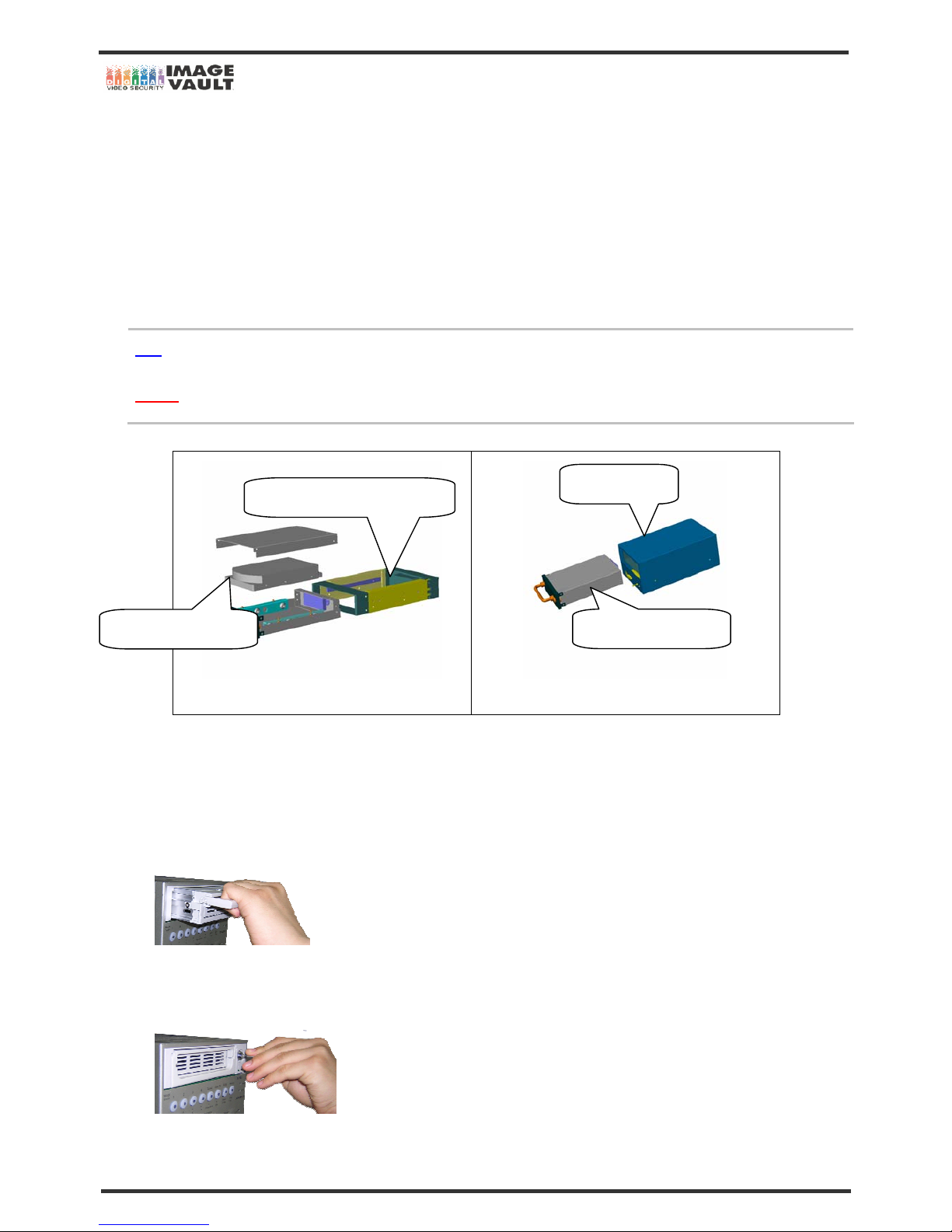
The DVR is equipped with a removable HDD and you must install the HDD before operating the unit. Additional removable HDD can be
purchased at your local PC shop or ask your supplier. You can use a HDD as a Video Tape. You can keep them for some while and reuse them
again.
4.1 Installing New HDD
Directly above the front panel buttons is removable hard disk drive slot. Hold the HDD and slide it gently into the slot until it stops. And pul l
down the handle and you will feel it getting locked. And put removable HDD rack key and turn it to right.
Note
You must lock the removable HDD case in order to operate unit. If you do not, the D VR cannot detect HDD.
Caution
When you upgrade the DVR with new firmware, DVR will delete all the data that has been recorded on HDD by old firmware
version. Make sure that you know about this before upgrading the new firmware.
Diagram 1 (Break down of Removable HDD)
Diagram 2 (DVR with removable HDD)
4.1.1 Installing Order
Please follow the following steps to install HDD.
1. Directly above the front panel buttons is removable hard disk drive slot.
2. Hold the HDD and slide it gently into the slot until it stops.
3. Pull down the handle until you will feel it getting locked.
4. Put removable HDD rack key and turn it to left.
Removable HDD Box
3.5” Hard Disk Drive
Removable HDD Box Enclosure
DVR Main Body
Page 21
Mobile DVR - Installation Manual
21/47
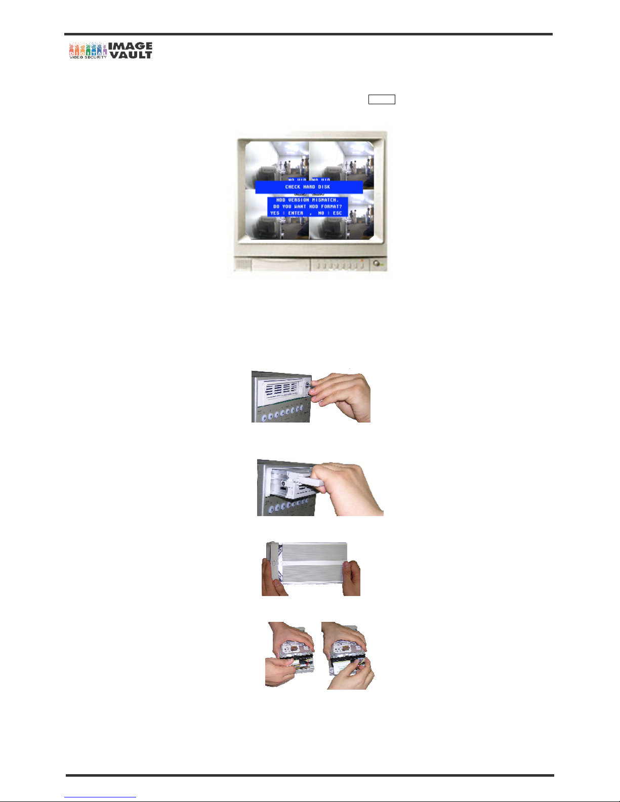
5. Installation is now done. Turn on the DVR. If it is the new HDD or the HDD that has been used in other DVR or PC, the DVR will ask
you to format the HDD in order to use in our system. To format the HDD, press ENTER button or if you have important images or data,
press ESC and back up the data before you use.
4.2 Replacing HDD
Please follow the following steps to replace HDD.
1. Turn off the power of the DVR.
2. Unlock the removable HDD by turning the key to the right.
3. Pull up the lever of removable HDD and pull it out gently.
4. Open the top by sliding gently against the handle.
5. Insert HDD and connect 40 PIN cable and power cable to HDD.
Page 22
Mobile DVR - Installation Manual
22/47
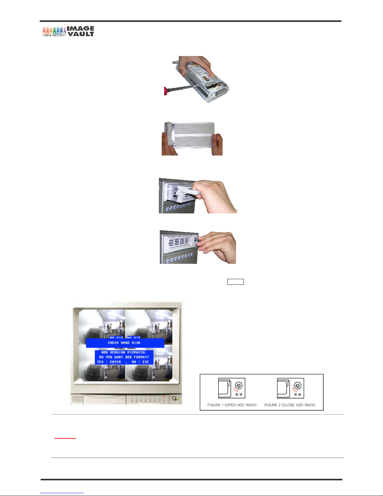
6. Put two screws on each side to secure the position of HDD.
7. Close the top by sliding the cover.
8. Hold the HDD and slide it gently into the slot until it stops.
9. Put removable HDD rack key and turn it to left to lock.
10. Installation is now completed. Turn on the DVR. If it is the new HDD or the HDD that has been used in other DVR or PC, DVR will ask
you to format the HDD in order to use in our system. To format the HDD, press ENTER button or if you have important images or data,
press ESC and back up the data before you use.
CAUTION
Your DVR is now ready to operate. The DVR cannot be turned on if the Hard Disk Drive door is not locked. If after installing
the unit properly but the DVR displays ‘HDD NOT FOUND’ on the top left corner of the screen, it is most likely that the HDD
is not installed properly or the HDD rack is not locked. Please make sure that the HDD rack is locked and restart the system.
If you still see the display, install the HDD again or contact your supplier.
Page 23
Mobile DVR - Installation Manual
23/47
5. DVR READER INSTALLATION & EXTERNAL HDD DEVICE INSTALLATION
5.1 Installing Software
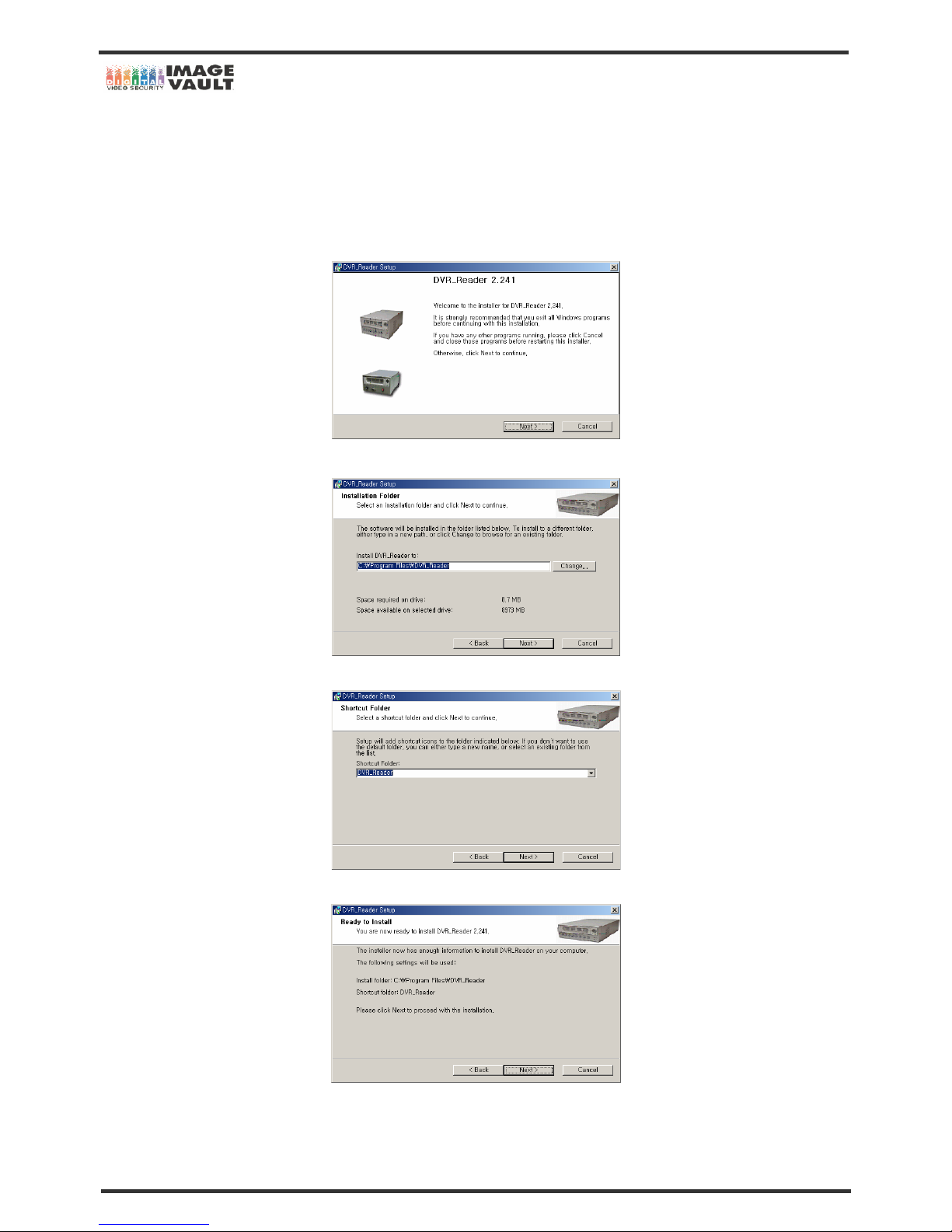
You will find an installation CD from DVR. Please select DVRReadersetup.exe and run the file.
1) When you run the file, you will see below diagram on your monitor. Click Next to continue.
2) Click Next button again and next step is to select the installing directory. Please select where you want to install the software.
3) You can make the shortcut of the software. Please select the name of shortcut.
4) When you click Next button, it will ask you to confirm the directory and name of short cut. Click Next to start installation.
5) Installation is complete now and the software will be started when you click the Finish button.
Page 24
Mobile DVR - Installation Manual
24/47
5.2 Installing External HDD Device
In order to use and view the recorded material on PC, you will need to install one of following installation.
- HDD Rack Frame Installation
- Using IEEE-1394 External HDD unit installation
- Using USB 2.0 External HDD unit installation
Each option requires optional items. Please read the below descriptions and choose one of following option.
CAUTION
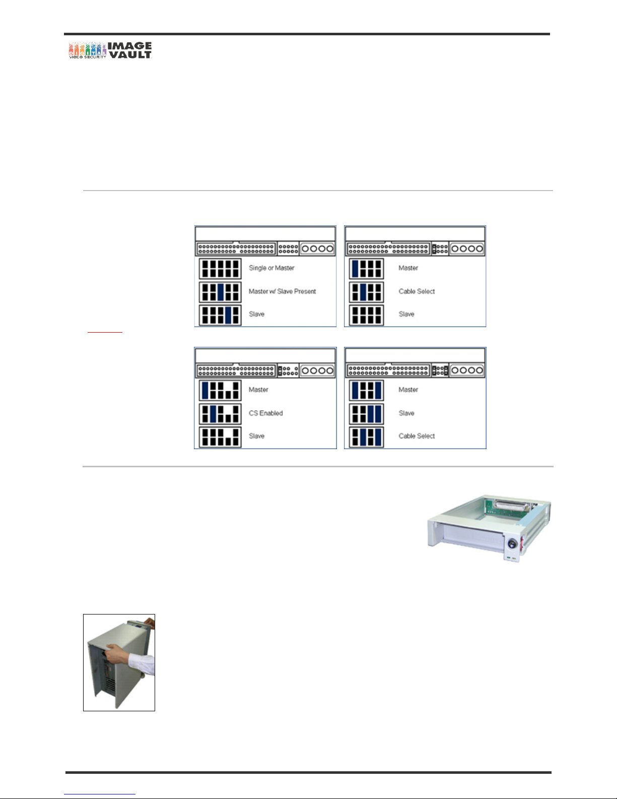
The HDD installed in DVR is in MASTER mode. Please leave the jumper setting unless you ask to. Changing jumper mode
may cause the failure of reading HDD. Please see the below for each manufactures jumper setting.
Western Digital Jumper Setting Mode Seagate HDD Jumper Setting Mode
Maxtor Jumper Setting Mode Hitachi Jumper Setting Mode
5.2.1 Using Hard Rack Frame
This option is recommended for users who use Removable drive. You need to make sure that
your PC has an empty slot to install HDD rack frame.
To use this option, user needs HDD Rack Frame. In order to view the image on the PC
conveniently, user can install the HDD rack frame in the PC. By doing this, you can directly insert
the removable HDD to the PC. No need to take the PC case off every time.
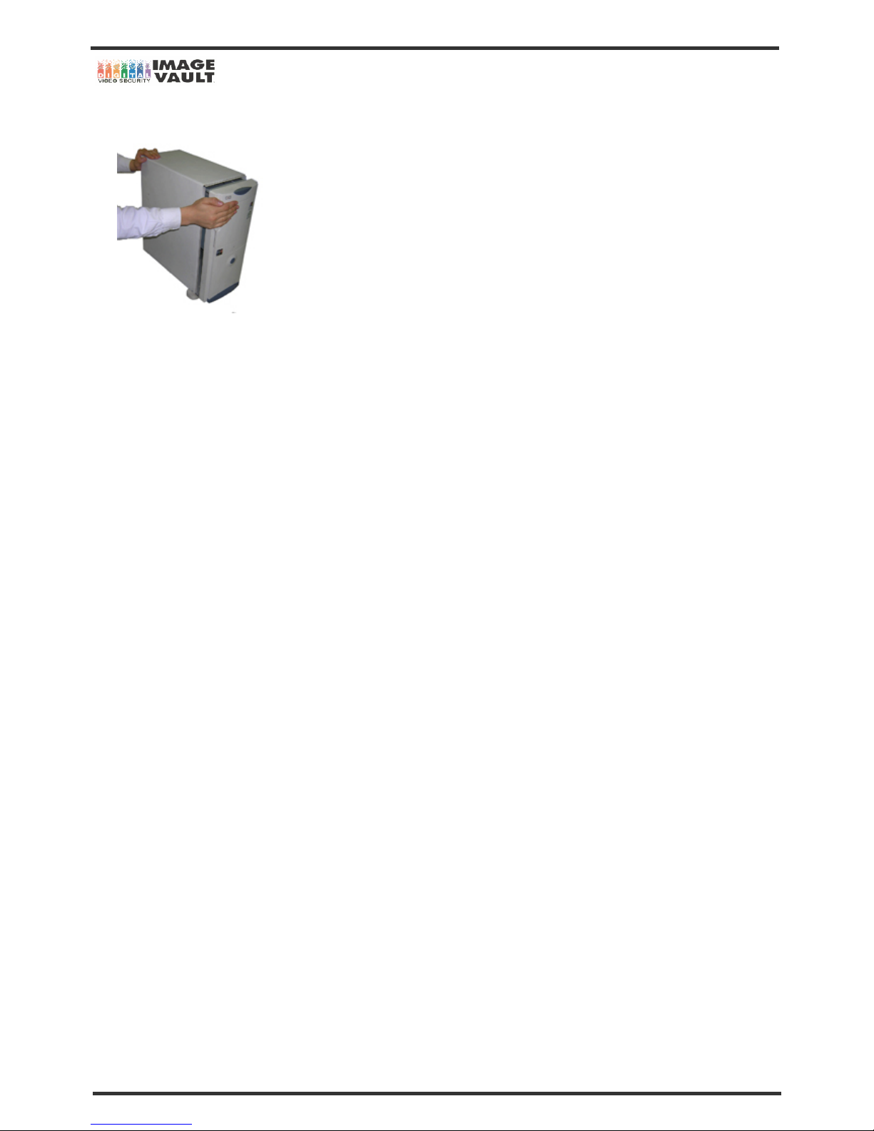
1. Unplug all the cables that connected to PC. Take off four or six screws at the back and push and slide the top case backward as shown
on below picture. The method to take the top case off is different for each case.
Page 25
Mobile DVR - Installation Manual
25/47
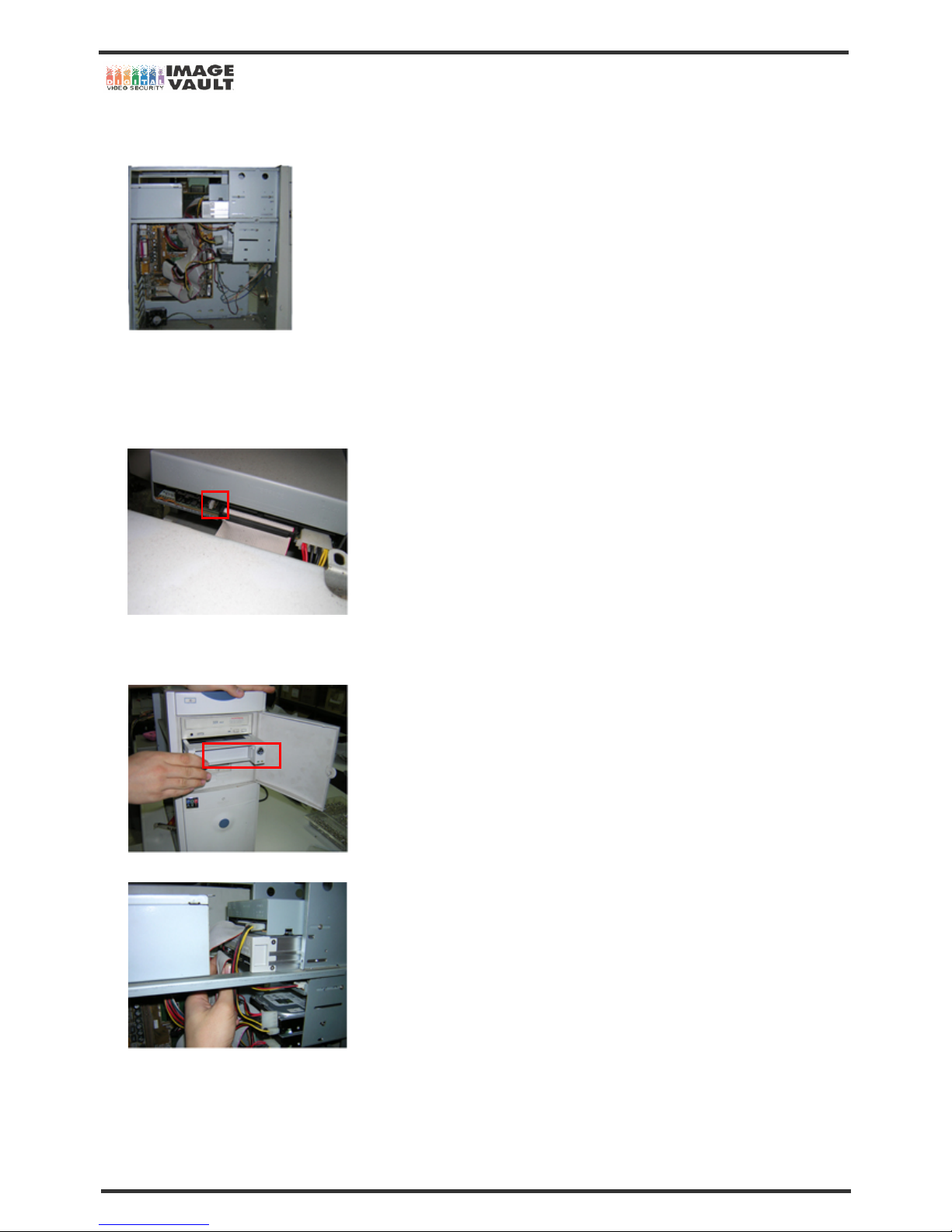
2. When you open the case, you will find the empty slot to install extra HDD Rack frame or CD Rom. The empty slot is located in different
position.
3. Right above or below of CD Rom, you will find an empty slot to install HDD rack frame. You will have to install the rack frame in that
position. You need to adjust the jumper setting for Rack frame as well as installed CD Rom. The CD Rom th at was already installed in PC
should be set as MASTER mode. And you need to set it as SLAVE mode and set MASTER mode for the rack frame. Take off the 40-Pin and
power cable of CD Rom and change the jumper mode. The below picture is where you set jumper mode.
4. When you set the jumper mode for CD Rom (SLAVE MODE) and Rack Frame (MASTER MODE), you need to insert the rack frame as
below picture. Ever if you change the jumper mode, you can use the CD Rom just like you used to.
5. Connect the 40-Pin Cable and power cable as shown on below picture. Check the jumper mode once again.
6. Tighten two screws each on both sides to secure the rack frame.
Page 26
Mobile DVR - Installation Manual
26/47
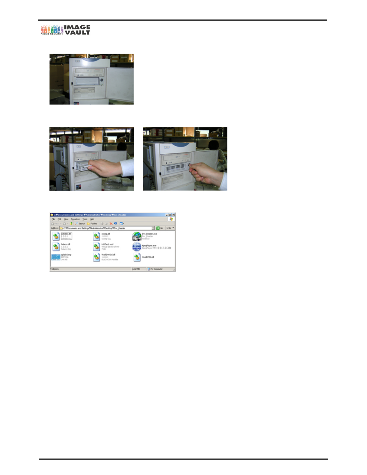
7. Rack frame installation is now done.
8. As shown on below picture, insert the HDD and lock the case. If you do not lock the case, the PC will not detect the HDD. Once yo u start
the system, the OS will automatically detect the HDD. And please do not insert or take out the HDD when the PC is on.
9. HDD installation is complete. Turn on the power and run DVR Reader (double click on Dvr_Reader.exe). See the next chapter for
information on how to use the program.
Page 27
Mobile DVR - Installation Manual
27/47
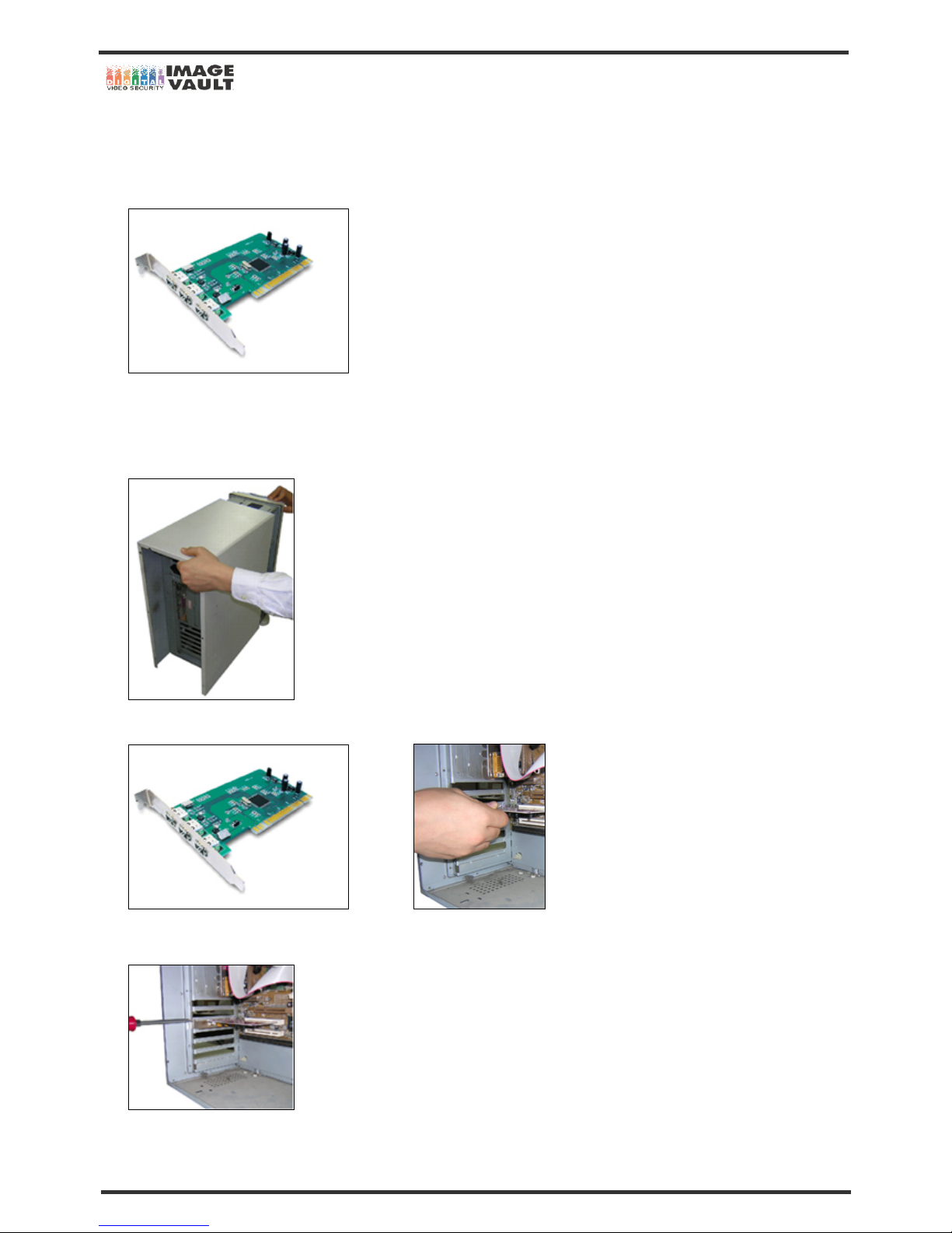
5.2.2 Installing IEEE-1394 Card
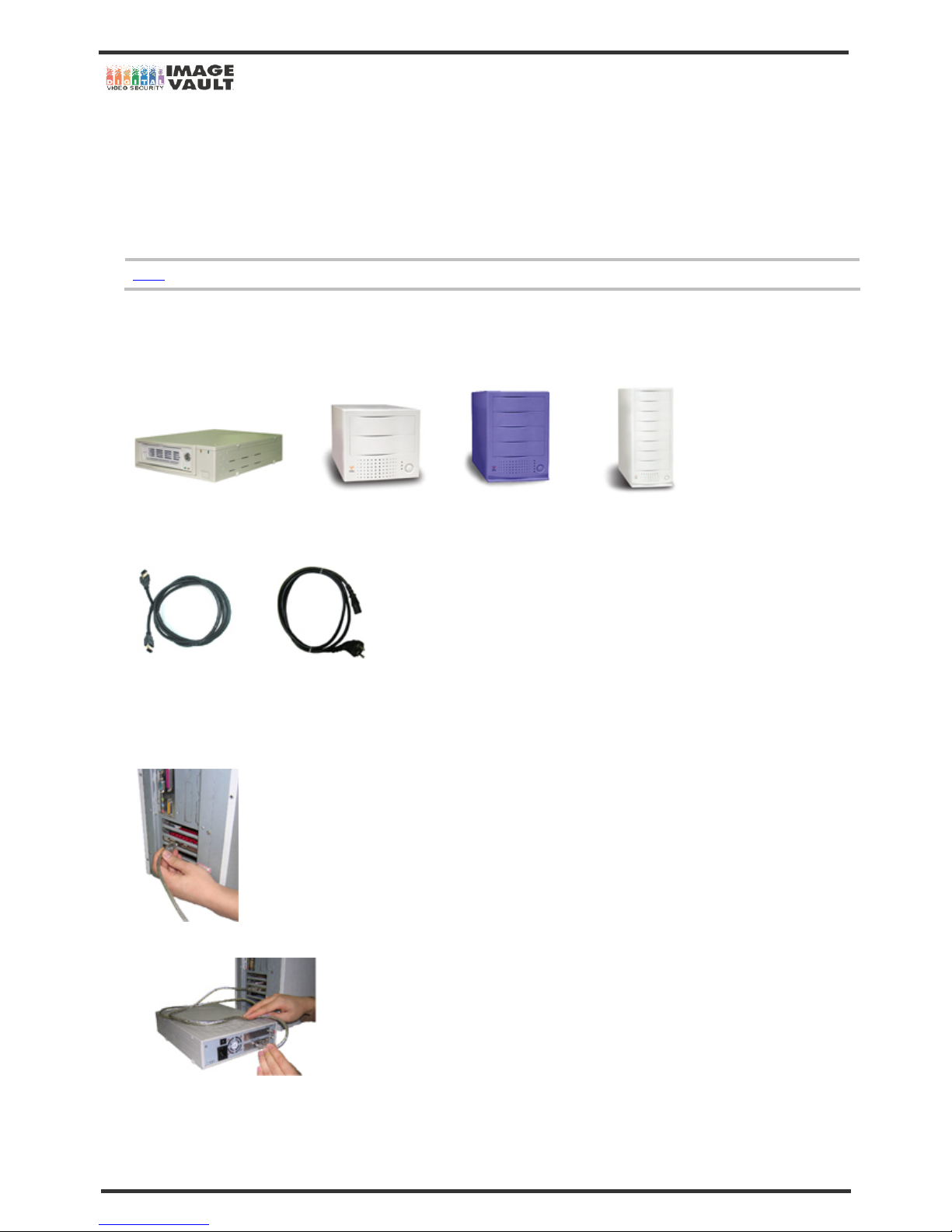
Installing IEEE-1394 card is essential if you want to use 4 or 8 slot external IEEE-1394 drive. Main PC must have the IEEE-1394 Int erface
Card to install External HDD Rack Case. You need an IEEE 1394 Interface card for installation.
1. Open the top case of PC. Unplug all the cables (Mouse cable, Keyboard cable, etc) that connected to PC. Take off four or six screws at
the back and push and slide the top case backward as shown on below picture. Method may be different depends on which cases you are
using.
2. Insert the IEEE1394 to empty slot on the main board.
3. Tighten up the screw as shown on the below picture.
Page 28
Mobile DVR - Installation Manual
28/47
4. Put the case back on and connect all the cables that had been connected with PC.
- Microsoft® Windows™ 2000 or latest version of OS will automatically detect the IEEE 1394 card. If the PC asks you to install the IEEE
1394 Driver, please install the Driver before you use.
Page 29
Mobile DVR - Installation Manual
29/47
5.2.3 Installing External HDD Rack Case
After installing IEEE-1394 card, you need to install the Rack Case. Rack Case is needed to play many Hard Disk Drives at once. Also, it
helps users to use software more easily. At the time of writing, Rack Cases are available with single bay, 2 bays, 4 bays and 8 bays.
You will need following items to continue the Rack Case installation;
- Rack case (Single Bay, 2 Bays, 4 Bays or 8 Bays) - IEEE 6:6 1394 Cable X 2 or X4 - Power Cable
NOTE
If you want to use 8 bays Rack Case, you need to install two IEEE-1394 Interface Cards
To use this option, user needs following items.
IEEE 1394 Interface Card
- Select one of right external hard disk drives. Each drives has different number of slots. Single, 2, 4 and 8 slots are available.
Cable for installation
- IEEE 6:6 1394 cable and power cable is needed for installation
Please follow the below instructions to install the Rack Case.
1. Connect IEEE 6:6 1394 Cable to empty slot on IEEE 1394 Card. Most of IEEE 1394 card has three slots. You can plug into any of empty
slots.
2. Connect the other ends to a connector on rear of external drive.
Page 30
Mobile DVR - Installation Manual
30/47
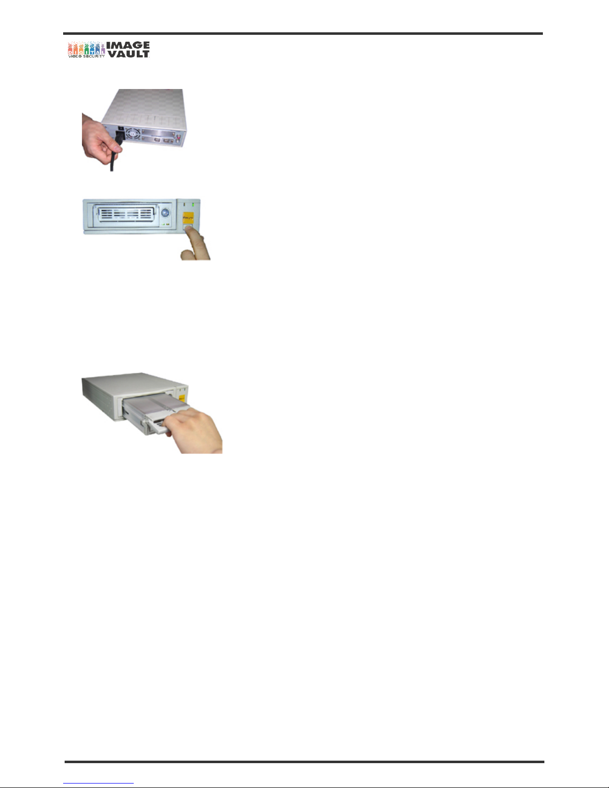
3. Connect power cord as shown on below diagram.
4. HDD installation is complete. Turn on your PC and external HDD drive.
IEEE-1394 Card and external HDD rack case is now installed. You just need to take out the HDD from DVR and put it into a slot on Rack
Case. Please follow the instructions.
5. Unlock the removable HDD rack with key provided with DVR. If it is Mini DVR, take out the HDD and place the HDD into Removable HDD
rack.
6. Lift up the handle and take out removable HDD from the DVR.
7. Insert the HDD rack into external HDD drive.
8. Run DVR Reader (double click on Dvr_Reader.exe icon). Software will detect the HDD automatically. See the next chapter for information
on how to us the program.
Page 31
Mobile DVR - Installation Manual
31/47
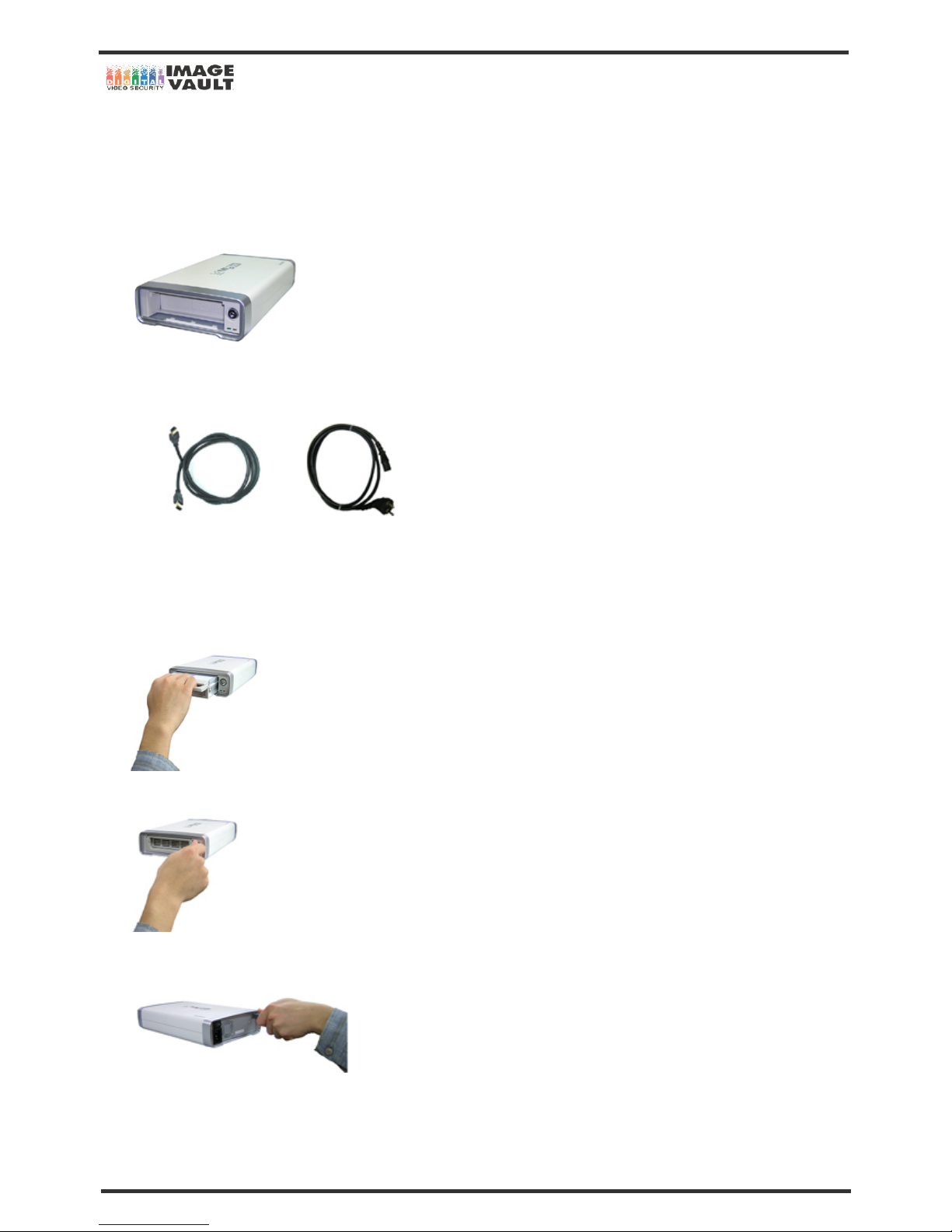
5.2.4 Installing USB 2.0 External HDD Drive
You will need following optional items to install USB external hard disk drive. Make sure you possess all the necessary items before
continue.
USB External HDD Drive: External HDD Drive for easy installation of HDD
Cable for installation
IEEE 6:6 1394 cable and power cable is needed for installation
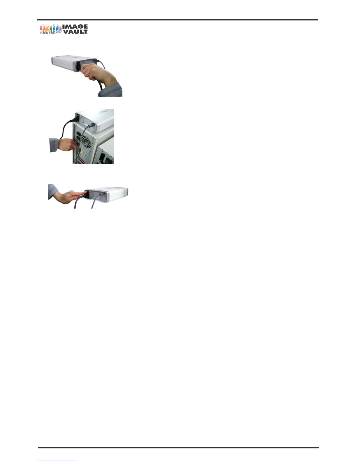
1. Unlock the removable HDD rack with key provided with DVR. If it is Mini DVR, take out the HDD and place the HDD into Removable HDD
rack.
2. Lift up the handle and take out removable HDD from the DVR.
3. Insert the HDD rack into USB external HDD drive. Otherwise you can insert the HDD later.
4. Lock the removable HDD rack with the key provided with USB external HDD rack set.
5. Plug USB Cable to the connector on the rear panel of USB external HDD drive.
Page 32
Mobile DVR - Installation Manual
32/47
6. Connect the power cord.
7. Plug the cable to USB port on PC.
8. HDD installation is complete. Turn on your PC and external HDD drive.
9. Run DVR Reader (double click on Dvr_Reader.exe icon). Software will detect the HDD automatically. See the next chapter for information
on how to us the program.
Page 33
Mobile DVR - Installation Manual
33/47
5.2.5 Installing USB 2.0 External HDD Drive with EZUSB
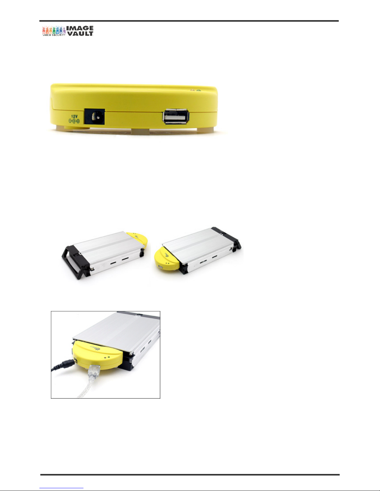
Our DVR hard-drives can be accessed through USB port by using EZUSB.
By simply attaching it directly to an inner-rack of hard-drive-rack, a normal IDE hard-drive can be transformed into an external hard drive.
Please follow below instruction to read the image from the HDD by using EZUSB.
1. Unlock the removable HDD rack with key provided with DVR.
2. Lift up the handle and take out removable HDD from the DVR.
3. Plug the HDD rack into USB external HDD drive as shown below.
4. Connect the power cable and USB cable. The power cable supplies power to the hard-drive with its 12V adapter, and USB cable
exchanges data between hard-drive and PC. (Power adapter is required since hard-drives require more power than USB cable provides.)
There are two status LEDs on the EZUSB. The green LED in the first picture shows whether the power is connected and the blue LED
blinks when the hard-drive is accessed.
Page 34
Mobile DVR - Installation Manual
34/47
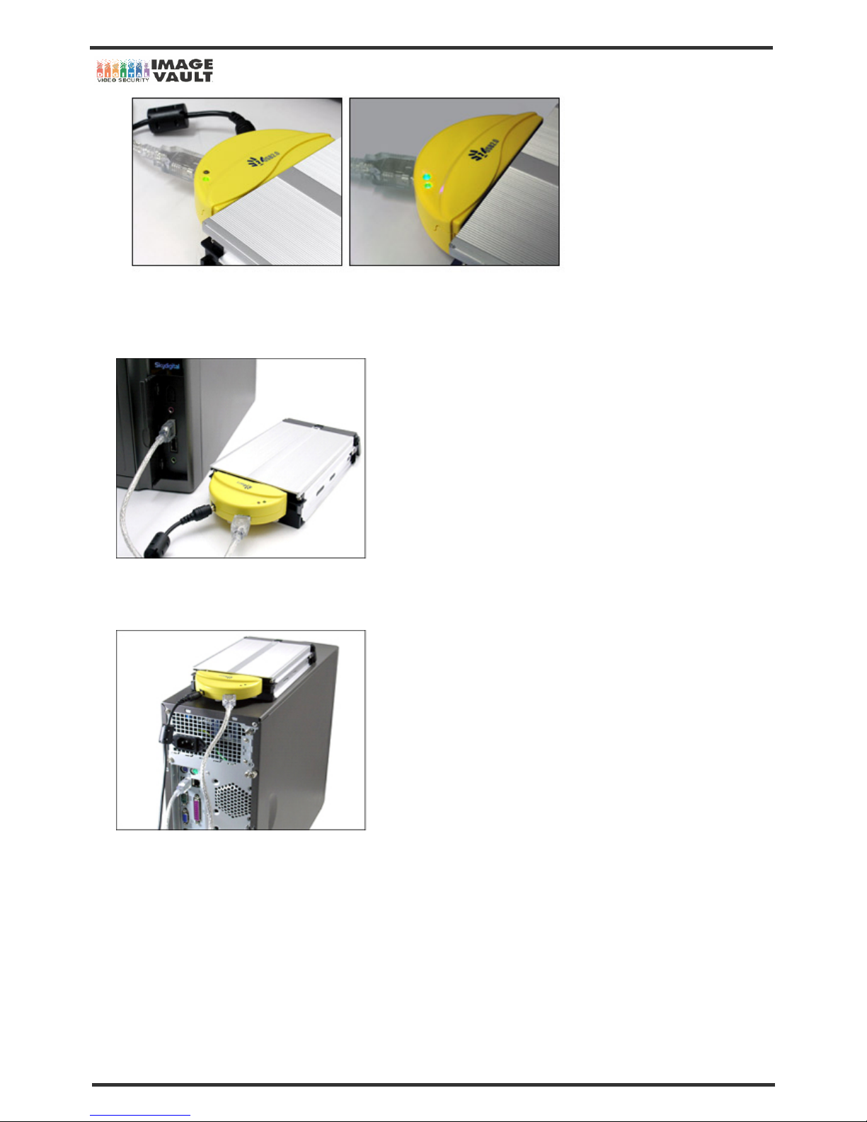
5. Connect the USB cable into any USB ports on the PC. By using EZUSB, our DVR IDE hard-drives can be easily connected to laptop or
desktop computers with USB port even though there are no hard-racks to be connected. If the computer supports USB2.0, the data can be
transferred as fast as 480Mbps.
6. After installing our DVR Reader from the CD that came with our DVR, connect the hard-drive to computer using EZUSB as shown above.
Once the hard-drive is connected properly, execute DVR Reader.exe on the desktop and the images from the hard-drive can be viewed.
* See DVR Reader Program Manual before you use the program.
Page 35

Mobile DVR - Installation Manual
35/47
6. Network Setup
In order to use remote viewing by software, DVR Manager, you will need to set up the following four operations. Please follow the instruction
below in step by step.
1. NAMEIP SERVICE SIGN UP
2. DVR’s DDNS SETTING
3. IP SHARING ROUTER SETUP (Only if you use IP Sharing Router)
4. DVR Manager (Remote Viewing Program)
6.1 What is DDNS?
DDNS provides a static domain name to those who have high-speed connections or use leased lines with a dynamic Internet Protocol
address.
A dynamic IP address resolves the problem stemming from the limited number of IP addresses. A dynamic IP address is given to users of
high-speed networks service and cable modems. Recently, even businesses that connect to the web through leased lines use DHCP d ue t o
depletion of IP addresses. Almost all the PCs have a dynamic IP address, which means that their IP address changes every time users turn
on their computer or log on to the Internet.
Domain Name Service (DNS) translates a domain name like www.yahoo.co.kr into a numeric IP address. However, the DNS system works
only with static IP addresses. For this reason, most of PCs with a dynamic IP address cannot provide various Internet services such as
running a homepage.
Using a dynamic DNS server, NameIP Service enables all the PCs with a dynamic IP address to have a domain name.
Page 36
Mobile DVR - Installation Manual
36/47
6.2 DDNS Sign Up
At the time of writing, user can select one of three DDNS service provider. If you are using dynamic IP, please select one from the three
providers and sign up.
NOTE
You may skip this part if you use Static IP.
6.2.1 IPUPDATER Sign Up
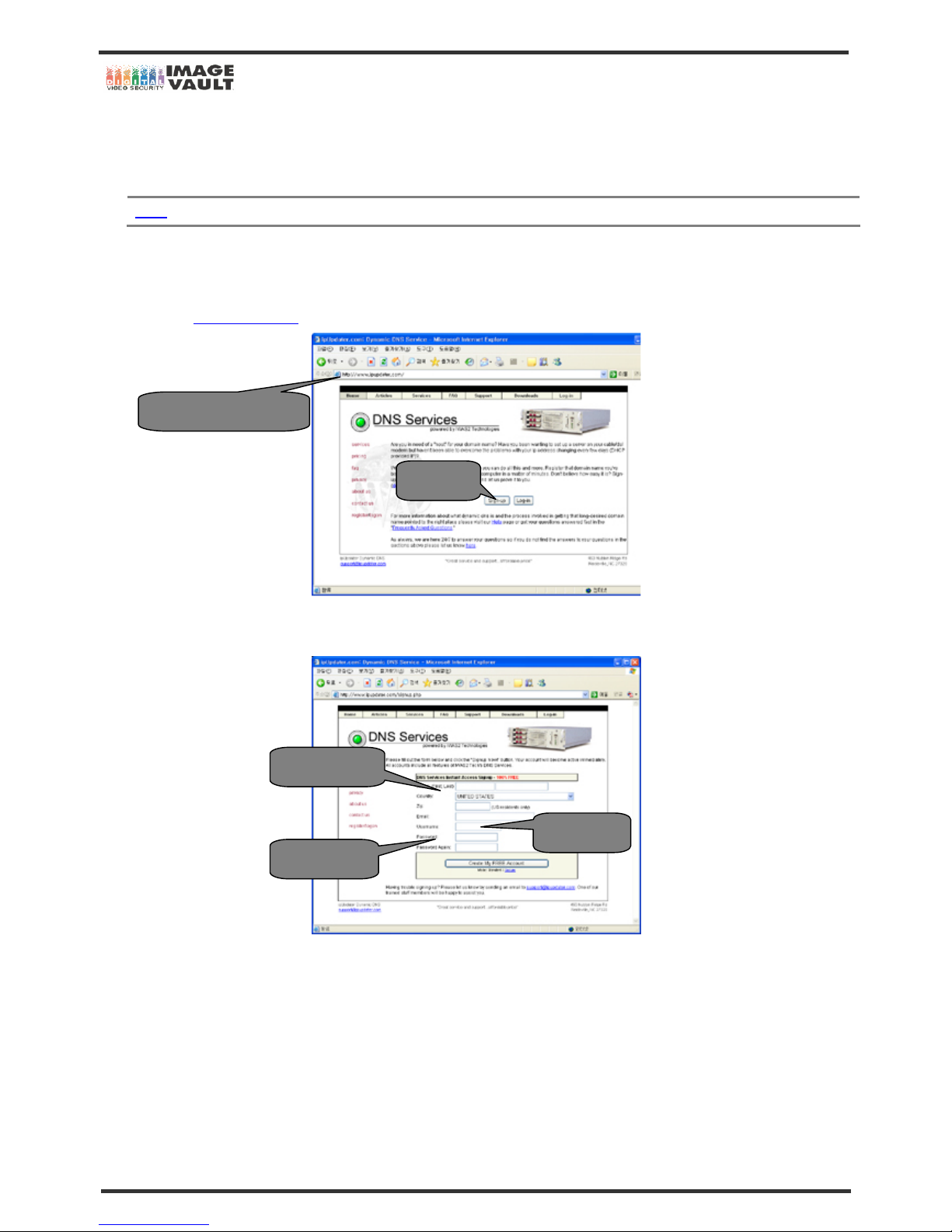
IPUPDATER.com is a company who offers DDNS service. Please read below instruction.
1. Log on to www.ipupdater.com/
. Default page as below is as below. Click on ‘SIGN UP’ to continue.
2. Once you click on ‘SIGN UP’, the below page can be seen. Please fill in the registration form. Your name, zip code and email address is
required for sign up. Type the user name and password. When the form is filled in, click on ‘CREATE MY FREE ACCOUNT’ button.
http://www.ipupdater.com
‘SIGN UP’
Put user ID
Put password
Personal Details
Page 37
Mobile DVR - Installation Manual
37/47
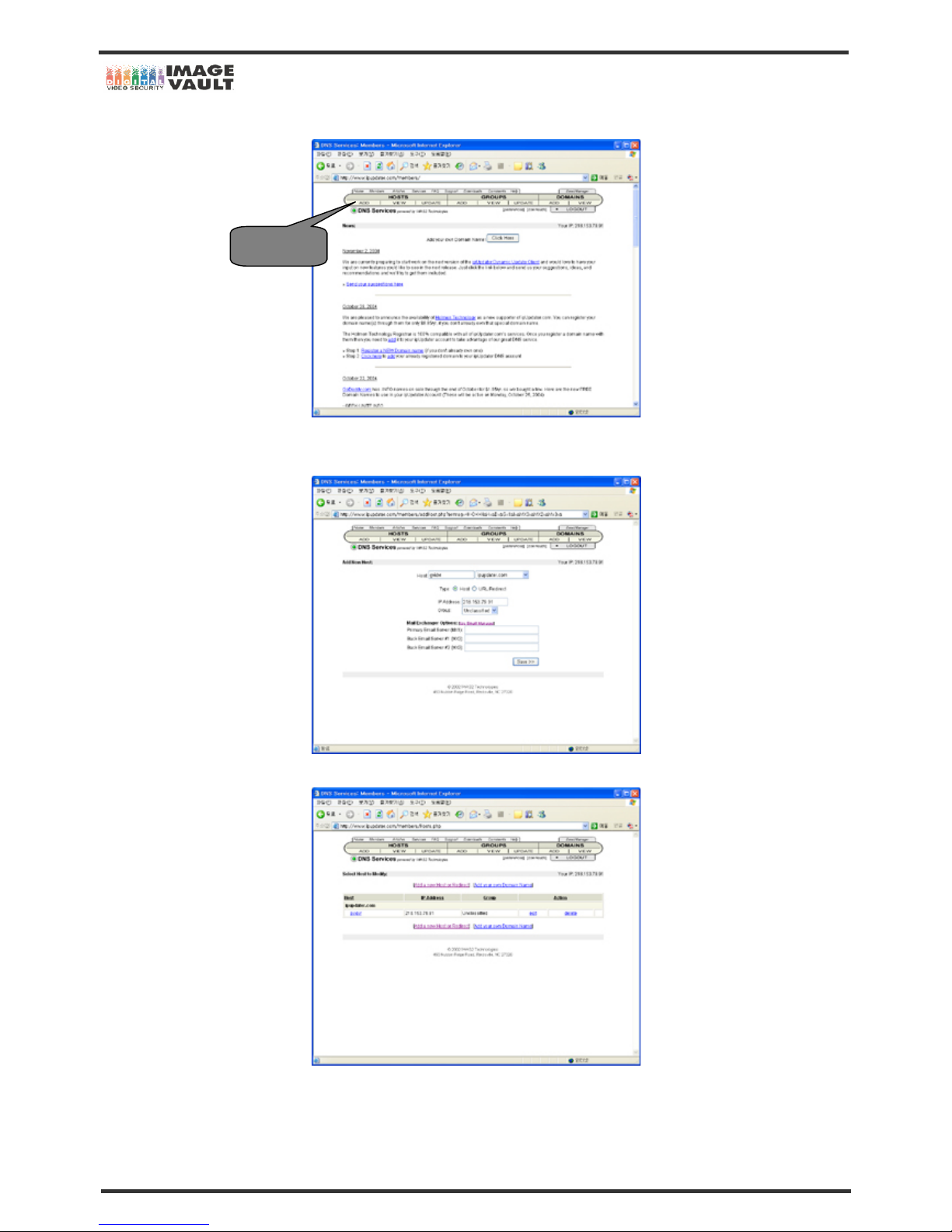
3. Sign up is now completed. Click the HOST ADD button on the left top corner of the website.
4. Type your ID on HOST section and you must leave the domain address field as ‘IPUPDATER.COM’. Leave the group section as
‘Unclassified’ and do not check other options.
5. The registration is now completed. Please print the page or make a note. You need the ID and Password for DVR setup.
Host Add
Page 38
Mobile DVR - Installation Manual
38/47
6.2.2 DNIP Sign Up
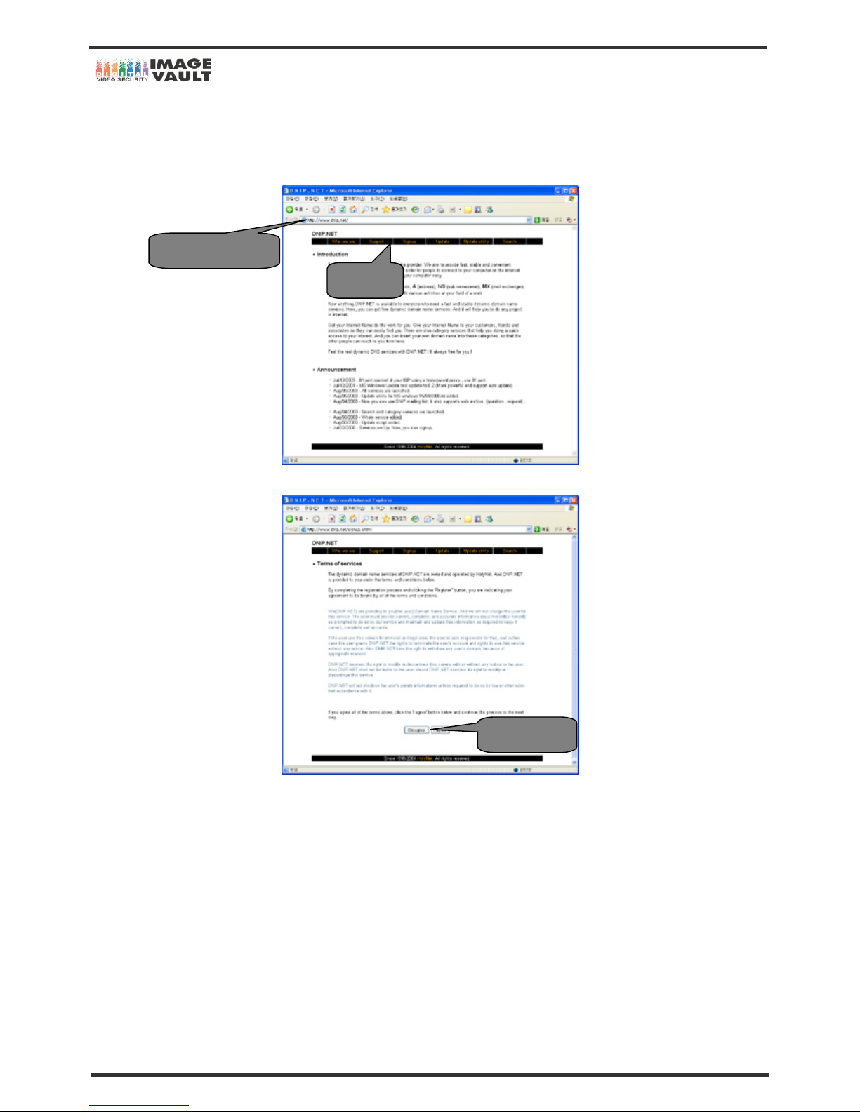
DNIP.net is a company who offers DDNS service. Please read below instruction.
1. Log on to www.dnip.net/
. Default page as below is as below. Click on ‘SIGN UP’ to continue.
2. Click ‘I AGREE’ after reading the service agreement.
http://www.dnip.net
‘SIGN UP’
I Agree Button
Page 39
Mobile DVR - Installation Manual
39/47
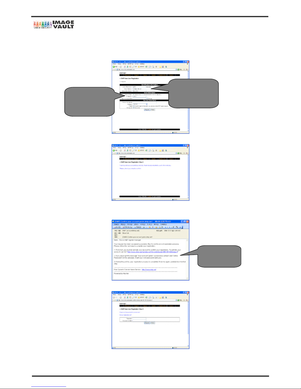
3. Once you click on ‘I AGREE’, the below page can be seen. Please fill in the registration form. Your name and email address is required
for sign up and type the user name. On HOST INFORMATION, choose ‘Address Only’ as Service Type and type ‘0,0,0,0’ on IP ADDRESS
section. You may type the service information. When the form is filled in, click on ‘REGISTER’ button.
4. User needs to check their email to finish up the sign up. Check the email that you typed on Registration Form.
5. User will receive an email from DNIP and the subject of the email will be ‘[DNIP] Confirm your account dvr.dnip.net!’. Click the link in the
email to confirm the registration.
6. Once you click the link on the email, Internet Explorer window will pop up on the screen as below. Type the password.
ID
Email Address
Your name is required.
Select ‘ADDRESS
ONLY’ and type the IP
Address as 0.0.0.0
Click to confirm the
registration.
Page 40
Mobile DVR - Installation Manual
40/47
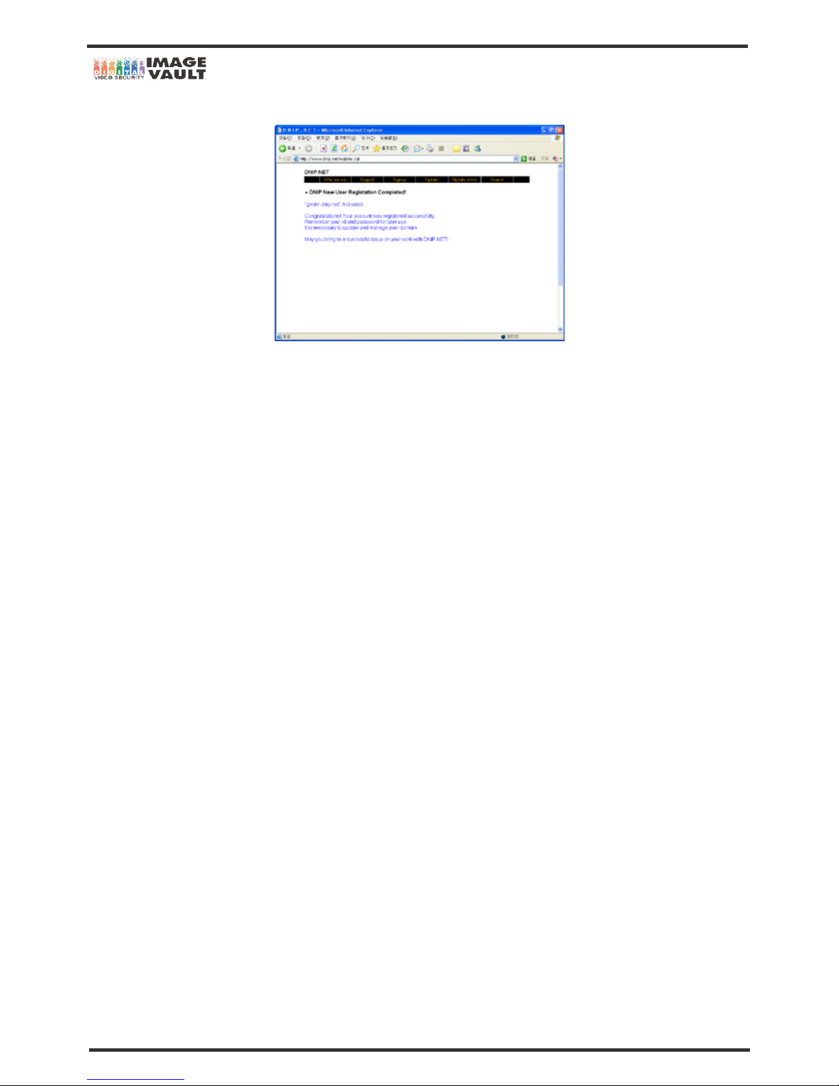
7. Registration is now completed. Please note your ID and password.
Page 41
Mobile DVR - Installation Manual
41/47
6.2.3 NameIP Sign Up
Name IP is a company who offers DDNS service. Below instruction is based on the Name IP sign up procedure.
1. Log on to www.nameip.com/english/
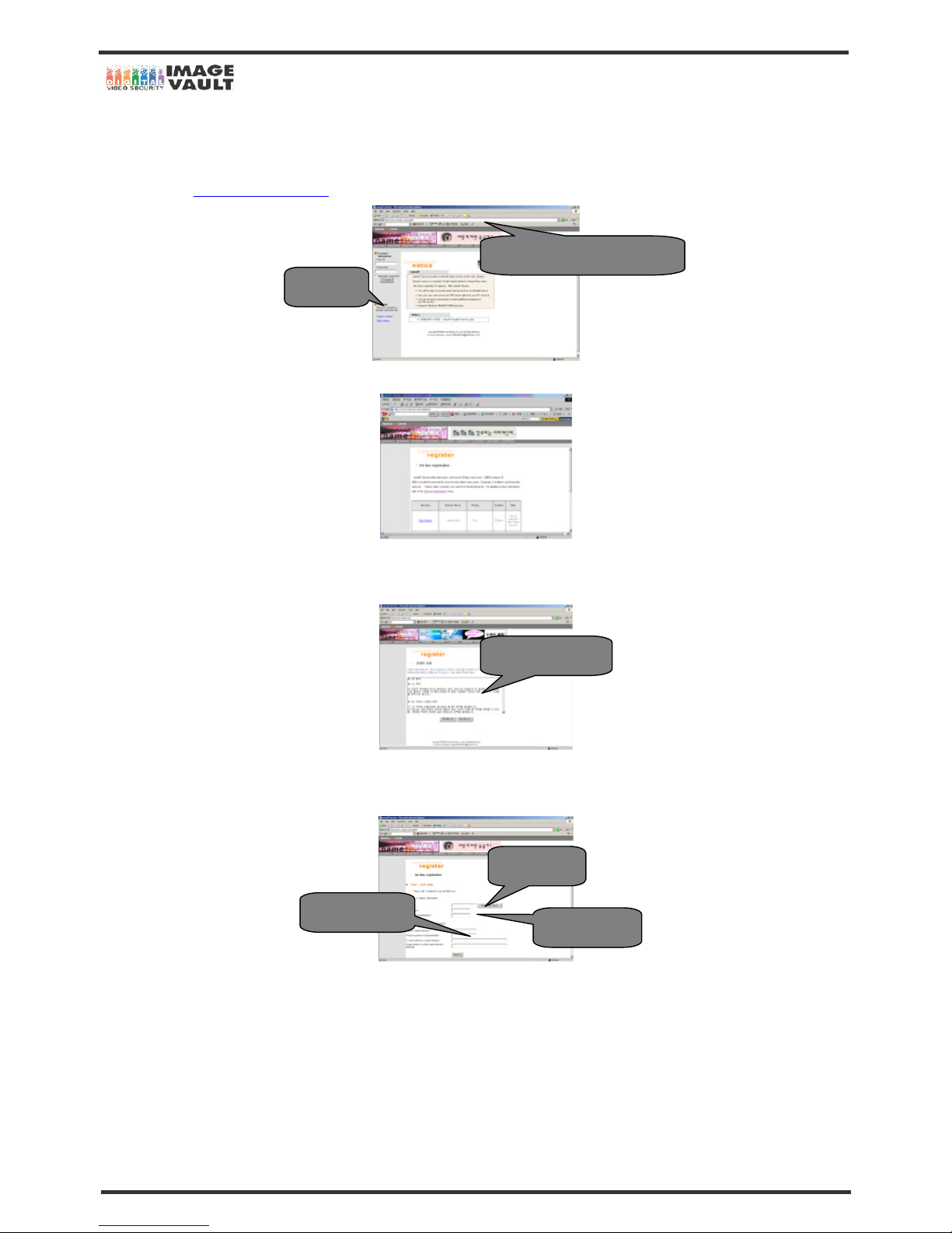
. Default page as below is as below. Click on ‘SIGN UP’ to continue.
2. Once you click on ‘SIGN UP’, you will see the same web page as below. Click on ‘FREE SERVICE’.
3. Once free service is signed up the, service will be done for 30 days without any charge. After 30 days, you can resign up the service.
Click ‘AGREE’ after reading the service agreement.
4. Once the service agreement is agreed by the user, the below page can be seen. Please fill in the registration form. Once entering the
User ID, please check whether it is being used or not. Type the password and fill in the details. When the form is filled in, click on ‘Next ’.
http://www.nameip.com/english/
‘SIGN UP’
Service Agreement
Put user ID
Put password
Personal Details
Page 42
Mobile DVR - Installation Manual
42/47
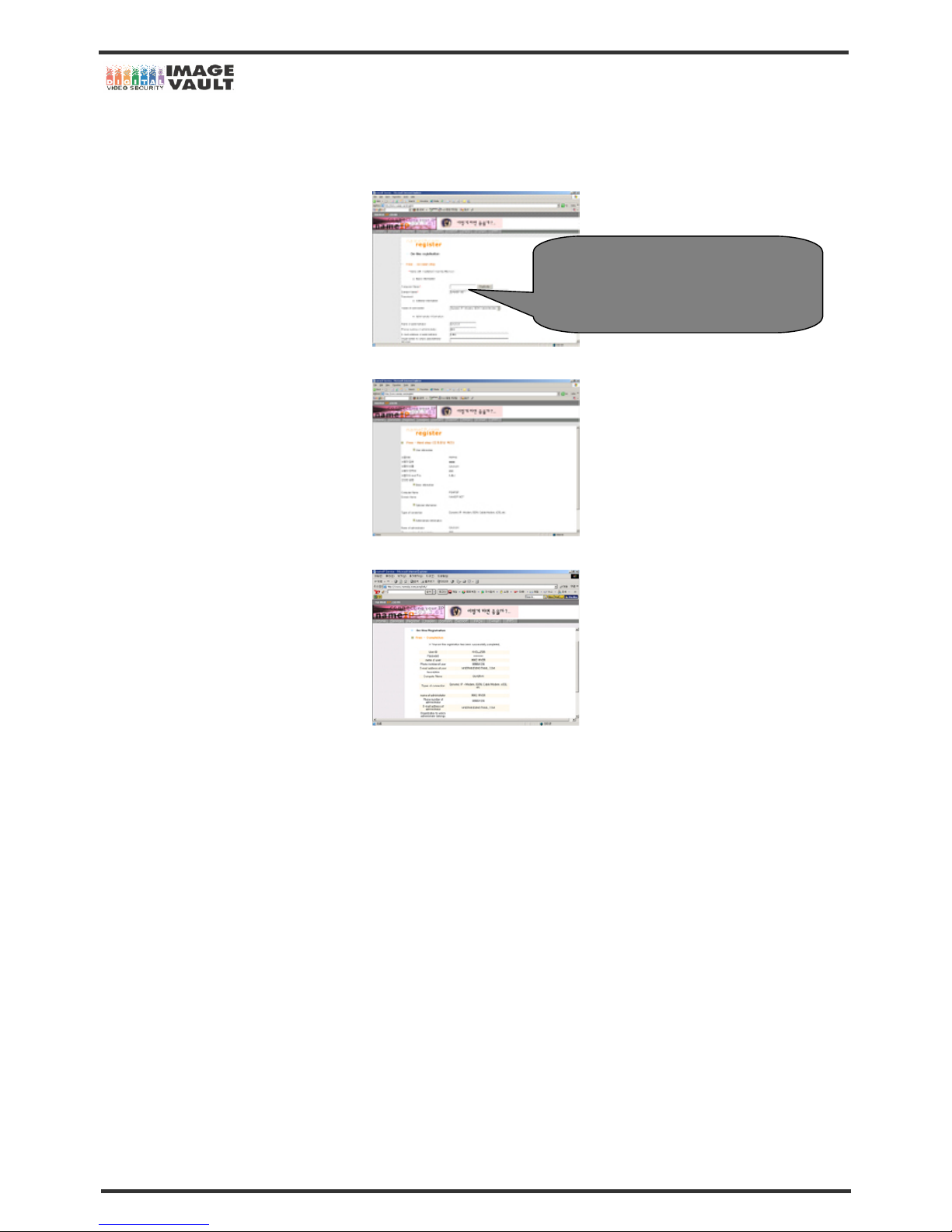
5. Once the registration form is filled, the below page can be seen. Next, set and type the name of computer. Once the name is typed, click
on ‘Duplicate’ to check whether it is in use or not. If dynamic IP is used, leave the option as it is and if you use Static IP, change the option to
‘Static IP – Leased line’. Check personal information and click on ‘Next’ to continue.
6. When all the information is properly done, then click on ‘Next’ and if not, go back to previous step and change the information.
7. The registration is now completed. Please print the page or make a note.
Name of Computer
(Type any name that is easy to remember. This
name will be used as IP address)
Page 43
Mobile DVR - Installation Manual
43/47
6.3 DVR Network Setup
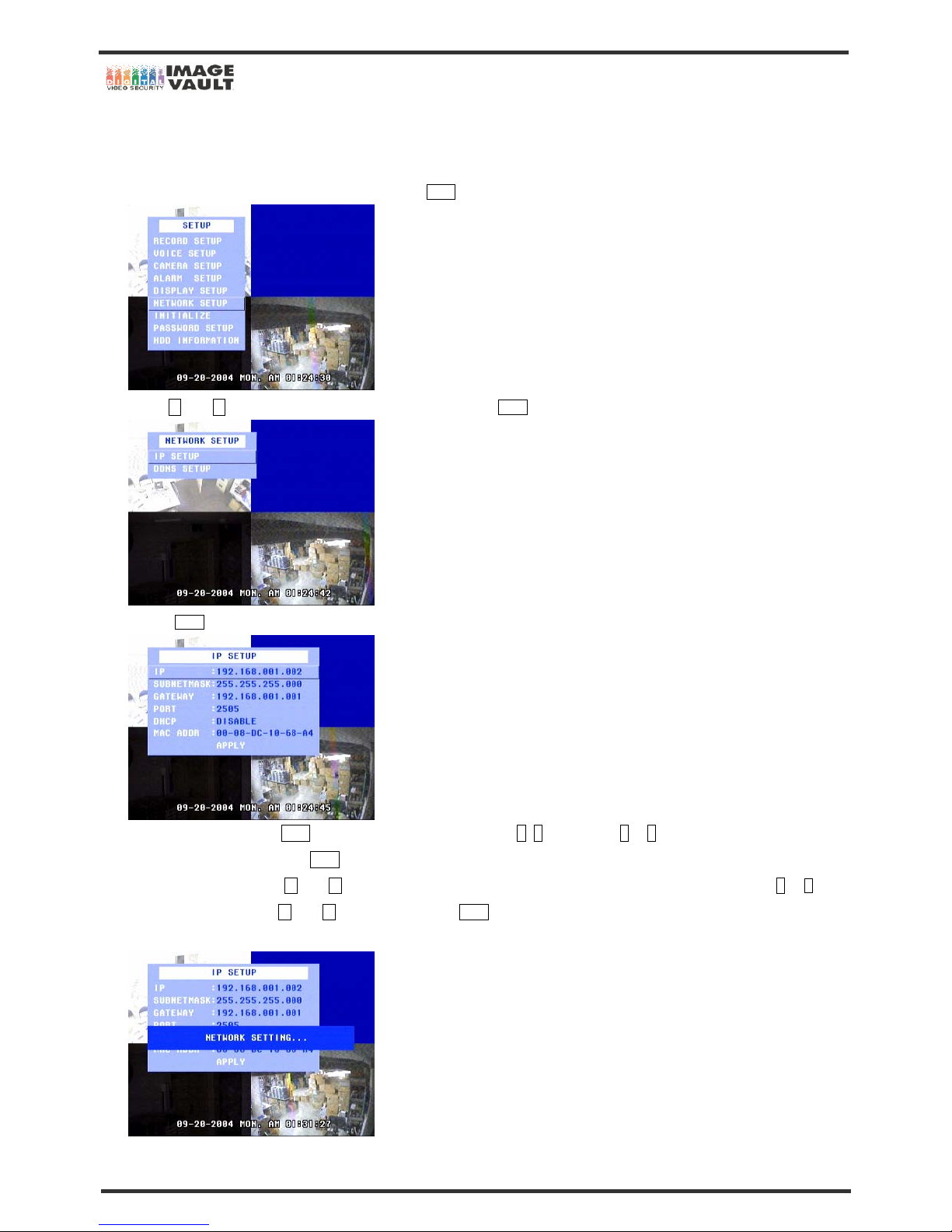
In order to view the images remotely, set IP and DDNS in DVR menu. Please follow the below instruction.
1. Press the MENU button to enter main menu and press Enter button to enter ‘SETUP’.
3. Use ∧ and ∨ button to select ‘NETWORK SETUP’ and press the Enter button to enter ‘NETWORK SETUP’.
4. Press Enter button to enter ‘IP SETUP’
5. If the IP is static IP, press Enter button and move the field by pressing <, > button. Press - or + button to change the number. After
putting the IP address, press the Enter button to save the changes.
If the IP is dynamic IP, use ∧ and ∨ button to select ‘DHCP’ and change the option to ‘DHCP: ENABLE’ by pressing - or + button.
Select ‘APPLY’ by pressing ∧ and ∨ button and press the Enter button to obtain IP address. When the DVR obtains the IP address,
make a note the IP address. It will be required for IP Share Router setting.
Page 44

Mobile DVR - Installation Manual
44/47
7. Change the port number. Select from 2500 to 2509 and any port number in the range. Press the Enter b utton to sa ve the chang e . P l ea s e
remember the IP and Port number. The information will be required to set the program.
8. Press Esc button to escape. If you did sign for DDNS, go back to ‘NETWORK SETUP’ by pressing Esc button. Then, press ∨ button
and press the Enter button to enter ‘DDNS SETUP’.
9. Put your ID and Password that are registered in nameip service registration. Press Enter button and use - or + button to change the
value. To move the cursor, press > and < buttons. Once you complete the entering, press the Enter button to save the changes.
10. Network setup of DVR is now finished. Press Esc button to escape. Follow the next chapter to set IP sharing router.
6.3.1 Information on IP setting
- IP (Internet Protocol), Subnet Mask, Gateway: IP address and a subnet mask must be given to DVR in order to communicate with i t over
network. DVR requires a Static IP address, a Dynamic IP address or domain name.
- DHCP (Dynamic Host Configuration Protocol): DHCP can be used to automatically assign IP addresses, to deliver TCP/IP stack
configuration parameters such as the subnet mask and gateway. Set ‘ENABLE’ to obtain IP, Subnet Mask and Gateway address
automatically.
- Mac Addr: On a local area network, the MAC (Media Access Control) is your computer's unique hardware number.
Page 45
Mobile DVR - Installation Manual
45/47
6.4 IP Sharing Router Setup
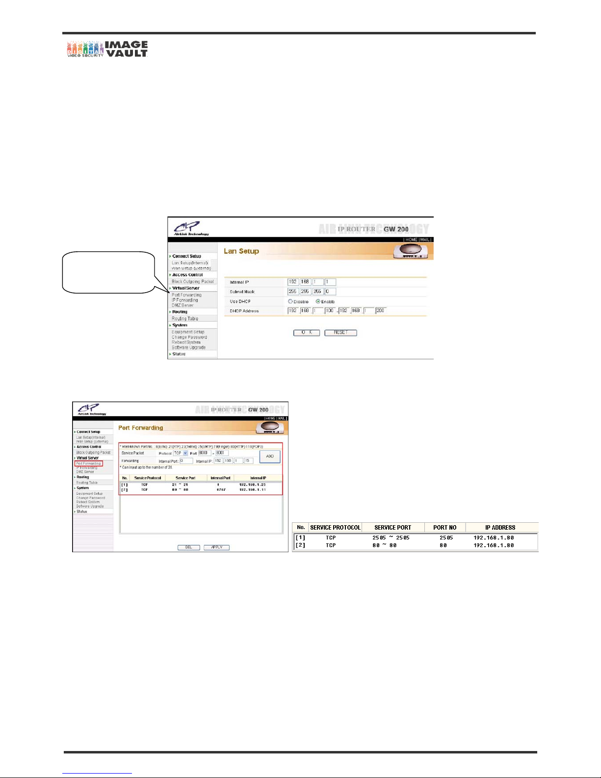
If the user uses IP Sharing Router, you will need to forward the PORT number in Virtual Server Setup in order to retrieve the images from
DVR. DVR uses Port no. 2500~2509 and Port no. 80 to transmit the images, so the user requires to forward Port to use remote viewing in
IP Sharing Router application.
1. Most of IP Sharing Router has own Port and IP setting web page. The user requires setting Port Forwarding in Virtual Server Setup in this
setting page. Below captured web page is setup page for ‘Anygate’ IP Sharing Router that our company uses. Please contact IP Sharing
Router’s company for more information or see the Router manual before continuing Router setup. Click on Port Forwarding Setup to
continue.
2. The user requires to adding new service in Port Forwarding. Put ‘80’ in Port number section and put IP address that you made a note in
DVR’s DDNS setup. Please do the same operation with port number that requires setting in DVR’s IP setup.
3. IP Sharing Router setup is now done. Please continue to set remote viewing program, DVR Manager.
Virtual Server Setup
Port Forwarding
Page 46
Mobile DVR - Installation Manual
46/47
6.5 DVR Manager Setup
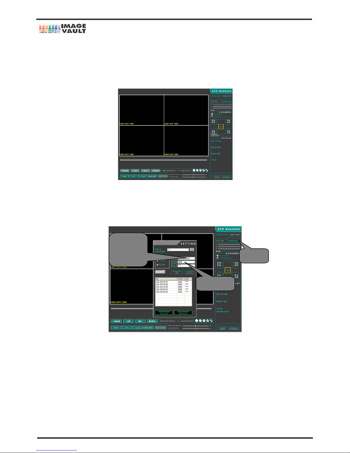
Please setup remote viewing program ‘DVR Manager’ to connect with your DVR from bundle CD title or your supplier’s website. Put Domain
Name or IP address in DVR Manager ‘SETTING’ menu. Please follow the instruction given below.
1. Run DVR Manager.
2. Click on the ‘SETTING’ icon on menu bar. Put Domain Name or IP address. Domain Name is the one that has been registered during
the DDNS registration. If the computer name has is entered as ‘DVR’ and domain name as ‘nameip.net’, then Domain Name will be
‘DVR.nameip.net’. (Please see the next page or refer to DDNS Sign Up chapter) And put the Port number that you set in DVR’s ‘IP
SETUP’ menu.,
3. DVR Manager setup is now done. Please read the attached DVR Manager manual for more information.
Setting
DDNS
Or
IP Address
Port Number
Page 47
Mobile DVR - Installation Manual
47/47
7. FAQ
Question Answer
DVR Power does not turn on.
- Ensure that DVR power cable is connected properly.
- Check the power voltage
Monitor shows nothing.
- Ensure that the power cords of DVR and monitor are connected properly.
- Check if the connection between Monitor and DVR is correct.
What if the DVR cannot detect HDD?
- Ensure that the Removable HDD Rack is locked.
- Even if you locked the rack and the DVR cannot find the HDD, please reinstall the HDD
and try again.
Monitor screen is shaky.
- Check if the connection between Monitor and DVR is correct.
- Check if you have a correct video mode.
- Check the camera connection.
Screen images of some channels are not shown
or resolution is not good.
- Check if camera is well connected to DVR
When camera lens is not clean or out of focus, the images can blur.
- You should adjust focus from installed camera. From the place in the back of DVR
where camera is connected, change the position of normal screen camera with abnormal
one.
Then, you should check the power cord or screen cable of the camera.
When the problem continues, contact the company which installed the camera.
If the normal camera in the first place changed into abnormal one, contact Call center.
Time shown on DVR is not correct.
- The DVR is manufactured standardizing time of South Korea, producing center.
Therefore time on DVR can be different from local time. In this case, you can adjust time
at Setup-System-Date and Time.
What is the password for the first time log-in when
using the DVR?
- The DVR do not have set-up Password for log-in. If you want to set up password, you
can do it at Main Menu of the DVR.
Let's say the HDD is nearly full. You want to take it
out, and put a new one. How do you do this? How
does the new HDD get the operating system?
- If the HDD is full and you want to replace it with new HDD, then just take the old one
out and put new one. And just turn on, simple as that. However, one thing that you have
to be careful with is to change the HDD to master mode.
Does the DVR have overwriting features?
- The DVR has overwriting feature and the default is to overwrite the past video. Please
go to RECORD SETUP to disable the overwriting feature.
 Loading...