

ImageStream PacketMate 1400 User Manual

004
Version: 2892
Copyright 2007-2010 ImageStream Internet Solutions, Inc., All rights Reserved.


Table of Contents
Router Manuals/004............................................................................................................................................1
PacketMate 1400 Router...................................................................................................................................3
Preface.....................................................................................................................................................3
Scope of this Manual........................................................................................................................3
Manual Organization........................................................................................................................3
Safety Information............................................................................................................................3
FCC and Canada Compliance..........................................................................................................5
Part 15 Compliance..........................................................................................................................5
Electromagnetic Compatibility.........................................................................................................5
La Compatibilité d? Eléctro-magnetique.........................................................................................5
Service Support and Training...........................................................................................................5
Chapter 1: Introduction and Specifications.............................................................................................6
Overview..........................................................................................................................................6
Specifications...................................................................................................................................7
Chapter 2: Installation and Setup............................................................................................................8
Overview..........................................................................................................................................8
Unpacking Instructions.....................................................................................................................8
Installation Procedures.....................................................................................................................9
Chapter 3: Operations Information.......................................................................................................12
Open the Chassis............................................................................................................................13
CPU Location.................................................................................................................................13
RAM Slot Location........................................................................................................................13
Flash Storage Location...................................................................................................................14
Battery Location.............................................................................................................................14
Power Supply Location..................................................................................................................14
Hard Drive Location.......................................................................................................................15
Software..........................................................................................................................................16
Chapter 4: BIOS Settings......................................................................................................................16
Start up...........................................................................................................................................16
Reseting BIOS................................................................................................................................17
Main Menu.....................................................................................................................................17
Advanced Menu.............................................................................................................................18
PCI/PnP..........................................................................................................................................29
BOOT.............................................................................................................................................30
Security...........................................................................................................................................33
Chipset............................................................................................................................................34
Exit.................................................................................................................................................36
Copyright..............................................................................................................................................37
Trademarks...........................................................................................................................................37
Related Publications.............................................................................................................................37
i

ii

Router Manuals/004
Router Manuals/004 1

004
2 Router Manuals/004

PacketMate 1400 Router
Preface
Scope of this Manual
This manual describes how to install and operate the PacketMate 1400 Router. The information contained in
this manual has been carefully checked and is believed to be entirely reliable. However, as General
DataComm improves the reliability, function, and design of their products, it is possible that information may
not be current. Contact General DataComm if you require updated information for this or other General
DataComm products.
General DataComm, Inc.
Network Access Division
Technical Publications Department
Park Road Extension
Middlebury, Connecticut, USA 06762-1299
Tel: 1 203 758 1811 Toll Free: 1 800 794 8246
Manual Organization
This manual describes how to operate and configure your PacketMate 1400 Router system to meet various
operating requirements. It is divided into four chapters, with each chapter addressing the basic concept and
operation of this system.
Chapter 1: Introduction and Specifications. This section an overview of the PacketMate 1400 Route.
Chapter 2: Installation and Setup. This chapter unpacking instructions and installation procedures.
Chapter 3: Operation Information. This section provides illustrations and information on the system
architecture and how to optimize its performance.
Chapter 4: This section describes BIOS settings.
Safety Information
This manual should be read in its entirety and all procedures completely understood before installing or
operating the unit. The notes that appear throughout this manual must be read prior to any installation or
operating procedure. Examples of notes used in this manual are shown below.
Note
Indicates a note. It is something you should be particularly aware of; something not readily apparent.
A note is typically used as a suggestion.
Important
Indicates an emphasized note. It is something you should be particularly aware of; something not
readily apparent. Important is typically used to prevent equipment damage.
PacketMate 1400 Router 3
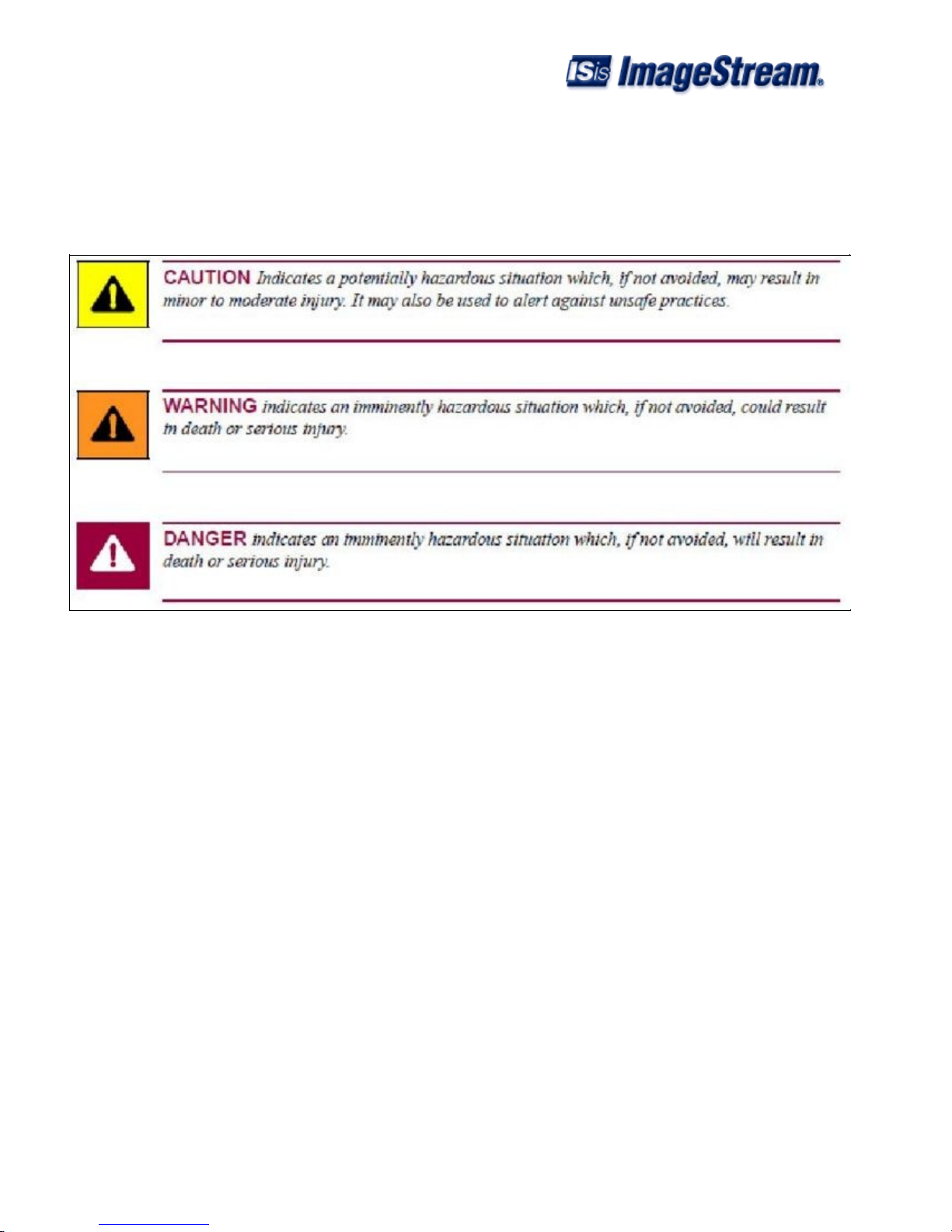
The CAUTION, WARNING, and DANGER statements that appear throughout this manual are intended to
provide critical information for the safety of both the service engineer and operator. These statements also
enhance equipment reliability. The following definitions and symbols for CAUTION, WARNING, and
DANGER as they are used comply with ANSI Z535.2, American National Standard for Environmental and
Facility Safety Signs, and ANSI Z535.4, Product Safety Signs and Labels, issued by the American National
Standards Institute.
Safety Guidelines
Always use the following guidelines when unsafe conditions exist or when potentially hazardous voltages are
present:
Always use caution and common sense.•
Repairs must be performed by qualified service personnel only.•
To reduce the risk of electrical shock, do not operate equipment with the cover removed.•
Never install telephone jacks in a wet location unless the jack is designed for that location.•
Never touch uninsulated wires or terminals unless the line is disconnected at the network interface.•
Antistatic Precautions
Electrostatic discharge (ESD) results from the buildup of static electricity and can cause computer
components to fail. Electrostatic discharge occurs when a person whose body contains a static buildup touches
a computer component. This product may contain static-sensitive devices that are easily damaged. Proper
handling, grounding and precautionary ESD measures are essential when installing parts or cards. Keep parts
and cards in antistatic packaging when not in use or during transport. If possible, use antistatic floorpads and
workbench pads.
004
4 Safety Information

When handling components, always use an antistatic wrist strap connected to a grounded equipment frame or
chassis. If a wrist strap is not available, periodically touch an unpainted metal surface on the equipment.
Never use a conductive tool, like a screwdriver or a paper clip, to set switches.
FCC and Canada Compliance
Refer to the individual product card manuals for Compliance information.
Part 15 Compliance
This device complies with Part 15 of the FCC rules. Operation is subject to the following two conditions: 1.
This device may not cause harmful interference and 2. This device must accept any interference received,
including interference that may cause undesired operation.
Electromagnetic Compatibility
This Class A digital apparatus complies with Canadian ICES-003.
La Compatibilité d? Eléctro-magnetique
Cet appareil numerique de la classe A est conforme a la norme NMB-003 du Canada.
Service Support and Training
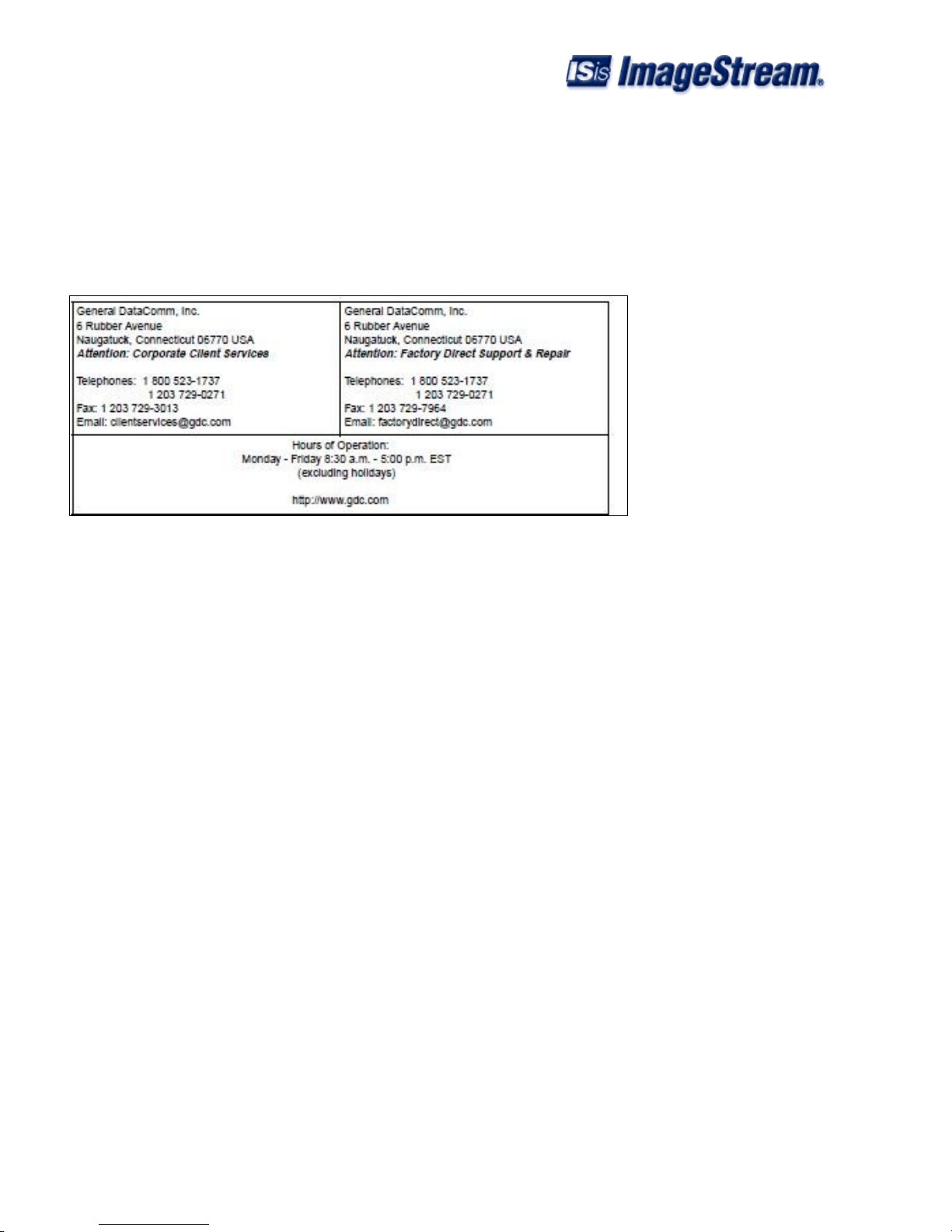
General DataComm offers two comprehensive customer support organizations dedicated to pre-and post-sale
support services and training for GDC products. Corporate Client Services and Factory-Direct Support &
Repair assist customers throughout the world in the installation, management, maintenance and repair of GDC
equipment. Located at GDC?s corporate facility in Naugatuck,Connecticut USA, these customer support
organizations work to ensure that customers get maximum return on their investment through cost-effective
and timely product support.
Corporate Client Services
Corporate Client Services is a technical support and services group that is available to GDC customers
throughout the world for network service and support of their GDC products. Customers get the reliable
support and training required for installation, management and maintenance of GDC equipment in their global
data communication networks. Training courses are available at GDC corporate headquarters in Naugatuck,
Connecticut, as well as at customer sites.
Factory Direct Support & Repair
GDC provides regular and warranty repair services through Factory Direct Support & Repair at its U.S.
headquarters in Naugatuck, Connecticut. This customer support organization repairs and refurbishes GDC
products, backed by the same engineering, documentation and support staff used to build and test the original
product. Every product received for repair at Factory Direct Support & Repair is processed using the test
004
FCC and Canada Compliance 5
fixtures and procedures specifically designed to confirm the functionality of all features and configurations
available in the product.
As part of GDC?s Factory Direct program, all product repairs incorporate the most recent changes and
enhancements from GDC Engineering departments, assuring optimal performance when the customer puts the
product back into service. Only GDC?s Factory Direct Support & Repair can provide this added value.
Contact Information
Chapter 1: Introduction and Specifications
Overview
The PacketMate 1400 Router is GDC's high-performance midrange router for applications that require
wire-speed performance over T1/E1, DS3/E3, OC3/STM1, OC12/STM4 and gigabit ethernet connections.
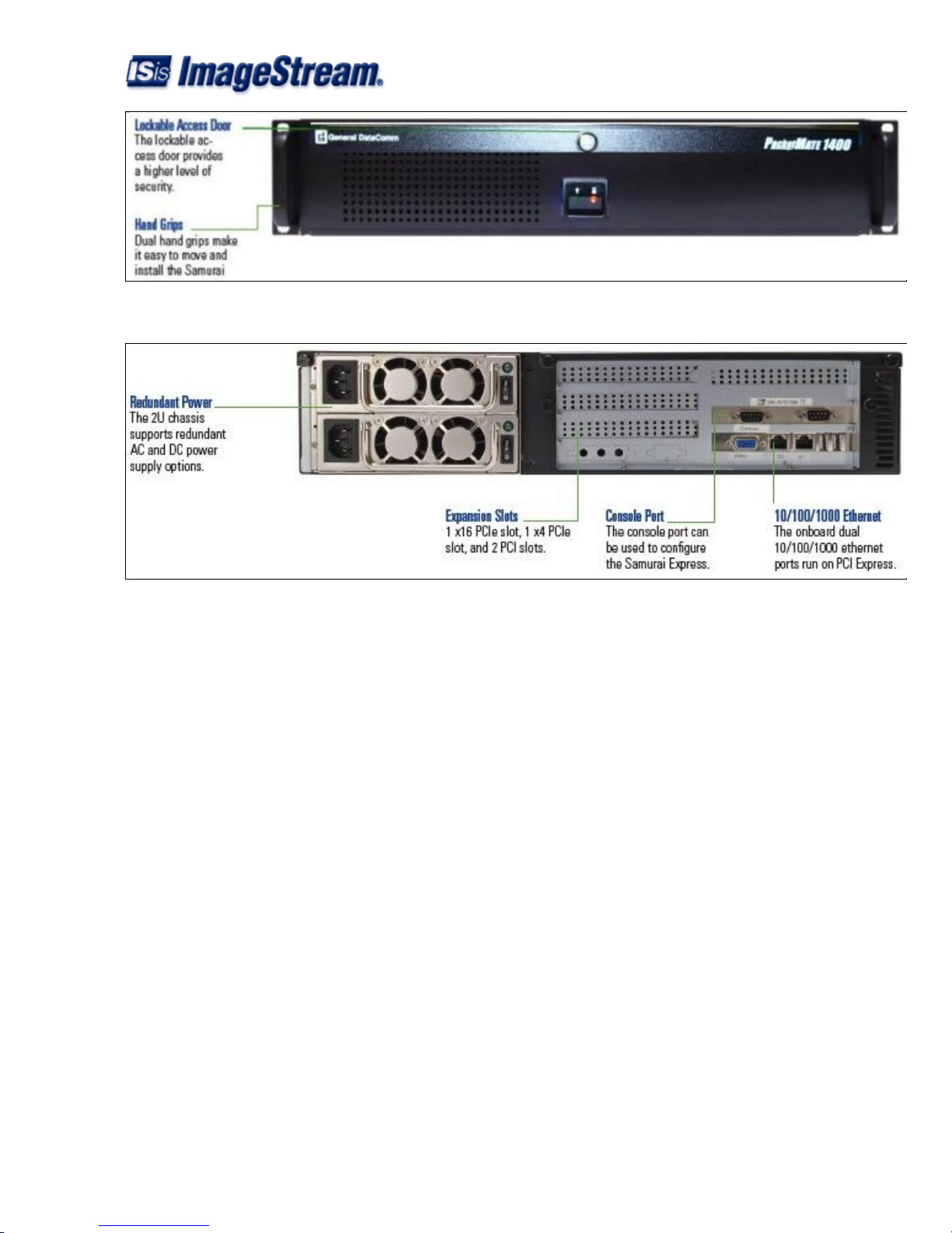
The PacketMate 1400 Router supports options for AC or DC power and redundant AC or DC power. It
includes an easy-to-service 19-inch 2U rackmount chassis with locking access door, removable processor
card, special high-performance memory, PCI Express backplane, and onboard dual 10/100/1000 ethernet
ports. The PacketMate 1400 Router also uses flash storage with no moving parts to maximize reliability.
The PCI expansion slots accept Industrial Series network cards with Ethernet, sync serial, T1/E1, DS3/E3,
analog FXO/FXS, BRI, PRI, and 56K dial-up interfaces. With these add-on cards, the PacketMate can connect
different data and voice networks using a wide range of communications standards.
The base PacketMate 1400 Router is guaranteed to route two DS3/E3 circuits at wire speed, 16 T1/E1 circuits
at wire speed, or more than 100 Mbps full duplex with 64-byte packets over Ethernet. With the optional CPU
upgrade, the PacketMate can deliver up to 70% higher Ethernet throughput with VoIP traffic, and over 6 Gbps
aggregate or 3 Gbps full duplex with large packets.
004
6 Service Support and Training
Specifications
Hardware
Chassis: Steel 2U 19" rackmount
Processor: Intel LGA 775 Quad Core
Memory: 512 MB DDR2
Storage: Fixed flash disk
Network Ports: Dual 10/100/1000 Ethernet on PCI Express
Management Port: Serial console
USB: (2) USB 2.0 ports
Expansion Interface: 2) 32-bit 33 MHz PCI slots
(1) x16 PCI Express Slot
(1) x4 PCI Express Slot
Power Supply
Design: Switch-selectable voltage
AC Mains Voltage: 115/230
AC Mains Frequency: 50 to 60 Hz
Power Output: 350 W
004
Overview 7

Dimensions
Height: 3.5 inches (89 mm)
Width: 19 inches (483 mm)
Depth: 17.4 inches (442 mm)
Weight: 32.3 lbs. (14.7 kg)
Options
Memory: 512 MB, 1 GB, 2 GB or 4 GB DDR2 800/667 DIMM
LAN Cards: 1, 2, and 4-port PCIx and PCIe Ethernet
WAN Cards: 1 and 2-port DS3/E3 or HSSI
1-port OC3
1-port DS3 or E3
1, 2, 4 and 8-port serial, T1 or E1
1, 2, 4 and 8 port sync serial
1-port basic rate ISDN (BRI)
1-port 56 K modem
Voice Cards: 1 to 4-port FXO/FXS
1, 2 & 4-port ISDN BRI
1, 2 & 4-port T1/E1 PRI
Hard Drive Option: 80 GB
Power Supply Option: -48 V DC
Dual input redundant AC or DC
Chapter 2: Installation and Setup
Overview
The PacketMate 1400 Router is pre-assembled, tested, and ready for use. This chapter provides procedures for
installing the unit, power connections, the product cards, and finally, making system connections. If this is
your first installation, you should be familiar with Chapter 1, Introduction and Specifications , for a better
understanding of the features and use of the unit in your network.
Unpacking Instructions
The unit components are shipped in shock-absorbent packing within a corrugated box. Remove each
component from the box and perform a thorough visual inspection. If damage has occurred to any component,
contact the shipper immediately. All damaged components must be retained until an inspection by the shipper
has been completed. If it is necessary to re-package and return the unit, use the original packing materials and
004
8 Specifications

box.
Installation Procedures
Unpacking The Router
This section describes the installation of the PacketMate 1400 Router and it?s standard equipment. It does not
describe the configuration or other details of specific plug-in product cards UAS family products that it
houses; for that information, refer to Related Publications on page ii.
External devices are connected to the router through standard connectors ports which are located on
the front panel of the router and the ports on optional cards located on the rear panel.
•
Place the unit in a ventilated area where the ambient temperature does not exceed 104oF (40oC).•
Do not install the unit directly above equipment that generates a large amount of heat (such as power
supplies).
•
AC Power Connection
Before making connections, determine whether the unit can be powered from the same AC circuit as the
Business Equipment it will be communicating with. Having the unit and the Business Equipment on the same
AC circuit prevents large circulating currents caused by differences in ground potential.
Note
If you cannot determine whether both devices are on the same circuit, verify that the potential
difference between the grounding circuits of the respective power outlets is no more than 0.25V rms.
To connect the unit to power, perform the following steps:
Attach the power cord to the rear panel IEC connector and to a wall receptacle or surge protector
device that supplies the required AC power.
1.
Turn the power switch to the ON (1) position.2.
Verify that the front panel power LED illuminates to indicate the PacketMate is supplying power to
the router.
3.
Booting the PacketMate 1400 Router
When you start up the router, it carries out the following functions during the booting process:
Self-diagnostics are performed. The results are displayed to the console port.1.
A selection dialog is displayed that allows the router to be booted into its standard operating mode,
failsafe, or the memory test module.
2.
If no boot option is chosen, Enterprise Linux will load in normal operating mode.3.
The user configuration is loaded from nonvolatile flash memory.4.
Logging In for the First Time
004
Unpacking Instructions 9
 Loading...