


MAINTENANCE / INSTALL & TROUBLESHOOT GUIDE FOR MVDS
RTMS Detector (MVDS):
The non-intrusive radar-based RTMS® (Remote Traffic Microwave Sensor) G4™ is an advanced
sensor for the detection and measurement of traffic on roadways. The RTMS G4 is small,
roadside pole-mounted radar operating in the microwave band. Simultaneously, the sensor
provides per-lane presence as well as volume, occupancy, speed and classification information
in up to 12 user-defined detection zones. Output information is provided to existing
controllers via contact closure and to other computing systems by serial or IP communication
port or by an optional radio modem. A single RTMS can replace multiple inductive loop
detectors and the attendant controller

WORK ORDERS:
As Operators perform daily device checks, issues are entered in MOMS. Field Technicians
retrieve the time stamped work orders and are required to acknowledge within one (1) hour
of input. The repair is required to be completed within Forty eight (48) hours of input, per our
contract with TransCore. Technician will log on to Moms, proceed to Open Work Orders.
Site Cabinet
Before troubleshooting, you will need to adjust the adapter settings in your
computer, to attach to the cabinet network device in that zone.

At cabinet:
Connect Ethernet cable to Ethernet switch
Click internet access icon on tool bar to connect to server
Right click, open network sharing center
Change Adapter settings on left
Click local area network
Click Internet Protocol version 4( TCP/IPv4)
Click Use the following IP address
Enter your computers IP address
Use Device Checklist to get info ( IP addresses, and Zones)
Change third digit in IP address and Default gateway, to match zone
Example: My IP address: (10.164.0.123)
Subnet mask: (255.255.255.0) “Always use same”
Default Gateway: (10.164.0.1)
Click ok / Ready to access device for the zone needed
Open G4 Software:
Call TMC to take MVDS out of service (to allow TCP/IP connection)
Click on communication
Click pc serial, choose PC TCP/IP from drop down menu
Enter IP address of terminal server, for the site (see device checklist)
Enter remote port # (see device checklist) of problem detector
Click OK
Click single RTMS to access device
Click on Normal. The Device is ready to calibrate

Next step is to calibrate the MVDS:
Click on Wizard Setup, let run until all lanes are detected/ once all lanes are
detected Wizard will close automatically (add 1 minute if needed)
Click Manual Settings
Click Zones
Number, and adjust lane direction as needed per screen instructions
Click OK
Click Exit once
Click Speed Calibration / enter speed limit for location of mvds
Click Start / let run until all lanes reach 100%/ Exit
Exit & Click calibration. Enter speed limit for the area in each lane shown
(set inner lanes a few mhp faster than outer lanes)
Click Start / let run till completed (add time if still needed)
Exit & Click Statistics, check box to note calibrated speeds, then Exit
Click Calibration again, choose Manual Settings, adjust lane speeds one at a
time using up and down arrows for lane change, and left and right arrows for
speed change
Exit & Click Statistics again / check box to show traffic for current speeds,
if speeds look good, then exit, If not, repeat steps above.
Click Manual Settings again
Click Data, change from Normal to Polled status (allows Sunguide to read)
Click Exit, then Exit Program, to complete process
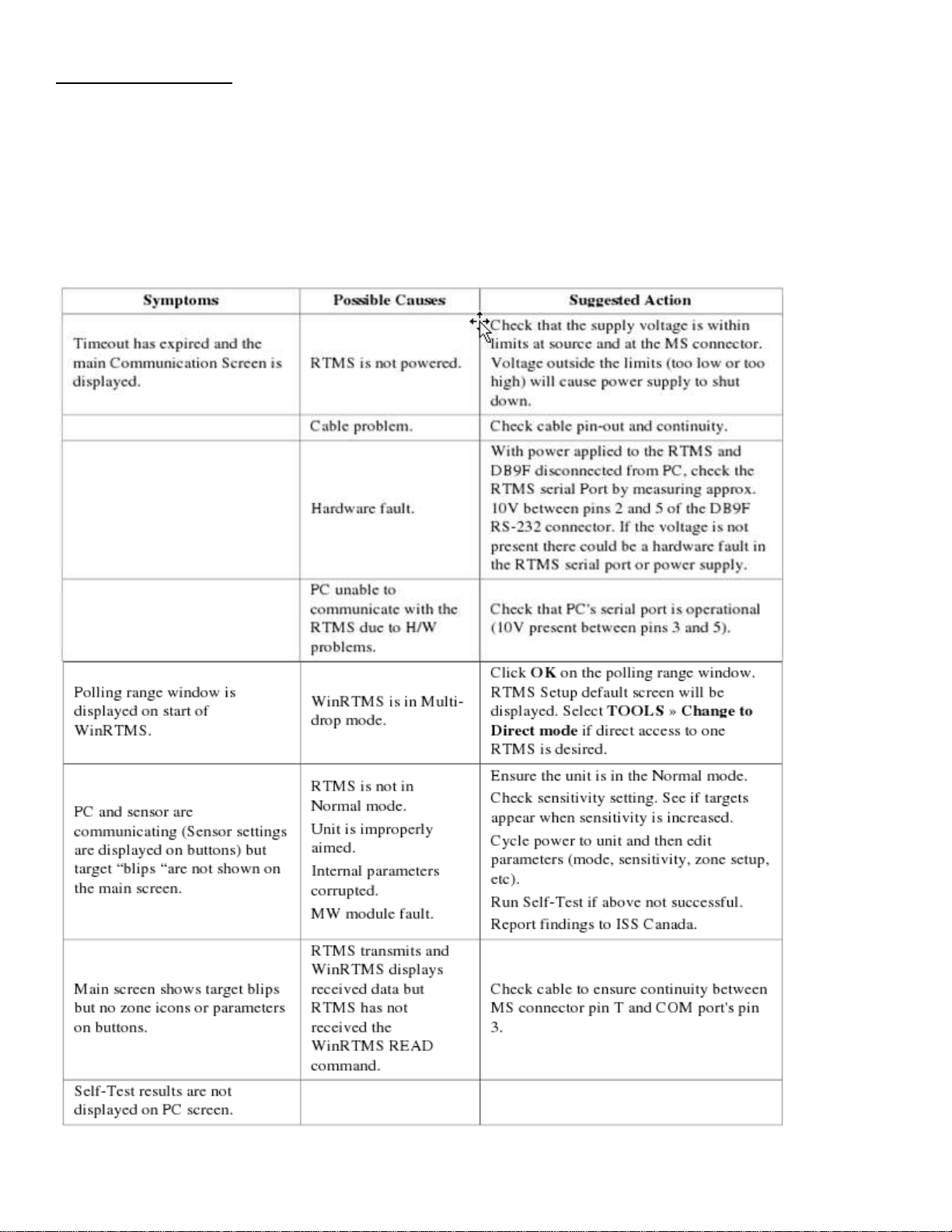
TROUBLESHOOT:
Field troubleshooting of the RTMS consists mainly of ensuring that the unit is powered and
Communicating. Communication with the sensor in Normal mode is confirmed by presence of
The moving Vehicles and menu button, and by the flashing of the indicator in the lower right
Corner of the screen, denoting data transmission activity. The table below outlines symptoms
And suggested action in troubleshooting power and communication problems:

RTMS Detector (MVDS) Mile Marker (MM) Locations:
I-10
.1 - (EB/WB) 21.4 - (WBM)
.6 - (EB/WB) 12.2 - (EB/WB) 22.1 - (EB/WB)
1.0 - (EB/WB) 12.7 - (EB/WB) 22.6 - (EB/WB)
1.6 - (EB/WB) 13.2 - (EB/WB) 23.1 - (WB/EB)
2.2 - (EB/WB) 13.7 - (EB/WB) 23.5 - (EB/WB)
2.7 - (EB/WB) 14.2 - (EB/WB) 24.2 - (EB/WB)
3.2 - (EB/WB) 14.9 - (EB/WB) 24.7 - (EB/WB)
3.7 - (EB/WB) 15.4 - (EB/WB) 25.2 - (EB/WB)
4.3 - (EB/WB) 15.7 - (EB/WB) 25.6 - (EBM)
4.8 - (EB/WB) 16.3 - (EBM) 25.6 - (WBM)
5.3 - (EBM) 16.3 - (WBM) 26.1 - (EB/WB)
5.8 - (EB/WB) 16.6 - (WB) 26.6 - (WB/EB)
6.3 - (EB/WB) 17.3 - (EB) 27.5 - (EB/WB)
6.8 - (EBM) 17.3 - (WB) 28.3 - (EB/WB)
6.8 - (WBM) 17.9 - (EB) 28.7 - (EB/WB)
7.5 - (EB/WB) 17.9 - (WB) 29.0 - (EB/WB)
8.1 - (EB/WB) 18.6 - (EB) 29.4 - (EB/WB)
8.6 - (EB/WB) 18.6 - (WB) 29.9 - (EB/WB)
9.2 - (EB/WB) 18.9 - (EB) 30.5 - (EB/WB)
10.0 - (EB) 18.9 - (WB) 30.9 - (EBM)
10.0 - (WB) 19.7 - (WB/EB) 30.9 - (WBM)
10.5 - (WB/EB) 20.4 - (EB/WB) 31.5 - (EB/WB)
11.1 - (EB/WB) 20.9 - (EB/WB) 32.0 - (WB/EB)
11.4 - (EB/WB) 21.4 - (EBM) 32.6 - (EB/WB)

I-110
.4 - (NBM) 2.7 - (SB/NB)
.4 - (SBM) 3.1 - (SB/NB)
.9 - (NBM) 3.6 - (SB/NB)
.9 - (SBM) 4.1 - (SB/NB)
1.3 - (NBM) 4.5 - (NB/SB)
1.3 - (SBM) 5.0 - (NB/SB)
1.9 - (NB/SB) 5.6 - (NB/SB)
2.3 - (NB/SB)
Installing the Comtrol Terminal Server
Click lower right (Symantec Endpoint Protection) antivirus Icon, turn off Proactive & Network Threat
Protection. Click options, and disable each.
Connect an ethernet cable from Laptop to Terminal Server.
Click on Portvision desktop icon to open. Click (scan for devices) Terminal Server will appear. Click on the
newly found device. The Terminal Server will open and show its default IP address.
Change the default IP address to the proper IP for your location. (See device IP sheet)
Enter the new IP address, subnet, and gateway for your location. Click Apply, then Reboot and exit.
Reopen Portvision on desktop. Click (scan for devices). Click on the device found, and the Terminal Server will
open with the new IP address. Can now access the Terminal Server for programming.

 Loading...