

Image 10.6Qi IETL15910 User Manual
USER'S MANUAL
®
Serial Number Decal
Model No. IETL15910
Serial No.
CAUTION
Read all precautions and instructions in this manual before using
this equipment. Save this manual
for future reference.
Write the serial number in the space
above for future reference.
Class HC Fitness Product
www.imagefitness.com
Visit our website at
Part No. 173881 R0601A Printed in USA © 2001 ICON Health & Fitness, Inc.
IMAGE is a registered trademark of ICON Health & Fitness, Inc.
QUESTIONS?
As a manufacturer, we are
committed to providing
complete customer satisfaction.
If you have questions, or if
there are missing parts, we will
guarantee complete satisfaction
through our Customer Service
Department.
Please CALL:
Or WRITE:
ICON Health & Fitness Ltd.
Unit 4
Revie Road Industrial Estate
Revie Road
Beeston
Leeds, LS118JG
UK
email: csuk@iconeurope.com
08457-089 009
HOW TO ORDER REPLACEMENT PARTS
To order replacement parts, contact the ICON Health & Fitness Ltd. office, or write:
ICON Health & Fitness Ltd.
Unit 4
Revie Road Industrial Estate
Revie Road
Beeston
Leeds, LS118JG
UK
Tel: Country Code:
Outside the UK: 0 (044) 113 387 7133
Fax: 0 (044) 113-387 7125
When ordering parts, please be prepared to give the following information:
• The MODEL NUMBER OF THE PRODUCT (IETL15910)
• The NAME OF THE PRODUCT (IMAGE®10.6Qi treadmill)
• The SERIAL NUMBER OF THE PRODUCT (see the front cover of this manual)
• The KEY NUMBER OF THE PART(S) (see the PART LIST on pages 30 and 31 and the EXPLODED DRAWING
attached in the centre of this manual)
• The DESCRIPTION OF THE PART(S) (see the PART LIST on pages 30 and 31 and the EXPLODED DRAWING
attached in the centre of this manual).
08457-089 009

IMPORTANT PRECAUTIONS . . . . . . . . . . . . . . . . . . . . . . . . . . . . . . . . . . . . . . . . . . . . . . . . . . . . . . . . . . . . . . . . .2
BEFORE YOU BEGIN . . . . . . . . . . . . . . . . . . . . . . . . . . . . . . . . . . . . . . . . . . . . . . . . . . . . . . . . . . . . . . . . . . . . . . .4
ASSEMBLY . . . . . . . . . . . . . . . . . . . . . . . . . . . . . . . . . . . . . . . . . . . . . . . . . . . . . . . . . . . . . . . . . . . . . . . . . . . . . . .5
HOW TO USE THE HEART RATE MONITOR . . . . . . . . . . . . . . . . . . . . . . . . . . . . . . . . . . . . . . . . . . . . . . . . . . . .6
OPERATION AND ADJUSTMENT . . . . . . . . . . . . . . . . . . . . . . . . . . . . . . . . . . . . . . . . . . . . . . . . . . . . . . . . . . . . .7
HOW TO FOLD AND MOVE THE TREADMILL . . . . . . . . . . . . . . . . . . . . . . . . . . . . . . . . . . . . . . . . . . . . . . . . . .24
TROUBLE-SHOOTING . . . . . . . . . . . . . . . . . . . . . . . . . . . . . . . . . . . . . . . . . . . . . . . . . . . . . . . . . . . . . . . . . . . . .25
CONDITIONING GUIDELINES . . . . . . . . . . . . . . . . . . . . . . . . . . . . . . . . . . . . . . . . . . . . . . . . . . . . . . . . . . . . . . .28
PART LIST . . . . . . . . . . . . . . . . . . . . . . . . . . . . . . . . . . . . . . . . . . . . . . . . . . . . . . . . . . . . . . . . . . . . . . . . . . . . . . .30
HOW TO ORDER REPLACEMENT PARTS . . . . . . . . . . . . . . . . . . . . . . . . . . . . . . . . . . . . . . . . . . . . . .Back Cover
Note: An EXPLODED DRAWING is attached in the centre of this manual.
2
31
1. It is the responsibility of the owner to ensure
that all users of this treadmill are adequately
informed of all warnings and precautions.
2. Use the treadmill only as described in this
manual.
3. Place the treadmill on a level surface, with two
meters (8 ft) of clearance behind it. Do not
place the treadmill on any surface that blocks
air openings. To protect the floor or carpet
from damage, place a mat under the treadmill.
4. Keep the treadmill indoors, away from mois-
ture and dust. Do not put the treadmill in a
garage or covered patio, or near water.
5. Do not operate the treadmill where aerosol
products are used or where oxygen is being
administered.
6. When choosing a location for the treadmill,
make sure that the location and position permit access to a plug.
7. Keep children under the age of 12 and pets
away from the treadmill at all times.
8. The treadmill should not be used by persons
weighing more than 136 kgs (300 lbs).
9. Never allow more than one person on the
treadmill at a time.
10.Wear appropriate exercise clothing when
using the treadmill. Do not wear loose clothing that could become caught in the treadmill.
Athletic support clothes are recommended for
both men and women. Always wear athletic
shoes. Never use the treadmill with bare feet,
wearing only stockings, or in sandals.
11. When connecting the power cord (see page 7),
plug the power cord into an earthed circuit.
When replacing the fuse, an ASTA approved
BS1362 type should be fitted to the fuse carrier. A 13 amp fuse should be used. No other
appliance should be on the same circuit.
12. If an extension cord is needed, use only a 3conductor, 1mm2(14 gauge) cord that is no
longer than 1,5 meters.
13.Keep the power cord and the surge suppressor away from heated surfaces.
14.Never move the walking belt whilst the power
is turned off. Do not operate the treadmill if
the power cord or plug is damaged, or if the
treadmill is not working properly. (See
BEFORE YOU BEGIN on page 4 if the treadmill is not working properly.)
15.Never start the treadmill whilst you are standing on the walking belt. Always hold the
handrails whilst using the treadmill.
16.The treadmill is capable of high speeds.
Adjust the speed in small increments to avoid
sudden jumps in speed.
WARNING:
To reduce the risk of burns, fire, electric shock, or injury to persons, read the
following important precautions and information before operating the treadmill.
IMPORTANT PRECAUTIONS
T ABLE OF CONTENTS
Key No. Qty. Description Key No. Qty. Description
101 1 Circuit Breaker
102 1 Power Cord Set
103 1 Receptacle
104 2 Warning Decal
105 1 Chest Pulse Sensor
106 1 Jack
107 1 iFIT.com Audio Cable
108 1 Filter
109 2 2-pound Weight
110 4 Console Screw (short)
111 1 6” Audio Wire
112 1 Tension Washer
113 1 Tension Bolt
114 2 Motor Mounting Bushing
115 4 Front Isolator/Spacer Cap
116 2 Leaf Spring
117 1 Cushion Adjustment Rod
118 1 Left Cushion Adj. Rack
119 1 Right Cushion Adj. Rack
120 2 Cushion Adj. Gear
121 1 Cushion Adj. Knob
122 1 Splitter
123 4 Gear Screw
124 4 Leaf Spring Nut
125 4 Leaf Spring Bolt
126 2 Leaf Spring Spacer Bolt
127 2 Outlet Bracket Star Washer
128 2 Leaf Spring Star Washer
129 4 Push Nut
130 2 Leaf Spring Spacer
131 1 Idler Pulley Screw
132 1 Motor Controller Wire
133 4 Front Wheel Washer
134 1 Cushion Knob Washer
135 2 Front Walking Platform Screw
136 1 2 1/2” x 5 1/2” Plate
137 1 Bearing
138 1 Grounding Screw
139 1 Grounding Nut
140 1 Grounding Washer
# 1 8” White Wire, 2F
# 1 14” White Wire, 2 F
# 1 4” Blue Wire, 2 F
# 1 10” Blue Wire, 2F
# 1 14” Blue Wire, 2F
# 1 14” Black Wire, M/F
# 1 8” Black Wire, 2 F
# 1 4” Black Wire, 2 F
# 1 8” Green Wire, F/Ring
# 1 12” Green Wire, F/Ring
# 1 User’s Manual
* Includes all parts shown in the box
# These parts are not illustrated

30
3
Note: To identify the parts listed below, refer to the EXPLODED DRAWING attached in the centre of this manual.
P ART LIST—Model No. IETL15910 R0601A
Key No. Qty. Description Key No. Qty. Description
1 2 Foot Rail Insert
2 1 Right Foot Rail
3* 1 Idler Assembly
4 2 Isolator
5 1 Catch
6 1 Platform
7 2 Controller Screw
8 1 Walking Belt
9 2 Frame Pivot Bolt
10 1 Latch Assembly
11 1 Front Wheel/Pulley
12 1 Magnet
13 7 Front Wheel Nut/Frame Pivot Nut
14 2 Spacer Insert
15 2 Frame Pivot Spacer
16 1 Reed Switch Clip
17 1 Reed Switch
18 1 Lift Frame
19 4 Wire Clip
20 1 Idler Arm
21 1 Left Foot Rail Endcap
22 1 Motor Belt
23 1 Idler Pulley
24 1 Motor
25 1 Pulley Spacer
26 22 Screw
27 4 Hood Bracket
28 1 Pulley Nut
29 1 Idler Spring
30 2 Lift Motor Nut
31 1 Lift Motor Bolt (top)
32 2 Motor Bolt
33 1 Outlet Bracket
34 4 Plastic Stand-Off
35 1 Power Supply w/clips
36 1 Choke Bracket
37 1 Controller
38 1 Electronic Mounting Bracket
39 1 Motor Hood
40 5 Hood Screw
41 1 Motor Belly Pan
42 2 Belt Guide
43 10 Screw
44 13 Plastic Fastener
45 1 Frame Belly Pan
46 1 Lift Motor Bolt (Bottom)
47 1 Ground Wire
48 2 Rear Foot
49 4 Isolator Washer
50 4 Isolator Nut
51 1 Chest Pulse Strap
52 4 Roller Adj. Washer
53 2 Rear Roller Adjustment Bolt
54 1 Rear Endcap
55 1 Frame
56 1 Allen Wrench
57 2 Rear Platform Screw
58 1 Rear Roller
59 4 Foot Screw
60 2 Frame Pivot Washer
61 2 Adj. Rod Spacer
62 1 Left Foam Grip
63 2 Handrail Endcap
64 1 Pulse Sensor
65 1 Upright
66 4 Base Mounting Screw
67 1 Lock Knob
68 1 Lock Knob Sleeve
69 1 Lock Knob Spring
70 1 Lock Pin Collar
71 1 Pin Clip
72 1 Lock Pin
73 2 Incline Pivot Bolt
74 1 Wire Harness Grommet
75 12 Console Screw (long)
76 2 Wheel Spacer
77 2 Front Wheel
78 2 Wheel Bolt
79 1 Right Foam Grip
80 1 Console Base (Top)
81 1 Console
82 1 Key/Clip
83 1 Console Base (Bottom)
84 1 Left Foot Rail
85 1 Upright Wire Harness
86 1 Shock
87 2 Upright Endcap
88 2 Pulley Washer
89 1 Right Foot Rail Endcap
90 1 Latch Warning Decal
91 1 Incline Motor
92 1 Audio Wire Nut
93 2 Incline Motor Spacer
94 2 Static Decal
95 2 Tie Holder
96 3 Tie
97 5 8” Cable Tie
98 2 Bumper
99 1 Choke
100 1 On/Off Switch
17.The heart rate monitor is not a medical device. Various factors, including the user's
movement, may affect the accuracy of heart
rate readings. The heart rate monitor is intended only as an exercise aid in determining
heart rate trends in general.
18. Using the included hand weights and not holding the handrails may compromise your ability
to maintain your balance. Exercises using
hand weights should be attempted only by experienced users.
19.Never leave the treadmill unattended whilst it
is running. Always remove the key, unplug
the power cord, and move the on/off switch to
the off position when the treadmill is not in
use. (See the drawing on page 4 for the location of the on/off switch.)
20. Do not attempt to raise, lower, or move the
treadmill until it is properly assembled. (See
ASSEMBLY on page 5, and HOW TO FOLD
AND MOVE THE TREADMILL on page 24.)
You must be able to safely lift 20 kg (45 lbs)
to raise, lower, or move the treadmill.
21.When folding or moving the treadmill, make
sure that the pin on the lock knob is inside of
the catch (see page 24).
22. When using iFIT.com CD’s and videos, an
electronic “chirping” sound will alert you
when the speed and/or incline of the treadmill
is about to change. Always listen for the
“chirp” and be prepared for speed and/or in-
cline changes. In some instances, the speed
and/or incline may change before the personal trainer describes the change.
23. When using iFIT.com CD’s and videos, you
can manually override the speed and incline
settings at any time by pressing the speed
and incline buttons. However, when the next
“chirp” is heard, the speed and/or incline will
change to the next settings of the CD or video
program.
24. Always remove iFIT.com CD’s and videos
from your CD player or VCR when you are not
using them.
25. Inspect and tighten all parts of the treadmill
every three months.
26. Never drop or insert any object into any
opening.
27.DANGER:Always unplug the power
cord immediately after use, before cleaning
the treadmill, and before performing the maintenance and adjustment procedures described in this manual. Never remove the
motor hood unless instructed to do so by an
authorised service representative. Servicing
other than the procedures in this manual
should be performed by an authorised service
representative only.
28.This treadmill is intended for in-home use
only. Do not use this treadmill in any commercial, rental, or institutional setting.
WARNING:Before beginning this or any exercise program, consult your physician. This
is especially important for persons over the age of 35 or persons with pre-existing health problems.
Read all instructions before using. ICON assumes no responsibility for personal injury or property
damage sustained by or through the use of this product.
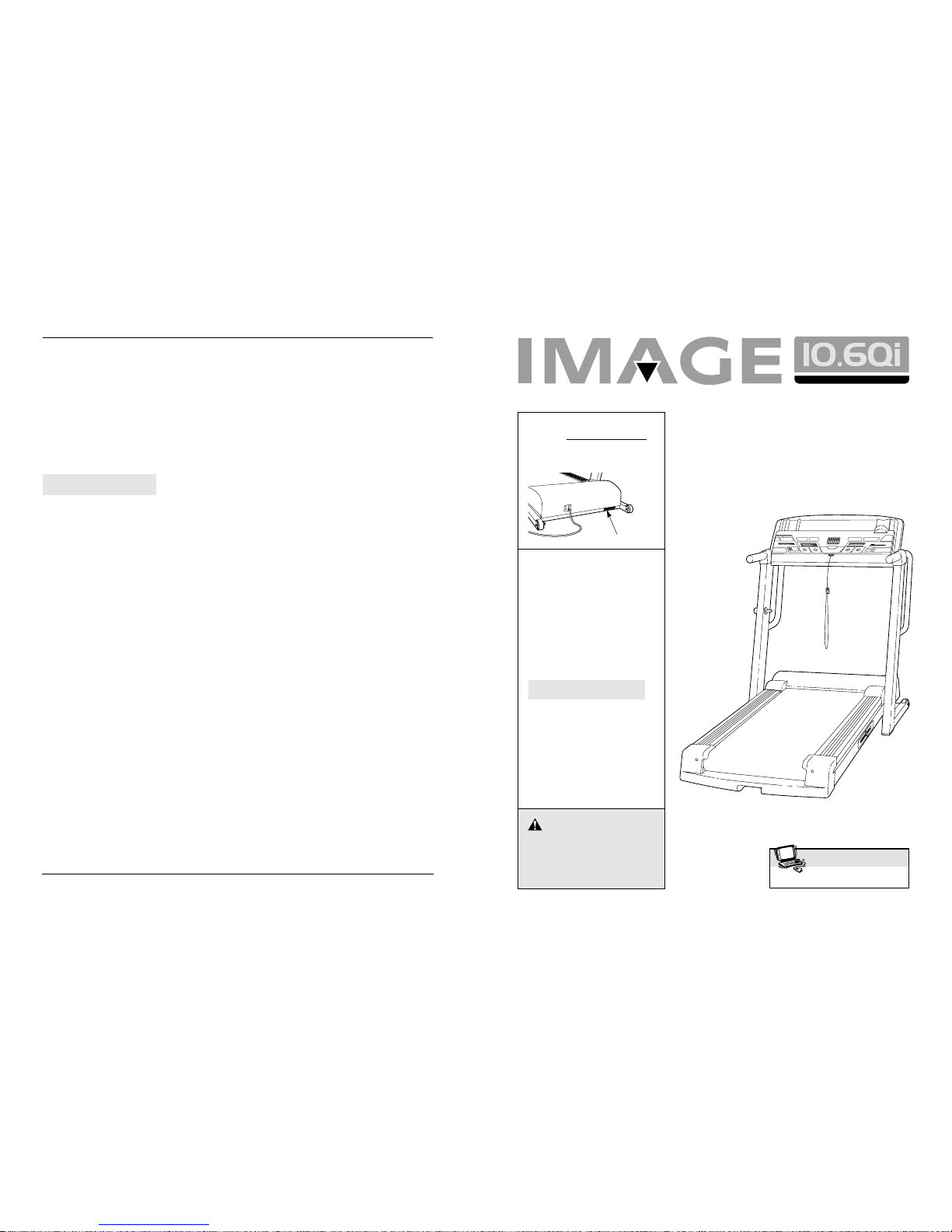
The decals shown at the right (1) and below (2) have beenplaced on the treadmill. If the decal is missing, or if it is not
legible, please call our Customer Service Department to order
a free replacement decal (see HOW TO ORDER REPLACEMENT PARTS on the back cover of this manual). Apply the
decal in the location shown.
SAVE THESE INSTRUCTIONS
4
29
Thank you for selecting the IMAGE®10.6Qi treadmill.
The IMAGE 10.6Qi treadmill combines advanced technology with innovative design to let you enjoy an effective form of cardiovascular exercise in the convenience
and privacy of your home. And when you’re not exercising, the unique IMAGE 10.6Qi can be folded up, requiring less than half the floor space of other treadmills.
For your benefit, read this manual carefully before
using the treadmill. If you have additional questions,
please call our Customer Service Department at
08457-089 009. To help us assist you, please note the
product model number and serial number before calling. The model number of the treadmill is IETL15910.
The serial number can be found on a decal attached to
the treadmill (see the front cover of this manual for the
location).
Before reading further, please familiarise yourself with
the parts that are labelled in the drawing below.
Handrail
Lock Knob
Key/Clip
Circuit
Breaker
Walking Belt
WARNING DECAL 1
Foot Rail
Rear Roller
Adjustment Bolts
Water Bottle
Holder (Bottle
not included)
Reading Rack
Accessory Tray
Console
Upright
On/Off
Switch
BEFORE YOU BEGIN
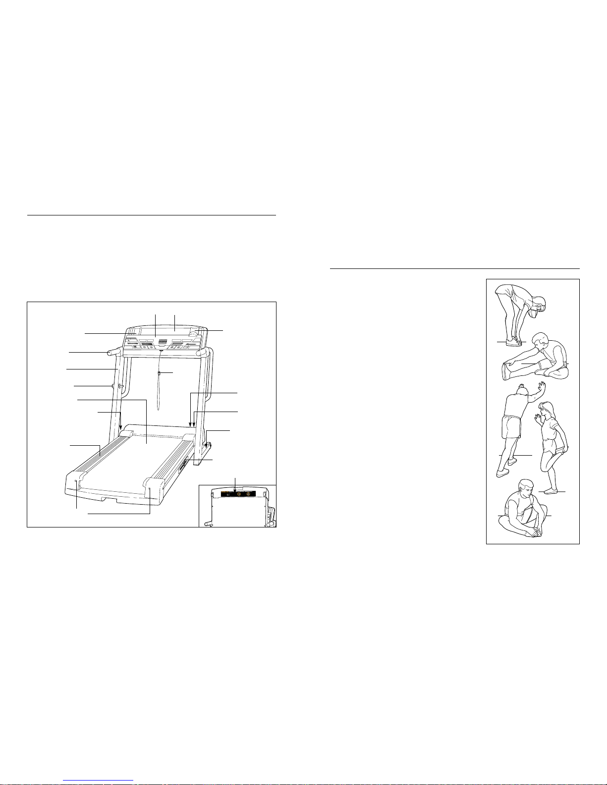
Cooling Down
Finish each workout with 5 to 10 minutes of stretching
to cool down. This will increase the flexibility of your
muscles and will help to prevent post-exercise problems.
EXERCISE FREQUENCY
To maintain or improve your condition, complete three
workouts each week, with at least one day of rest between workouts. After a few months, you may complete up to five workouts each week if desired. The key
to success is to make exercise a regular and enjoyable
part of your everyday life.
SUGGESTED STRETCHES
The correct form for several basic stretches is shown at the right.
Move slowly as you stretch—never bounce.
1. Toe Touch Stretch
Stand with your knees bent slightly and slowly bend forward from
your hips. Allow your back and shoulders to relax as you reach
down toward your toes as far as possible. Hold for 15 counts, then
relax. Repeat 3 times. Stretches: Hamstrings, back of knees and
back.
2. Hamstring Stretch
Sit with one leg extended. Bring the sole of the opposite foot toward you and rest it against the inner thigh of your extended leg.
Reach toward your toes as far as possible. Hold for 15 counts,
then relax. Repeat 3 times for each leg. Stretches: Hamstrings,
lower back and groin.
3. Calf/Achilles Stretch
With one leg in front of the other, reach forward and place your
hands against a wall. Keep your back leg straight and your back
foot flat on the floor. Bend your front leg, lean forward and move
your hips toward the wall. Hold for 15 counts, then relax. Repeat 3
times for each leg. To cause further stretching of the achilles tendons, bend your back leg as well. Stretches: Calves, achilles tendons and ankles.
4. Quadriceps Stretch
With one hand against a wall for balance, reach back and grasp
one foot with your other hand. Bring your heel as close to your
buttocks as possible. Hold for 15 counts, then relax. Repeat 3
times for each leg. Stretches: Quadriceps and hip muscles.
5. Inner Thigh Stretch
Sit with the soles of your feet together and your knees outward.
Pull your feet toward your groin area as far as possible. Hold for
15 counts, then relax. Repeat 3 times. Stretches: Quadriceps and
hip muscles.
1
2
3
4
5
Cushioning System
Adjustment Knob
WARNING DECAL 2
WARNING
DECAL 1
528
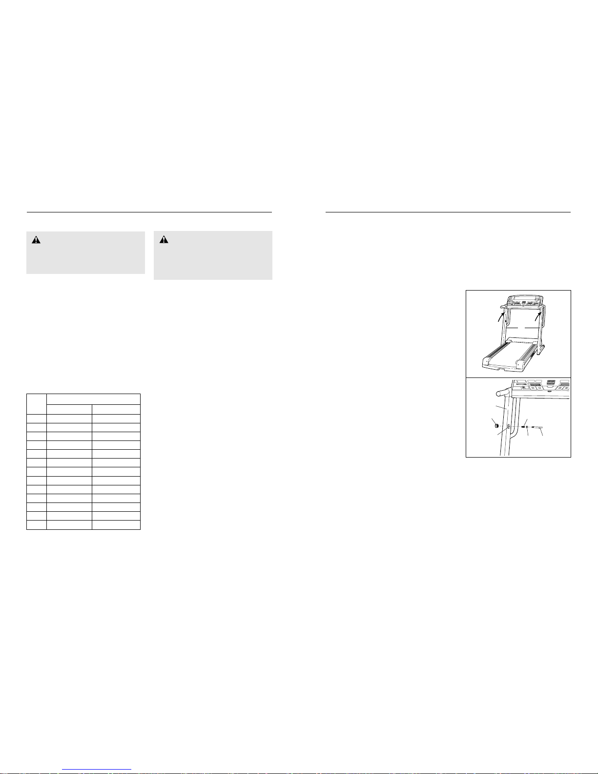
ASSEMBLY
Assembly requires two people. Set the treadmill in a cleared area and remove all packing materials. Do not
dispose of the packing materials until assembly is completed. No tools are required for assembly.
Note: The underside of the treadmill walking belt is coated with high-performance lubricant. During shipping, a
small amount of lubricant may be transferred to the top of the walking belt or the shipping carton. This is a normal
condition and does not affect treadmill performance. If there is lubricant on top of the walking belt, simply wipe off
the lubricant with a soft cloth and a mild, non-abrasive cleaner.
If further assistance is needed, please call our Customer Service Department at 08457-089 009.
1. With the help of a second person, carefully raise the
Uprights (65) until the treadmill is in the position shown.
2. Press the Lock Knob Sleeve (68) into the left Upright (65).
If necessary, use a rubber mallet to tap the Lock Knob
Sleeve into the Upright.
Remove the Lock Knob (67) from the Lock Pin (72).
Make sure that the Lock Pin Collar (70) and the Lock
Knob Spring (69) are on the Lock Pin as shown. (Note: If
there are two Lock Pin Collars, place one on each side of
the Spring.)Insert the Lock Pin into the Lock Knob Sleeve
(68) and the left Upright (65). Tighten the Lock Knob onto
the Lock Pin.
3. Make sure that all parts are tightened before you use the treadmill. Keep the included allen wrench in a
secure place. The allen wrench is used to adjust the walking belt (see pages 25 and 26). To protect the floor
or carpet from damage, place a mat under the treadmill.
65
1
72
70
69
67
68
65
2
CONDITIONING GUIDELINES
The following guidelines will help you to plan your exercise program. For more detailed information about
exercise, obtain a book or consult your physician.
EXERCISE INTENSITY
Whether your goal is to burn fat or strengthen your cardiovascular system, the key to achieving the desired
results is to exercise with the proper intensity. The
proper intensity level can be found by using your heart
rate as a guide. For effective exercise, your heart rate
should be maintained at a level between 65% and 85%
of your maximum heart rate as you exercise. This is
known as your training zone.
You can find your training zone in the table below.
Training zones are listed according to age and physical
condition.
Burning Fat
To burn fat, you must exercise at a low intensity level
for a sustained period of time. During the first few
minutes of exercise, your body uses easily accessible
carbohydrate calories for energy. Only after the first few
minutes of exercise does your body begin to use stored
fat calories for energy. If your goal is to burn fat, adjust
the intensity of your exercise until your heart rate is
near the low end of your training zone as you exercise.
Aerobic Exercise
If your goal is to strengthen your cardiovascular system, your exercise must be “aerobic.” Aerobic exercise
is activity that requires large amounts of oxygen for
prolonged periods of time. This increases the demand
on the heart to pump blood to the muscles, and on the
lungs to oxygenate the blood. For aerobic exercise,
adjust the intensity of your exercise until your heart
rate is near the middle of your training zone.
WORKOUT GUIDELINES
Each workout should include the following three important parts: (1) a warm-up, (2) training zone exercise,
and (3) a cool-down.
Warming Up
Warming up prepares the body for exercise by increasing circulation, delivering more oxygen to the muscles,
and raising the body temperature. Begin each workout
with 5 to 10 minutes of stretching and light exercise to
warm up (see SUGGESTED STRETCHES on page 29).
Training Zone Exercise
After warming up, increase the intensity of your exercise until your heart rate is in your training zone for 20
to 60 minutes. (During the first few weeks of your exercise program, do not keep your heart rate in your training zone for longer than 20 minutes.) Breathe regularly
and deeply as you exercise—never hold your breath.
WARNING:
Before beginning
this or any exercise program, consult your
physician. This is especially important for individuals over the age of 35 or individuals
with pre-existing health problems.
WARNING:The heart rate moni-
tor is not a medical device. Various factors, including your movement, may affect the accuracy of heart rate readings. The heart rate
monitor is intended only as an exercise aid in
determining heart rate trends in general.
20 138-167 133-162
25 136-166 132-160
30 135-164 130-158
35 134-162 129-156
40 132-161 127-155
45 131-159 125-153
50 129-156 124-150
55 127-155 122-149
60 126-153 121-147
65 125-151 119-145
70 123-150 118-144
75 122-147 117-142
80 120-146 115-140
Age
Unconditioned Conditioned
Training Zone (Beats/Min.)
6
27
HOW TO PUT ON THE HEART RATE MONITOR
The heart rate monitor consists of two components:
the chest strap and the sensor unit (see the drawing
below). Insert the tab on one end of the chest strap
through the hole in one end of the sensor unit. Press
the end of the sensor unit under the buckle on the chest
strap. The tab should be almost flush with the front of
the sensor unit.
Next, wrap the
heart rate monitor around your
chest and attach
the other end of
the chest strap to
the sensor unit.
Adjust the length
of the chest
strap, if necessary. The heart
rate monitor should be under your clothing, tight against
your skin, and as high under the pectoral muscles or
breasts as is comfortable. Make sure that the logo on
the sensor unit is facing forward and is right-side-up.
Pull the sensor unit away from your body a few inches
and locate the two electrode areas on the inner side.
The electrode areas are the areas covered by shallow
ridges. Using saline solution such as saliva or contact
lens solution, wet both electrode areas. Return the
sensor unit to a position against your chest.
HEART RATE MONITOR CARE AND MAINTENANCE
• Thoroughly dry the heart rate monitor after each
use. The heart rate monitor is activated when the
electrode areas are wetted and the heart rate monitor is put on; the heart rate monitor shuts off when it
is removed and the electrode areas are dried. If the
heart rate monitor is not dried after each use, it may
remain activated longer than necessary, draining the
battery prematurely.
• Store the heart rate monitor in a warm, dry place.
Do not store the heart rate monitor in a plastic bag
or other container that may trap moisture.
• Do not expose the heart rate monitor to direct
sunlight for extended periods of time; do not expose
it to temperatures above 122° Fahrenheit (50°
Celsius) or below 14° Fahrenheit (-10° Celsius).
• Do not excessively bend or stretch the sensor unit
when using or storing the heart rate monitor.
• Clean the sensor unit using a damp cloth—never
use alcohol, abrasives, or chemicals. The chest
strap may be hand washed and air dried.
HEART RATE MONITOR TROUBLE-SHOOTING
The instructions on the following pages explain
how the heart rate monitor is used with the console.
If the heart rate monitor does not function properly,
try the steps below.
• Make sure that the heart rate monitor is worn as described at the left. Note: If the heart rate monitor
does not function when positioned as described, try
moving it slightly lower or higher on your chest.
• Use saline solution such as saliva or contact lens
solution to wet the two electrode areas on the
sensor unit. If heart rate readings do not appear until
you begin perspiring, re-wet the electrode areas.
• As you walk or run on the treadmill, position yourself near the centre of the walking belt. For the
console to display heart rate readings, the user
must be within arm’s length of the console.
• The heart rate monitor is designed to work with
people who have normal heart rhythms. Heart rate
reading problems may be caused by medical
conditions such as premature ventricular contractions (pvcs), tachycardia bursts, and arrhythmia.
• The operation of the heart rate monitor can be
affected by magnetic interference caused by high
power lines or other sources. If it is suspected that
this is a problem, try relocating the treadmill.
• The CR2032 battery may need to be replaced (see
page 27).
HOW TO USE THE HEART RATE MONITOR
Chest Strap
Tabs
Sensor Unit
Tab
Buckle
PROBLEM: The heart rate monitor does not function properly
SOLUTION: a. If the heart rate monitor does not function properly, see HEART RATE MONITOR TROUBLE-
SHOOTING on page 6.
b. If the heart rate monitor still does not function properly, the battery
should be changed. To replace the battery, locate the battery cover
on the back of the sensor unit. Insert a coin into the slot in the cover
and turn the cover counterclockwise to the “open” position. Remove
the cover.
Remove the old battery from the sensor unit. Insert a new CR 2032
battery, making sure that the writing is on top. In addition, make sure
that the rubber gasket is in place in the sensor unit. Replace the battery cover and turn it to the closed position.
Battery
Rubber
Gasket
Battery Cover
Battery
Cover
b
 Loading...