

Page 1
®
IMAGE
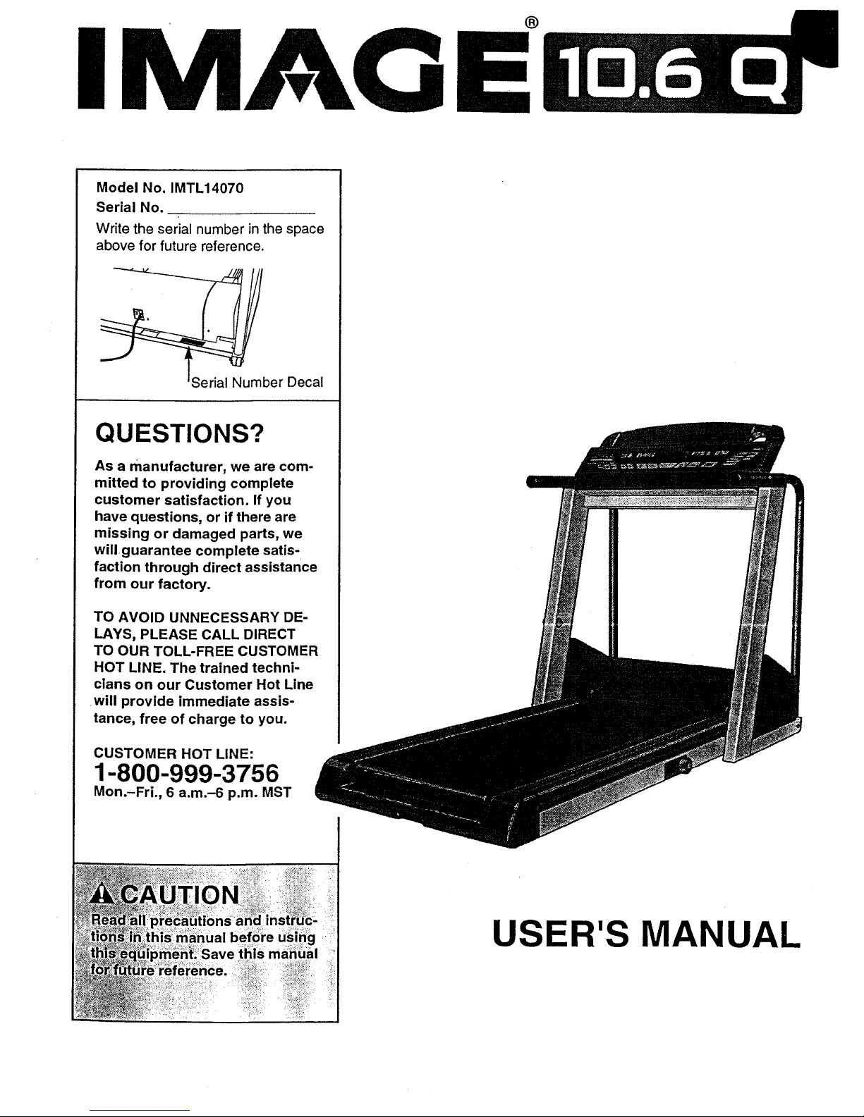
Model No. IMTL14070
Serial No.
Write the serial number in the space
above for future reference.
_ber Decal
QUESTIONS?
As a manufacturer, we are com-
mitted to providing complete
customer satisfaction. If you
have questions, or if there are
missing or damaged parts, we
will guarantee complete satis-
faction through direct assistance
from our factory.
TO AVOID UNNECESSARY DE-
LAYS, PLEASE CALL DIRECT
TO OUR TOLL-FREE CUSTOMER
HOT LINE. The trained techni-
cians on our Customer Hot Line
will provide immediate assis-
tance, free of charge to you.
CUSTOMER HOT LINE:
1-800-999-3756
Mon.-Fri., 6 a.m.-6 p.m. MST
USER'S MANUA
Page 2
TABLE OF CONTENTS
IMPORTANT PRECAUTIONS ................................................................. 2
BEFORE YOU BEGIN ....................................................................... 4
ASSEMBLY ............................................................................... 5
HOW TO USE THE HEART RATE MONITOR .................................................... 6
OPERATION AND ADJUSTMENT ............................................................. 7
HOW TO FOLD AND MOVE THE TREADMILL .................................................. 17
MAINTENANCE AND TROUBLE-SHOOTING ................................................... 18
CONDITIONING GUIDELINES ............................................................... 20
PART LIST ............................................................................... 22
ORDERING REPLACEMENT PARTS .......................................................... 23
LIMITED WARRANTY ............................................................... Back Cover
Note: An EXPLODED DRAWING is attached at the center of this manual. Save the EXPLODED DRAWING for
future reference.
IMPORTANT PRECAUTIONS
2
more than one person on the
at a time.
• _i_
lower
or if the
_n page 4 if the tread-
mill is:not w_rking pr'operiy.)
Page 3
THETREADMILLon
abletosafely
to ra
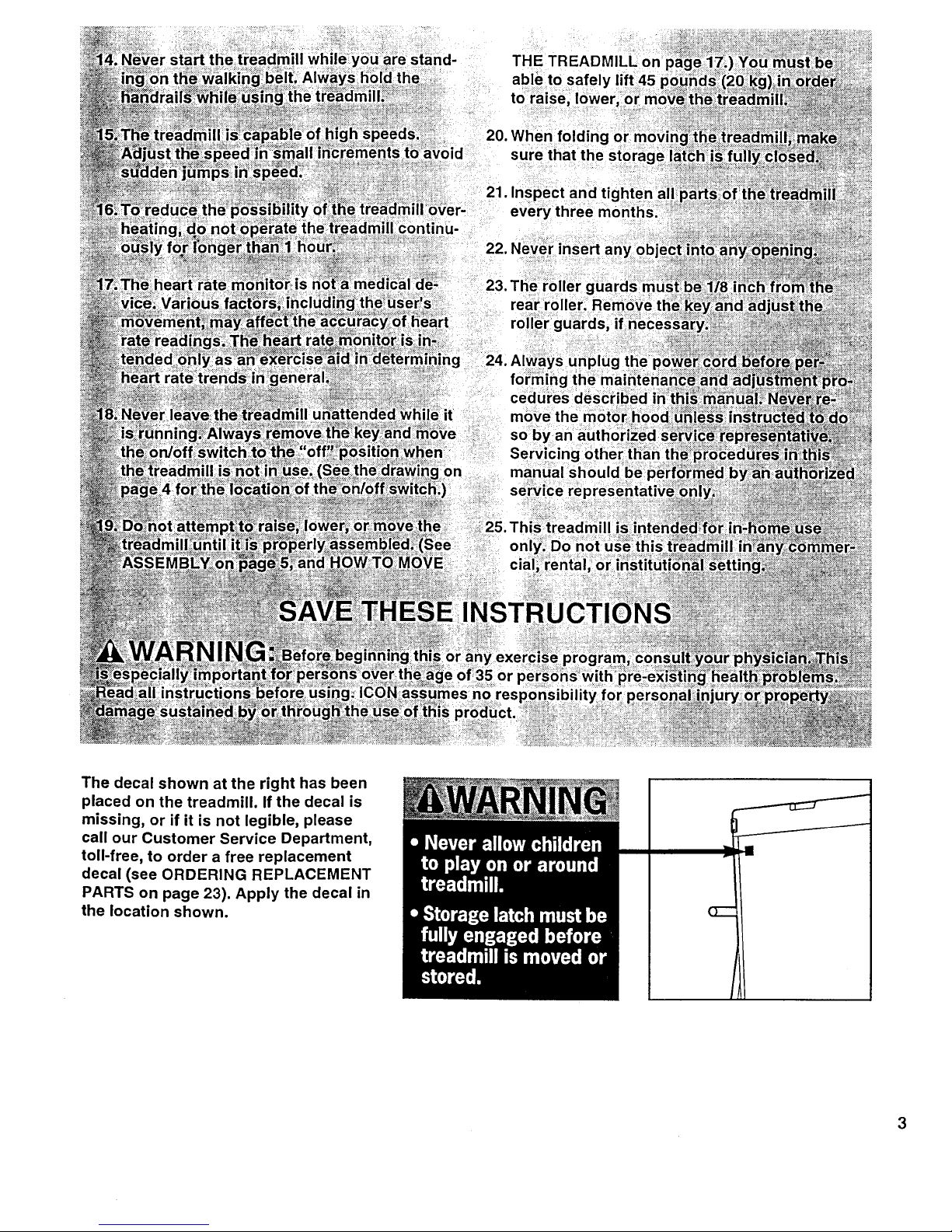
The decal shown at the right has been
placed on the treadmill. If the decal is
missing, or if it is not legible, please
call our Customer Service Department,
toll-free, to order a free replacement
decal (see ORDERING REPLACEMENT
PARTS on page 23). Apply the decal in
the location shown.
Page 4

BEFORE YOU BEGIN
Thank you for selecting the IMAGE ®10.6Q treadmill.
The IMAGE ®10.6Q treadmill combines advanced tech-
nology with innovative design to let you enjoy an effec-
tive form of cardiovascular exercise in the convenience
and privacy of your home. And when you're not exer-
cising, the unique IMAGE ®10.6Q can be folded up, re-
quiring less than half the floor space of other treadmills.
For your benefit, read this manual carefully before
using the treadmill. If you have additional questions,
please call our Customer Service Department toll-free
at 1-800-999-3756, Monday through Friday, 6 a.m.
until 6 p.m. Mountain Time (excluding holidays). To
help us assist you, please note the product model
number and serial number before calling. The model
number of the treadmill is IMTL14070. The serial num-
ber can be found on a decal attached to the treadmill
(see the front cover of this manual for the location).
Before reading further, please review the drawing
below and familiarize yourself with the parts that are
labeled.
Console Reading Rack
Accessory Tray
Handrail
Water Bottle
(Bottle
not included)
Foot
Upright
Lock Knob
Walking
On/Off
Switch
Circuit
_aker
Power Cord
RIGHT SIDE
_r Roller
Adjustment Bolt
BACK
Cushion Knob
Page 5
ASSEMBLY
Assembly requires two people. Set the treadmill in a cleared area and remove all packing materials. Do not
dispose of the packing materials untilassembly is completed. No tools are required for assembly.
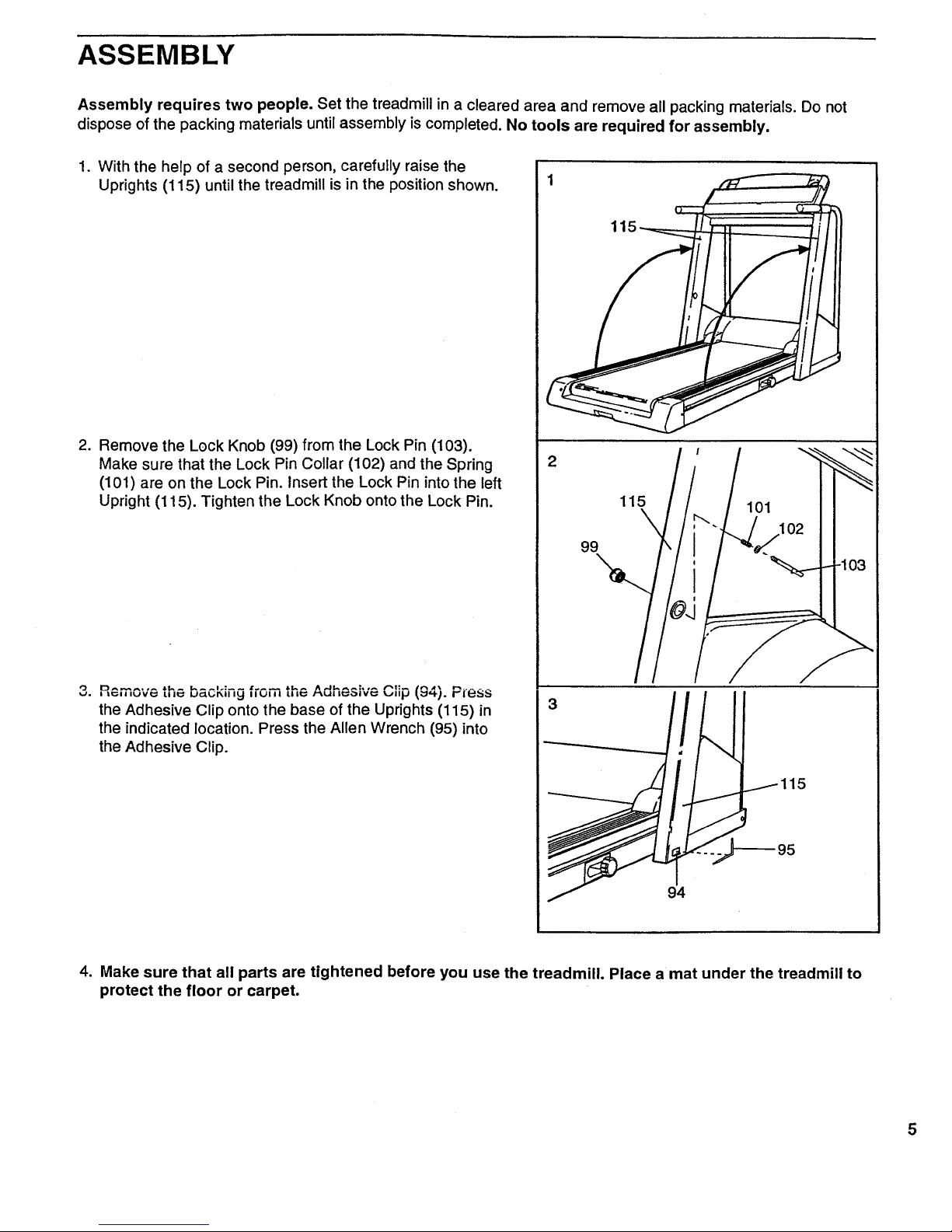
1. With the help of a second person, carefully raise the
Uprights (115) until the treadmill is in the position shown.
2. Remove the Lock Knob (99) from the Lock Pin (103).
Make sure that the Lock Pin Collar (102) and the Spring
(101) are on the Lock Pin. Insert the Lock Pin into the left
Upright (115). Tighten the Lock Knob onto the Lock Pin.
,,=,,,_v_ the baur..,y f,u,,a *"^ Adhesive ,.,,q_'"-(=,_j. Pless
the Adhesive Clip onto the base of the Uprights (115) in
the indicated location. Press the Allen Wrench (95) into
the Adhesive Clip.
115
2
115
\
99
101
115
4. Make sure that all parts are tightened before you use the treadmill. Place a mat under the treadmill to
protect the floor or carpet.
Page 6
HOW TO USE THE HEART RATE MONITOR
6
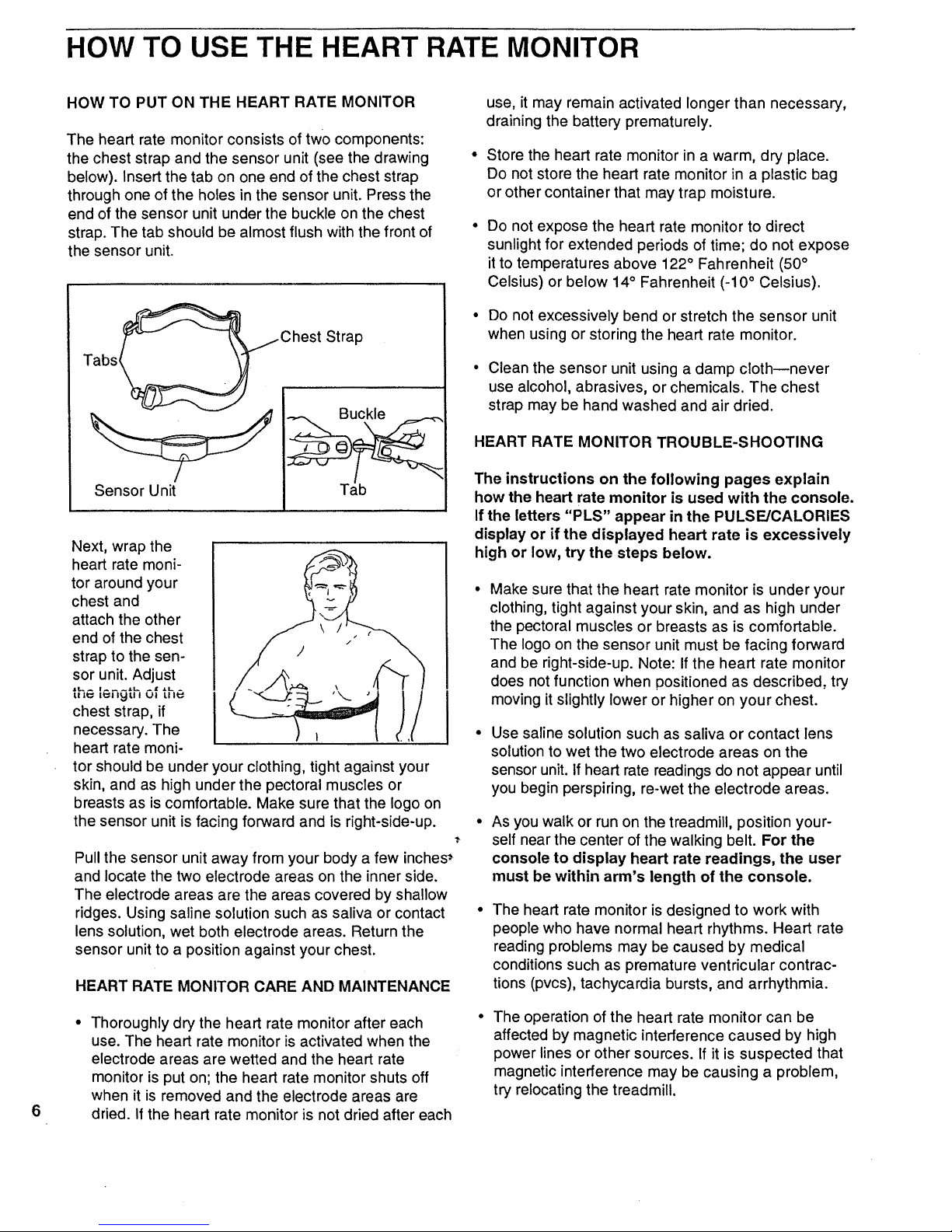
HOW TO PUT ON THE HEART RATE MONITOR
The heart rate monitor consists of two components:
the chest strap and the sensor unit (see the drawing °
below). Insert the tab on one end of the chest strap
through one of the holes in the sensor unit. Press the
end of the sensor unit under the buckle on the chest
strap. The tab should be almost flush with the front of °
the sensor unit.
_Chest Strap
Tabs__¢_
Next, wrap the
heart rate moni-
tor around your
chest and
attach the other
end of the chest
strap to the sen-
sor unit. Adjust
u,_ i_,_,l of the
chest strap, if
necessary. The
heart rate moni-
tor should be under your clothing, tight against your
skin, and as high under the pectoral muscles or
breasts as is comfortable. Make sure that the logo on
the sensor unit is facing forward and is right-side-up.
Pull the sensor unit away from your body a few inches_
and locate the two electrode areas on the inner side.
The electrode areas are the areas covered by shallow
ridges. Using saline solution such as saliva or contact
lens solution, wet both electrode areas. Return the
sensor unit to a position against your chest.
HEART RATE MONITOR CARE AND MAINTENANCE
Thoroughly dry the heart rate monitor after each
use. The heart rate monitor is activated when the
electrode areas are wetted and the heart rate
monitor is put on; the heart rate monitor shuts off
when it is removed and the electrode areas are
dried. If the heart rate monitor is not dried after each
use, it may remain activated longer than necessary,
draining the battery prematurely.
Store the heart rate monitor in a warm, dry place.
Do not store the heart rate monitor in a plastic bag
or other container that may trap moisture.
Do not expose the heart rate monitor to direct
sunlight for extended periods of time; do not expose
it to temperatures above 122 ° Fahrenheit (50°
Celsius) or below 14° Fahrenheit (-10 ° Celsius).
Do not excessively bend or stretch the sensor unit
when using or storing the heart rate monitor.
Clean the sensor unit using a damp cloth--never
use alcohol, abrasives, or chemicals. The chest
strap may be hand washed and air dried.
HEART RATE MONITOR TROUBLE-SHOOTING
The instructions on the following pages explain
how the heart rate monitor is used with the console.
If the letters "PLS" appear in the PULSE/CALORIES
display or if the displayed heart rate is excessively
high or low, try the steps below.
Make sure that the heart rate monitor is under your
clothing, tight against your skin, and as high under
the pectoral muscles or breasts as is comfortable.
The logo on the sensor unit must be facing forward
and be right-side-up. Note: If the heart rate monitor
does not function when positioned as described, try
moving it slightly lower or higher on your chest.
Use saline solution such as saliva or contact lens
solution to wet the two electrode areas on the
sensor unit. If heart rate readings do not appear until
you begin perspiring, re-wet the electrode areas.
As you walk or run on the treadmill, position your-
self near the center of the walking belt. For the
console to display heart rate readings, the user
must be within arm's length of the console.
The heart rate monitor is designed to work with
people who have normal heart rhythms. Heart rate
reading problems may be caused by medical
conditions such as premature ventricular contrac-
tions (pvcs), tachycardia bursts, and arrhythmia.
The operation of the heart rate monitor can be
affected by magnetic interference caused by high
power lines or other sources. If it is suspected that
magnetic interference may be causing a problem,
try relocating the treadmill.
Page 7
OPERATION AND ADJUSTMENT
THE PERFORMANT LUBETM WALKING BELT
Your treadmill features a walking belt coated with
PERFORMANT LUBE TM, a high-performance lubricant.
Important: Never apply silicone spray or other sub-
stances to the walking belt or the walking platform.
They will deteriorate the walking belt and cause ex-
cessive wear.
HOW TO PLUG IN THE POWER CORD
electric shock. This product is equipped with a cord
having an equipment-grounding conductor and a
grounding plug. Plug the power cord into a surge
protector, and plug the surge protector into an ap-
propriate outlet that is properly installed and
grounded in accordance with all local codes and
ordinances.
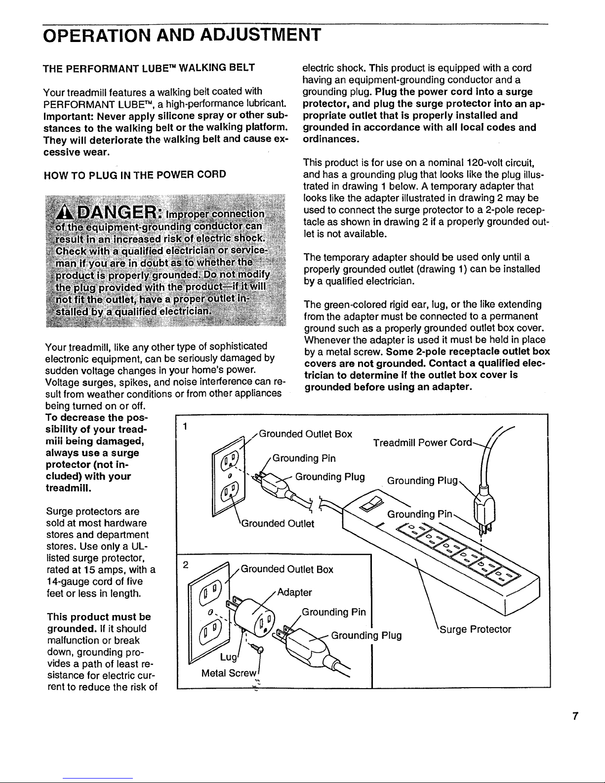
This product is for use on a nominal 120-volt circuit,
and has a grounding plug that looks like the plug illus-
trated in drawing 1 below. A temporary adapter that
looks like the adapter illustrated in drawing 2 may be
used to connect the surge protector to a 2-pole recep-
tacle as shown in drawing 2 if a properly grounded out-
let is not available.
The temporary adapter should be used only until a
properly grounded outlet (drawing 1) can be installed
by a qualified electrician.
Your treadmill, like any other type of sophisticated
electronic equipment, can be seriously damaged by
sudden voltage changes in your home's power.
Voltage surges, spikes, and noise interference can re-
sult from weather conditions or from other appliances
being turned on or off.
To decrease the pos-
sibility of your tread-
mill being damaged,
always use a surge
protector (not in-
cluded) with your
treadmill.
Surge protectors are
sold at most hardware
stores and department
stores. Use only a UL-
listed surge protector,
rated at 15 amps, with a
14-gauge cord of five
feet or less in length.
This product must be
grounded. If it should
malfunction or break
down, grounding pro-
vides a path of least re-
sistance for electric cur-
rent to reduce the risk of
1
The green-colored rigid ear, lug, or the like extending
from the adapter must be connected to a permanent
ground such as a properly grounded outlet box cover.
Whenever the adapter is used it must be held in place
by a metal screw. Some 2-pole receptacle outlet box
covers are not grounded. Contact a qualified elec-
trician to determine if the outlet box cover is
grounded before using an adapter.
/Grounded Outlet Box
Grounding Pin
'_unding Plug
3rounded Outlet
Treadmill Power Cord_.
Grounding
Plug
Surge Protector
7
Page 8
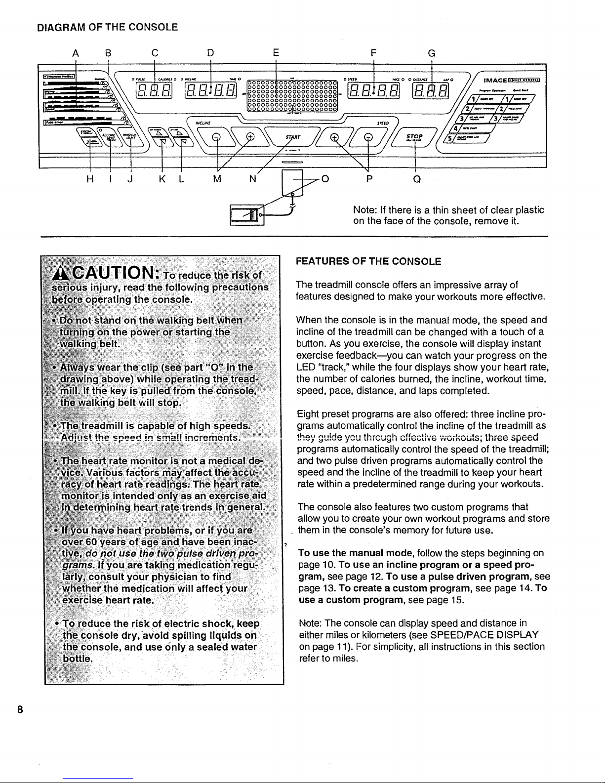
DIAGRAM OF THE CONSOLE
A B C D E F G
[
"_ ll-_tm I-I1 I1_-'1m_s="lm 1_8_°°o_%°°_o°°°8°°8°_ Ir'] L'3 o ol ILl _ El] // .....
° ............ , o - o_ .........
__ -- ,-r,-- -- -- ,I-- -- 00000 000000000000 -- -- ----
!3000000000000000000C " -- // ,,,/_ i_/_/
_8o°°°%%°_°°8%°°°8_ ///W_--i,'I---/
,,=- " ,_<, ......c ......, .... % .... 9 ,,,,;) "/iv _- I;l==J
/ i,i :::=: "\ .....
H I J K L M N P Q
Note: If there is a thin sheet of clear plastic
on the face of the console, remove it.
risk of electric shock, keep
dry, avoid spilling liquids on
and use only a sealed water
FEATURES OF THE CONSOLE
The treadmill console offers an impressive array of
features designed to make your workouts more effective.
When the console is in the manual mode, the speed and
incline of the treadmill can be changed with a touch of a
button. As you exercise, the console will display instant
exercise feedback--you can watch your progress on the
LED "track," while the four displays show your heart rate,
the number of calories burned, the incline, workout time,
speed, pace, distance, and laps completed.
Eight preset programs are also offered: three incline pro-
grams automatically control the incline of the treadmill as
programs automaticallycontrolthespeed ofthetreadmill;
and two pulsedrivenprograms automaticallycontrolthe
speed and the inclineofthetreadmilltokeep your heart
ratewithina predeterminedrangeduringyourworkouts.
The console also features two custom programs that
allow you to create your own workout programs and store
. them in the console's memory for future use.
To use the manual mode, follow the steps beginning on
page 10. To use an incline program or a speed pro-
gram, see page 12. To use a pulse driven program, see
page 13. To create a custom program, see page 14. To
use a custom program, see page 15.
Note: The console can display speed and distance in
either miles or kilometers (see SPEED/PACE DISPLAY
on page 11). For simplicity, all instructions in this section
refer to miles.
Page 9

DIAGRAM OF THE CONSOLE
Refer to the drawing on the opposite page.
A.
Workout profiles--These profiles show how the
incline of the treadmill will change during incline pro-
grams, how the speed will change during speed pro-
grams, and how your heart rate will change
during pulse driven programs.
B. Mode indicatorsmThese indicators show whether
the manual (node is selected or whether one of the
eight preset programs is selected.
C.
PULSE/CALORIES display--This display shows both
your heart rate (if the heart rate monitor is worn) and
the approximate number of calories you have
burned. The display will alternate between one num-
ber and the other every seven seconds. This display
is also used to enter your weight into the console.
O.
INCLINE/TIME display--This display shows both the
incline of the treadmill and the elapsed time. (If a
preset program or a custom program is selected, the
display will show the time remaining in the program.)
The display will alternate between one number and
the other every seven seconds. This display is also
used to enter your age into the console.
K. SET WEIGHT buttons--These buttons are used to
enter your weight into the console.
L. SET AGE buttons--These buttons are used to enter
your age into the console.
M.
INCLINE buttons--These buttons are used to
change the incline of the treadmill. The incline range
is 0% to 14%. Note: The incline can be adjusted
only while the walking belt is moving.
N. START button--This button is used to start the
walking belt when the manual mode, a preset
program, or a custom program is selected.
O. Key with clip_The key turns the console on and off.
The clip is worn on the waistband of your clothes.
P.
SPEED buttons--These buttons control the speed
of the walking belt. The speed range is 0.5 mph to
12 mph. Note: When the START button is pressed,
the walking belt will begin to move at 1.0 mph.
Q. STOP buttonmThis button is used to pause or stop
the walking belt when the manual mode, a preset
program, or a custom program is selected.
HOW TO TURN ON THE POWER
E.
F.
G.
H.
J.
LED matrix--When the manual mode is selected, this
matrix shows your progress on an LED track. When a
preset program or a custom program is selected, the
matrix shows the program's workout profile.
SPEED/PACE display_This display shows both the
speed ot the walking belt and your current pace
(minutes per mile). The display will altemate between
one number and the other every seven seconds.
DISTANCE/LAP display--This display shows both
the distance you have walked and the number of
laps you have completed (one lap equals 1/4 mile).
The display will alternate between one number and
the other every seven seconds.
CUSTOM PROGRAM buttons--These buttons are
used to select custom programs 1 and 2.
RECORD button_This button is used to create
custom programs.
PROGRAM SELECT button_This button is used to
select the manual mode and the eight preset pro-
grams. Note: If the walking belt is moving when the
SELECT PROGRAM button is pressed, the walking
belt will slow to a stop and the displays will _e reset.
In addition, the treadmill may automatically _djust to
the lowest incline level.
n
B
lZl
Plug in the power Cord (see page 7). All displays
and indicators on the console will flash once and
then darken. Note: If the key is in the console when
the power cord is plugged in, the letters "PO" will
flash in the SPEED/PACE display. If this occurs,
remove the key.
Make sure that the
on/off switch
located on the
front of the tread-
mill is in the "on"
position.
Stand on the foot
rails of the tread-
mill and insert the
key into the con-
sole. After a mo-
ment, the MAN-
UAL indicator will
light, the letters
,m,
"LbS" will appear in the PULSE/CALORIES dis-
play, the letters "AGE" will appear in the INCLINE/
TIME display, and the LED track in the center of
the console will light. Every few seconds,the words
"PRESS START" will scroll across the I-Eb matrix.
9
Page 10

L1
10
Insert the key into the console.
See HOW TO TURN ON THE POWER on page 9.
Note: When you are familiar with the operation of
the console, you may go directly to step 5 if desired.
The first time you use the console, please read and
follow all steps.
Select the MANUAL mode.
When the key
is inserted, the
manual mode
will automati-
cally be se-
lected and the
MANUAL indi-
cator will light.
If a program
!! o,,.,. I
ff m r_
__
"t---;%2-4
L
has been selected, press the PROGRAM SELECT
button repeatedly to select the manual mode again.
Enter your weight and age if desired.
Although it is not necessary to enter your weight and
age to use the manual mode, the CALORIES display
will be more accurate if these numbers are entered.
To enter your weight,
press either of the SET
WEIGHT buttons. The
current weight setting
PULSE/CALORIES
display. Press the SET
WEIGHT buttons again to enter your weight. Each
time one of the buttons is pressed, the weight set-
ting will change by 1 pound. If one of the buttons is
held down, the weight setting will change in incre-
ments of 5 pounds.
17,-'
Toenteryouragef,
press either of the SET o o_ ..... o
AGE buttons. The
current age setting will I
appear in the INCLINE/
TIME display. To enter c
your age, press the
SET AGE buttons again. Each time one of the but-
tons is pressed, the age setting will change by 1
year. If one of the buttons is held down, the age set-
ting will change in increments of 5 years. Note:
Once you have entered your weight and age, the
numbers will be saved in the console's memory,
even if the power cord is unplugged.
B
O
Put on the heart rate monitor if desired.
For the PULSE/CALORIES display to show your
heart rate, the heart rate monitor must be worn. To
put on the heart rate monitor, see HOW TO USE
THE HEART RATE MONITOR on page 6.
Press the START button.
Press the START button to start the walking belt.
The LED track in the center of the console will
disappear in a counterclockwise direction. One
flashing indicator will then re-appear and the
walking belt wilt begin to move at 1.0 mph. Hold the
handrails and step onto the walking belt.
The LED track
represents 1/4
of a mile. As
you exercise,
the indicators
will light one
at a time until
the entire
track is lit.
_000000000_0000®0000_
_000000000000000000_
_00@000000000000@00_,
_000000000000000®00_"
_000000000000000@00_
_ooooooooo_oooooooo_
_oooooooo_.ooo oooo_
.----.--_ r . . _ ,,.--.----
The track will then disappear in a counterclockwise
direction and a new lap will begin.
To stop the walking belt momentarily, press the
STOP button once. All displays will pause and the
INCLINE/TIME display will begin to flash. To restart
the walking belt, press the START button as de-
scribed above. To stop the walking belt and reset all
displays, hold down the STOP button for two sec-
onds. The console will then be in the same state as
if the key had just been in._.rt_.d
Adjust the incline and speed of the treadmill.
While the walking belt is moving, the incline of the
treadmill can be adjusted with the INCLINE
buttons. Each time one of the buttons is pressed,
the incline will change by 0.5%. The buttons can
be held down to change the incline quickly. The
incline range is 0% to 14%. Note: After the buttons
are pressed, it may take a moment for the treadmill to
reach the selected incline setting.
To adjust the speed of the walking belt, press the
SPEED buttons. Each time one of the buttons is
pressed, the speed will change by 0.1 mph. The but-
tons can be held down to change the speed in incre-
ments of 0.5 mph. The speed range of the walking
belt is 0.5 mph to 12.0 mph.
Page 11

B Follow your progress
with the four displays.
PULSE/CALORIES dis-
play--This display opULSE c,,O,l_S= 0
I '-')
shows both your heart I-_1
rate (if the heart rate I_-i _-i
monitor is worn) and the
approximate number of
calories you have
burned. The display will alternate between one num-
ber and the other every seven seconds.
Note: The heart rate monitor will sample your heart
rate every few seconds; it may take up to ten sec-
onds before an accurate heart rate is shown. If your
heart rate is not shown, see HEART RATE
MONITOR TROUBLE-SHOOTING on page 6.
INCLINE/TIME
display--This display
shows both the incline of
the treadmill and the
elapsed time. (If a preset
program or a custom
program is selected, the
I
0 iNCLINE TIME 0 |
(i,=,.,-,,_11
I
I-_i'1_1
display will show the time remaining in the program.)
The display will alternate between one number and
the other every seven seconds.
DISTANCE/LAP dis-
play--This display
shows both the dis-
tance you have walked
and the number of laps
you have completed
(one lap equals 1/4
mile). The display will alternate between one number
and the other every seven seconds.
I
• DISTANCE LAP 0 |
Note: If the speed is displayed in miles per hour, the
distance will be displayed in miles; if the speed is
displayed in kilometers per hour, the distance will be
displayed in kilometers.
When you are finished exercising, stop the
walking belt and remove the key.
Step onto the foot rails, press the STOP button, and
remove the key from the console. Store the key in a
secure place. In addition, press the on/off switch to
the "off" position. (See the drawing near the bottom
of page 9.)
Note: Each time the INCLINE buttons are pressed,
the display will show the incline setting.
SPEED/PACE
display--This display
shows both the speed of
the walking belt and
your current pace
(minutes per mile). The
display will alternate be-
• SPEED
I
t
I..! --!]
i. _1] I
tween one number and the other every seven
seconds.
Note: Each time the SPEED buttons are pressed,
the display will show the speed setting.
Note: The speed can be
displayed in either miles
per hour (mph) or kilo-
meters per hour (kph).
To check the unit of
measurement, first hold
down the STOP button
while inserting the key
0 SPEED PACE 0
..1;- )
0 SPEED PACE 0
.IF,'7 ]
into the console. The SPEED/PACE display will
show an "E" for "English" (miles) or an "M" for
"Metric" (kilometers). Press the SPEED "+" .b.uttonto
change the unit of measurement. Remove"ahd then
reinsert the key.
11
Page 12

n
B
Insert the key into the console.
See HOW TO TURN ON THE POWER on page 9.
Select one of the incline or speed programs.
When the key
is inserted, the
manual mode
will automati-
cally be se-
lected and the
MANUAL indi-
cator will light.
To select one
,-:-_____
-- _ . --
tI,.=-------
.'_' '_"", _, -- r_\ \ I
of the incline or speed programs, press the PRO-
GRAM SELECT button repeatedly until the desired
INCLINE or SPEED indicator lights. Note: The first
incline program and the first speed program are
twenty-minute programs. All other preset programs
are thirty-minute programs.
When an in-
cline or speed
program is se-
lected, the
LED matrix will
show all of the
incline or
speed settings
of the program.
z_
_000000000'000000'000_
_O00000000000eO0000_
_000000000000000000_.
_000000000000000000_"
_000000000000000000_
_000000000_000000000_
_oeeeoooe_lo?eooeeo®_
..... J
......... J
_,=,.,i. _u.,,_piugm_1, has lweJli.yincline settings,
and each speed program has twenty speed set-
tings. One setting is shown in each vertical column
of the LED matrix. The first column will be flashing.
Note: Every few seconds, the words "PRESS
START" will scroll across the LED matrix.
B
Enter your weight and age if desired.
Although it is not necessary to enter your weight
and age to use an incline program or a speed pro-
gram, the CALORIES display will be more accurate
if these numbers are entered.
To enter you weight and age, refer to step 3 on
page 10. If you have already entered your weight
and age, or if you do not want to enter this informa-
tion, go to step 4.
B
B
Put on the heart rate monitor if desired.
For the PULSE/CALORIES display to show your
heart rate, the heart rate monitor must be worn. To
put on the heart rate monitor, see HOW TO USE
THE HEART RATE MONITOR on page 6.
Press the START button.
Press the START button to start the program. After
a moment, the walking belt will begin to move. Hold
the handrails and begin walking.
If an incline program is selected: When the
START button is pressed, the walking belt will begin
to move at 1.0 mph and the incline will adjust to the
incline setting shown in the first column of the LED
matrix. After one minute (or 90 seconds if a thirty-
minute program is selected), the second column of
the LED matrix will begin to flash and the incline will
adjust to the incline setting shown in the second col-
umn. After another minute (or 90 seconds), the third
column will begin to flash and the incline will adjust
to the setting shown in the third column. The pro-
gram will continue in this way until the twentieth col-
umn is flashing and no time remains in the TIME dis-
play. The walking belt will then slow to a stop.
The speed of the walking belt can be adjusted during
the incline program with the SPEED buttons. To stop
the program momentarily, press the STOP button
once. All displays will pause and the INCLINE/TIME
display will begin to flash. To restart the program,
press the START button. To end the program be-
fore it is completed, hold down the STOP button for
state as if the key had just been inserted.
While the incline program is in progress, the diffi-
culty level of the program can be adjusted, if de-
sired, with the INCLINE buttons. Press the INCLINE
"+" button once. The letters "MAX" will appear in the
LED matrix, and the INCLINE/TIME display will
show the maximum incline that the treadmill will
reach during the program. This information will be
displayed for three seconds. Press the INCLINE "+"
button again. Each time the button is pressed, the
maximum incline setting and all other settings of the
program will increase slightly. The INCLINE "-" but-
ton can be used in the same way to decrease the
difficulty level of the program. Note: The profile
shown in the LED matrix will not change; the profile
shows relative incline settings.
12
Page 13

B
If a speed program is selected: When the START
button is pressed, the walking belt will begin to move
at 1.0 mph, the speed setting shown in the first col-
umn of the LED matrix. After one minute (or 90 sec-
onds if a thirty-minute program is selected), the sec-
ond column of the LED matrix will begin to flash and
the speed will adjust to the speed setting shown in
the second column. After another minute (or 90 sec-
onds), the third column will begin to flash and the
speed will adjust to the setting shown in the third col-
umn. The program will continue in this way until the
twentieth column is flashing and no time remains in
the TIME display. The walking belt will then slow to a
stop.
The incline of the treadmill can be adjusted during
the speed program with the INCLINE buttons. To
stop the program momentarily, press the STOP but-
ton once. All displays will pause and the INCLINE/
TIME display will begin to flash. To restart the pro-
gram, press the START button. To end the program
before it is completed, hold down the STOP button
for two seconds. The console will then be in the
same state as if the key had just been inserted.
While the speed program is in progress, the difficulty
level of the program can be adjusted, if desired, with
the SPEED buttons. Press the SPEED %" button
once. The letters "MAX" will appear in the LED ma-
trix, and the SPEED/PACE display will show the
maximum speed that the treadmill will reach during
the program. This information will be displayed for
three seconds. Press the SPEED "+" button again.
Each time the button is pressed, the maximum
speed setting and all other settings of the program
•..:t!
w,l inci_ease ................ SPEED" " '-.........
s,u_luy. _al_ - UULLU'_U_, ue
used in the same way to decrease the difficulty level
of the program. Note: The profile shown in the LED
matrix will not change; the profile shows relative
speed settings.
Follow your progress with the LED displays,
Refer to step 7 on page 11.
Remove the key from the console.
When the program has ended, remove the key from
the console. All displays and indicators on the con-
sole will darken.
[!
lg
Insert the key into the console.
See HOW TO TURN ON THE POWER on page 9.
Select one of the pulse driven programs.
When the key
is inserted, the
manual mode
will automati-
cally be se-
lected and the
MANUAL indi-
cator will light.
To select one
_
---. \
of the pulse driven
programs, press the PROGRAM SELECT button re-
peatedly until the desired PULSE DRIVEN indicator
lights. Note: Both pulse driven programs are thirty-
minute programs.
The pulse
driven
programs
automatically
control the
speed and
incline of the
treadmill to
keep your
Jn
_OOOOOOOOO_OOOOOOeee_
@ooooooooooeeeeeeee_
_@oooooooooooooooooo_
_oooooeeeeeeooeooeo_ _
_oooooooooooooooooo_
_®oooooooo_ooooooooo_
_oeoooooooj?eoeeeoeo_
\ /
_ ......... _(.-._--
heart rate near predetermined settings during your
..... '.... • '^'"^- ^"_" .... i_^ "" .... programs isVVVI_t_/UL. V¥1I_II one UI LIIU }JUl_:_ UllVt_ll
selected, the LED matrix will show all of the heart
rate settings of the program. Each program has
twenty heart rate settings. One setting is shown in
each vertical column of the LED matrix. The first
column will be flashing. Note: Every few seconds,
the words "ENTER AGE" will scroll across the LED
matrix.
Enter your weight and age.
Although it is not necessary to enter your weight to
use a pulse driven program, you must enter your
age before one of these programs can be
started.
To enter you weight and age, refer to step 3 on page
10. If you have already entered your weight and
age, press either of the SET AGE buttons to ver-
ify the age setting. The words "PRESS START" will
then scroll across the LED matrix every few sec0nds.
13
Page 14

B
g
Put on the heart rate monitor.
The heart rate monitor must be worn when a pulse
driven program is used. See HOW TO USE THE
HEART RATE MONITOR on page 6. Note: A pulse
driven program can be started without a heart rate
reading; however, the speed and/or incline of the
treadmill will automatically decrease if your heart rate
is not detected during the program.
Press the START button.
Press the START button to start the program. After a
moment, the walking belt will begin to move. Hold
the handrails and begin walking.
While the first column of the LED matrix is flashing,
the walking belt will move at 1.5 mph. After 90 sec-
onds, the second column of the LED matrix will
begin to flash. As the program progresses, the
speed and/or incline of the treadmill will change at
any time to keep your heart rate near the heart rate
setting shown in the flashing column. When the
twentieth column begins to flash, the walking belt will
move at 1.5 mph until no time remains in the TIME
display. The walking belt wilt then slow to a stop and
the program will be completed.
if your heart rate is not detected during the program,
the letters "PLS" will flash in the PULSE/CALORIES
display and the speed and/or incline of the treadmill
will automatically decrease. See HEART RATE
MONITOR TROUBLE-SHOOTING on page 6.
While the program is in progress, minor adjustments
,.,_,,_,_ ,,,a_,_ ,,_,,,_ op_u or III_111I_:;_of LIItc_LII_ClLAJIIIIII
with the SPEED or INCLINE buttons. However, if
you increase the speed, the incline will automatically
decrease; if you decrease the speed, the incline will
increase. If you increase the incline, the speed will
decrease; if you decrease the incline, the speed will
increase. The console will always attempt to keep
your heart rate near the heart rate setting shown in
the flashing column. Note: When the incline reaches:
the lowest setting, the speed cannot be increased
any further. When the incline reaches the highest
setting, the speed cannot be decreased any further.
H ollow your progress with the LED displays.
Refer to step 7 on page 11.
B Remove the key from the console.
When the program has ended, remove the key from
the console. All displays and indicators on the con-
sole will darken.
O Insert the key into the console.
See HOW TO TURN ON THE POWER on page 9.
B
Select one of the custom programs.
To select one of the
custom programs,
O SPEED
press the CUSTOM
PROGRAM 1 or [1- I--1
CUSTOM PROGRAM • L
2 button. The letters
"CP 1" or "CP 2" will
appear in the SPEED/
PACE display to show which program you have
selected.
Custom programs are workout programs that you
create. The programs are stored in the console's
memory, and can be changed as many times as
desired. Custom programs control both the speed
and the incline of the treadmill. When one of the
custom programs is selected, the LED matrix will
show the speed settings of the program (until you
have created a program, all speed settings will be
the same). The first column will be flashing. Note:
Every few seconds, the words "PRESS START" will
scroll across the LED matrix.
k3
Enter your weight and age if desired.
It is not necessary to enter your weight and age to
create a custom program; however, the CALORIES
display will be more accurate if these numbers are
entered.
To enter you weight and age, refer to step 3 on
page 10. If you have already entered your weight
and age, or if you do not want to enter this informa-
tion, go to step 4.
E!
Press the START button.
Press the START button to start the program. After a
moment, the walking belt will begin to move. Hold
the handrails and begin walking.
14
Page 15

_ ress the RECORD button and program the de-
sired speed and incline settings.
When the RECORD button is pressed, the indicator
on the button will light. Speed and incline settings
can be programmed only when the indicator on
the button is lit.
Refer to the
LED matrix.
Each custom
program is "
divided into
one-minute
segments. One
speed setting
and one incline
fooo0oooooc_ooooooooooi
iooooooooooooooooooooi
..|OOOOO OOOOOOOOOOOOOOOj
rooooooooooooooooooool-
lOeOOOOOOOOOOOOOOOOOOl
ioooeooeooehooooeoooool
LeeoQe eoooeleoeo o eeeoeJ
\ /
setting can be programmed for each one-minute
segment. The speed setting of the first segment is
shown in the flashing column of the LED matrix.
(The incline settings are not shown in the LED ma-
trix.) To program the desired speed and incline set-
tings for the first segment, simply adjust the speed
and incline of the treadmill to the desired levels with
the SPEED and INCLINE buttons. Every few times
the SPEED "+" or "-" button is pressed, an additional
LED will light or darken in the flashing column.
When the first one-minute segment of the program
iscompleted, the current speed setting and the cur-
rent incline setting will be stored in memory. All
columns in the LED matrix will then move one posi-
tion to the left, and the speed setting of the second
segment will be shown in the flashing column.
Program speed and incline settings for the second
S_'_'_'_'__S ,4,_r,.,;k,_,__k_,_
_ Insert the key into the console.
See HOW TO TURN ON THE POWER on page 9.
B
8
Select one of the custom programs.
To select one of the
custom programs,
press the CUSTOM
PROGRAM 1 or
CUSTOM PROGRAM
2 button. The letters
"CP 1" or "CP 2" will
appear in the SPEED/
PACE display to show which program is selected.
0 SPEED PACE 0
I/:/-' 11
When a custom program is selected, the LED matrix
will show the speed settings of the program. If the
program is more than twenty minutes long, only the
first nineteen settings will be shown. The first column
will be flashing. Note: Every few seconds, the words
"PRESS START" will scroll across the LED matrix.
Enter your weight and age if desired.
It is not necessary to enter your weight and age to use
a custom program; however, the CALORIES display
will be more accurate if these numbers are entered.
To enter you weight and age, refer to step 3 on
page 10. If you have already entered your weight
and age, or if you do not want to enter this informa-
tion, go to step 4.
r4
Repeat this procedure until you have programmed
speed and incline settings for as many segments as
desired. Custom programs can have from one to
forty segments. When you are finished, hold down
the STOP button for two seconds. The speed and in-
cline settings you programmed and the number of
segments will then be stored in memory. To use the
program again, see HOW TO USE A CUSTOM PRO-
GRAM at the right.
Note: To pause the program temporarily while you
are programming speed and incline settings, press
the STOP button once. All displays will pause and the
TIME display will begin to flash. To restart the pro-
gram, press the START button.
Remove the key from the console.
When the program has ended, remove the key from
the console. All displays and indicators on,t_h_econ-
sole will darken.
Press the START button.
Press the START button to start the program. After a
moment, the walking belt will begin to move. Hold
the handrails and begin walking.
Refer to the
LED matrix.
Each custom
program is di-
vided into one-
minute seg-
ments. One
speed setting
and one in-
_00000000(_00000000_
_O0000@O00000eO0000_
_O000OOOOOO00OO0000_.
=_oooooeoeeooooeoooo_'
_oooooooeeeeeeeeeoo_
_oeoe®oooe_eoeeeeeo_
_eoooeeeoe_=eooooooe__,.
cline setting are programmed for each segment. The
speed setting of the first segment is shown in the
flashing column of the LED matrix. The speed set-
tings of the next six segments are shown in.the six
columns to the right. (The incline settings-a?e not
shown in the program display.)
15
Page 16

When the first one-minute segment of the program
is completed, all columns of the LED matrix will
move one position to the left, the speed setting of
the second segment will be shown in the flashing
column, and the speed of the treadmill will change
accordingly. The incline will also change according
to the settings that you programmed previously.
The program will continue in this way until the speed
setting of the last segment is shown in the flashing
column and no time remains in the TIME display.
The walking belt will then slow to a stop.
Note: If the program is too easy or too difficult, the
speed or incline setting of the current segment can be
adjusted with the SPEED or INCLINE buttons.
Adjustments will not be stored in memory. To repro-
gram the speed or incline setting of the current seg-
ment, press the RECORD button. The indicator on the
button willlight. Speed and incline settings can be
programmed only when the indicator on the button
is lit. Adjust the speed or inclinesettingof the current
segment with the SPEED or INCLINE buttons. After
the segment is completed, press the RECORD button
again. The new setting willthen be stored in memory.
To stop the program momentarily, press the STOP
button once. All displays will pause and the INCLINE/
TIME display will begin to flash. To restart the pro-
gram, press the START button. To end the program
before it is completed, hold down the STOP button
for two seconds. The console will then be in the
same state as if the key had just been inserted.
B ollow your progress with the LED displays.
Refer to step 7 on page 11.
Remove the key from the console.
When the program has ended, remove the key from
the console. All displays and indicators on the con-
sole will darken.
HOW TO SELECT THE INFORMATION MODE
The console features an information mode that keeps
track of the total time and distance accumulated on the
treadmill.
To access the information mode, hold down the STOP
button while inserting the key into the console. The
INCLINE/TIME display will show the total number of
hours accumulated on the treadmill. The DISTANCE/
LAP display will show the number of miles accumulated
(if the total number of miles exceeds 999, the thousands
and ten thousands digits will be shown in the right half
of the SPEED/PACE display). The left half of the
SPEED/PACE display will show which unit of measure-
ment is currently selected: an "E" for "English" (miles) or
an "M" for "Metric" (kilometers). To change the unit of
measurement, press the SPEED "+" button.
To exit the information mode, remove the key from the
console.
HOW TO ADJUST THE CUSHION LEVEL OF THE
TREADMILL
The treadmill is specially designed to cushion the
impact as you walk or run. The cushion level is con-
trolled with the knob on the right side of the treadmill.
For a softer cushion level, turn the knob counterclock-
wise. For a firmer cushion level, turn the knob clock-
wise. Note: The faster you run on the treadmill, the
firmer the cushion level should be. If the cushion level is
too soft, the treadmill may bounce
excessively.
'' i .... i "/_,_ ....
_'_/_/ "Cushion
Knob
16
Page 17

HOW TO FOLD AND MOVE THE TREADMILL
HOW TO FOLD THE TREADMILL FOR STORAGE
Before folding the treadmill, unplug the power cord. Caution:
You must be able to safely lift 45 pounds (20 kg) in order
to raise, lower, or move the treadmill.
.
Hold the treadmill with your hands in the locations shown
at the right. To decrease the possibility of injury, bend
your legs and keep your back straight. As you raise
the treadmill, make sure to lift with your legs rather
than your back. Raise the treadmill about halfway to the
vertical position.
.
Move your right hand to the position shown and hold the
treadmill firmly. Hold the lock knob with your left hand
and pull it to the side. Raise the treadmill until the lock
knob is aligned with the catch. Slowly release the knob.
Make sure that the pin on the lock knob is inside of
the catch.
To protect the floor or carpet from damage, place a
mat under the treadmill. Keep the treadmill out of
direct sunlight. Do not leave the treadmill in the stor-
age position in temperatures above 85° Fahrenheit.
1
2
HOW TO MOVE THE TREADMILL
Before moving the treadmill, convert the treadmill to the stor-
age position as described above, rvlake sure [hat the pin
on the lock knob is inside of the catch.
1. Hold the handrails and place one foot on the base as
shown.
2. Tilt the treadmill back until it rolls freely on the front
wheels. Carefully move the treadmill to the desired loca-
tion. Never move the treadmill without tipping it back.
To reduce the risk of injury, use extreme caution
while moving the treadmill. Do not move the treadmill
over an uneven surface.
3. Place one foot on the base and carefully lower the tread-
mill until it is resting on the base.
Front Wheels
HOW TO LOWER THE TREADMILL FOR USE
1. Refer to drawing 2 above. Hold the upper end of the treadmill with your right hand as shown. Hold the lock
knob with your left hand and pull it to the side. Pivot the treadmill down a few inches.
2. Refer to drawing 1 above. Hold the treadmill firmly with both hands, and lower the treadmill to the flo_)_.To
decrease the possibility of injury, bend your legs and keep your back straight.
17
Page 18

MAINTENANCE AND TROUBLE-SHOOTING
Most treadmill problems can be solved by following the steps below. Find the symptom that applies, and
follow the steps listed. If further assistance is needed, please call our Customer Service Department toll-
free at 1-800-999-3756, Monday through Friday, 6 a.m. until 6 p.m. Mountain Time (excluding holidays).
1. SYMPTOM: THE POWER DOES NOT TURN ON
a. Make sure that the power cord is plugged into a surge protector, and that the surge protector is plugged into
a properly grounded outlet. (See HOW TO PLUG IN THE POWER CORD on page 7.) Use only a UL-listed
surge protector, rated at 15 amps, with a 14-gauge cord of five feet or less in length.
b. After the power cord has been plugged in, make sure that the key is fully inserted into the console. (See
step 3 on page 9.)
C.
Check the circuit breaker located on the treadmill near the
power cord. If the switch protrudes as shown, the circuit
breaker has tripped. To reset the circuit breaker, wait for five
minutes and then press the switch back in.
d. Check the on/off switch located at the front of the treadmill
near the power cord. The switch must be in the "on" position.
2; SYMPTOM: THE POWER TURNS OFF DURING USE
c
Tripped
Reset
a. Check the circuit breaker located on the treadmill frame near the power cord (see 1. c. above). If the circuit
breaker has tripped, wait for five minutes and then press the switch back in.
b. Make sure that the power cord is plugged in.
c. Remove the key from the console. Reinsert the key fully into the console. (See step 3 on page 9.)
d. Make sure that the on/off switch is in the "on" position. (See 1. d. above.)
e. If the treadmill still will not run, please call our Customer Service Department, toll-free.
3. SYMPTOM: THE WALKING BELT SLOWS WHEN WALKED ON
a. Use only a UL-listed surge protector, rated at 15 amps, with a 14-gauge cord of five feet or less in length.
b. If the walking belt still slows when walked on, please call our Customer Service Department, toll-free.
4. SYMPTOM: THE WALKING BELT IS OFF-CENTER WHEN WALKED ON
a. If the walking belt has shifted to the left, first remove the key and
UNPLUG THE POWER CORD. Using the allen wrench, turn the
left adjustment bolt clockwise 1/4 of a turn. Plug in the power
cord, insert the key and run the treadmill for a few minutes.
Repeat until the walking belt is centered.
18
Page 19

b.Ifthewalkingbelthasshiftedtotheright,firstremovethekey
andUNPLUGTHEPOWERCORD.Usingtheallenwrench,turn
theleftadjustmentboltcounterclockwise1/4ofaturn.Plugin
thepowercord,insertthekeyandrunthetreadmillforafew
minutes.Repeatuntilthewalkingbeltiscentered.
5. SYMPTOM: THE HEART RATE MONITOR DOES NOT FUNCTION PROPERLY
a. If the heajtmte monitor does not function properly, refer to HEART RATE MONITOR TROUBLE-
SHOOTING on page 6.
b. If the heart rate monitor still does not function properly, the battery should be
changed. To replace the battery, locate the battery cover on the back of the sen-
sor unit. Insert a coin into the slot in the cover and turn the cover counterclock-
wise to the "open" position. Remove the cover.
Remove the old battery from the sensor unit. Insert a new battery, making sure
that the writing is on top. In addition, make sure that the rubber gasket is in place
in the sensor unit. Replace the battery cover and turn it to the closed position.
Q
I
6. SYMPTOM: AN ERROR CODE (El, E20, E21, E22, E23, OR E24) APPEARS ON THE CONSOLE
a. If an error code appears, remove the key from the console, wait for a moment, and then reinsert it. If the
error code appears again, call our Customer Service Department. Do not use the treadmill until the problem
is corrected.
19
Page 20

CONDITIONING GUIDELINES
The following guidelines will help you to plan your ex-
ercise program. Remember--these are general guide-
lines. For more detailed information about exercise,
obtain a book or consult your physician.
EXERCISE INTENSITY
Whether your goal is to burn fat or strengthen your car-
diovascular system, the key to achieving the desired
results is to exercise with the proper intensity. The
proper intensity level can be found by using your heart
rate as a guide. For effective exercise, your heart rate
should be maintained at a level between 70% and 85%
of your maximum heart rate as you exercise. This is
known as your training zone.
You can find your training zone in the table below.
Training zones are listed according to age and physical
condition.
Age
20
25
30
35
40
45
50
55
60
65
70
75
8O
85
Training Zone (Beats/Min.)
Unconditioned
138-167
136-166
135-164
134-162
132-161
131-159
129-156
127-155
126-153
125-151
123-150
122-147
120-146
118-144
Conditioned
133-162
132-160
130-158
129-156
127-155
125-153
124-150
122-149
121-147
119-145
118-144
117-142
115-140
114-139
Burning Fat
To burn fat, you must exercise at a low intensity level
for a sustained period of time. During the first few
minutes of exercise, your body uses easily accessible
carbohydrate calories for energy. Only after the first few
minutes of exercise does your body begin to use stored
fat calories for energy. If your goal is to burn fat, adjust
the intensity of your exercise until your heart rate is
near the low end of your training zone as you exercise.
Aerobic Exercise
If your goal is to strengthen your cardiovascular sys-
tem, your exercise must be "aerobic." Aerobic exercise
is activity that requires large amounts of oxygen for
prolonged periods of time. This increases the demand
on the heart to pump blood to the muscles, and on the
lungs to oxygenate the blood. For aerobic exercise,
adjust the intensity of your exercise until your heart
rate is near the middle of your training zone.
tAIPIDVtSI I1" P'I IIf'_l'?_l ii, iPr_
Ilva ii\vv l _1V IIJl_" LIl_lr" ,0
Each workout should include the following three impor-
tant parts: (1) a warm-up, (2) training zone exercise,
and (3) a cool-down.
Warm-up
Warming up prepares the body for exercise by increas-
ing circulation, delivering more oxygen to the muscles,
and raising the body temperature. Begin each workout
with 5 to 10 minutes of stretching and light exercise to
warm up (see SUGGESTED STRETCHES on page 21).
Training Zone Exercise
After warming up, increase the intensity of your exer-
cise until your heart rate is in your training zone for 20
to 60 minutes. (During the first few weeks of your exer-
cise program, do not keep your heart rate in your train-
ing zone for longer than 20 minutes.) Breathe regularly
and deeply as you exercise--never hold your breath.
2O
Page 21

Cool-down
Finish each workout with 5 to 10 minutes of stretching
to cool down. This will increase the flexibility of your
muscles and will help to prevent post-exercise problems.
Exercise Frequency
To maintain or improve your condition, complete three
workouts each week, with at least one day of rest be-
tween workouts. After a few months, you may com-
plete up to five workouts each week if desired.
The key to success is to make exercise a regular and
enjoyable part of your everyday life.
SUGGESTED STRETCHES
The correct form for several basic stretches is shown at the
right. Move slowly as you stretch--never bounce.
1. Toe Touch Stretch
Stand with your knees bent slightly and slowly bend forward
from your hips. Allow your back and shoulders to relax as you
reach down toward your toes as far as possible. Hold for 15
counts, then relax. Repeat 3 times. Stretches: Hamstrings,
back of knees and back.
2. Hamstring Stretch
Sit with one leg extended. Bring the sole of the opposite foot
toward you and rest it against the inner thigh of your extended
leg. Reach toward your toes as far as possible. Hold for 15
counts, then relax. Repeat 3 times for each leg. Stretches:
Hamstrings, lower back and groin.
3. Calf/Achilles Stretch
With one leg in front of the other, reach forward and place your
hands against a wall. Keep your back leg straight and your
back foot flat on the floor. Bend your front leg, lean forward and
move your hips toward the wall. Hold for 15 counts, then relax.
Repeat 3 times for each leg. To cause further stretching of the
achilles tendons, bend your back leg as well. Stretches:
Calves, achilles tendons and ankles.
4. Quadriceps Stretch
With one hand against a wall for balance, reach back and
grasp one foot with your other hand. Bring your heel as close
to your buttocks as possible. Hold for 15 counts, then relax.
Repeat 3 times for each leg. Stretches: Quadriceps and hip
muscles.
5. Inner Thigh Stretch
Sit with the soles of your feet together and your knees outward.
Pull your feet toward your groin area as far as possible. Hold
for 15 counts, then relax. Repeat 3 times. Str_:hes:
Quadriceps and hip muscles.
2
3
4
21
Page 22

22
PART LISTmModel No. IMTL14070 R0897A
Note: To identify the parts listed below, refer to the EXPLODED DRAWING attached at the center of this manual.
Key No. Qty. Description Key No. Qty. Description
1 1 Frame 54 2 Shock
2 38 Screw 55 1 Walking Belt
3 4 Spring Nut 56 8 Belly Pan Spacer
4 4 Spring Bolt 57 1 Motor Pivot Nut
5 2 Cushion Spring 58 1 Cushion Shaft
6 4 Isolator 59 1 Belly Pan
7 2 Cushion Adj. Rack 60 1 Right Foot Rail
8 8 Rack Screw 61 5 8" Cable Tie
9 2 Cushion Adj. Gear 62 1 Motor Bracket
10" 1 Motor/Pulley/Flywheel/Fan 63 1 Tie Holder
11 1 Latch Housing 64 1 Releasable tie
12 1 Left Foot Rail 65 1 Short Rear Roller Adj. Bolt
13 2 Rear Platform Screw 66 1 Rear Roller Endcap
14 2 Roller Guard 66 1 Rear Roller Endcap
15 1 Walking Platform 67 2 Endcap Pad
16 1 Rear Roller 68 1 Pulse Monitor
17 2 Incline Pivot Bolt 69 1 Monitor Strap
18 1 Front Roller/Pulley 70 1 Console
19 4 Motor Bolt 71 4 Upright Cap Screw
20 1 Console Base 72 1 Motor
21 4 Bracket Screw 73 4 Upright Cap
22 2 Hood Anchor 74 8 Console Screw
23 2 Hood Anchor Bracket 75 1 Console Plate
24 2 Motor Bracket Nut 76 6 Console Plate Screw
25 2 Motor Bracket Washer 77 1 Hood
26 3 Long Hood Bracket 78 5 Hood Screw
27 2 Belt Guide 79 1 Cushion Knob
28 1 Motor Tension Bolt 80 1 Power Board
29 1 Outlet Bracket 81 4 Plastic Stand-Off
30 1 Circuit Breaker 82 6 Electronics Screw
31 1 Power Cord 83 1 Controller
32 1 Power Cord Grommet 84 1 Upright Wire Harness
33 1 On/Off Switch 85 2 Isolator Bolt
34 1 Incline Leg 86 1 Electronics Plate
35 1 Front Roller Adj. Bolt 87 1 Upright Cover (right inside)
36 3 Roller Adj. Washer 88 2 Upright Cover
37 2 Incline Leg Spacer 89 2 Platform Screw (front)
38 2 Incline Leg Pivot Nut _ 90 2 Wheel Bolt
39 4 Motor Nut _ 91 4 Front Wheel
40 1 Motor Pivot Bolt 92 2 Incline Spacer
41 1 Motor Pivot Bolt Washer 93 2 Wheel Nut
42 1 Key!Clip 94 1 Adhesive Clip
43 2 Flange Nut 95 1 Allen Wrench
44 1 Motor Tension Nut 96 2 Upright Cap
45 2 Small Nut 97 2 Handrail Foam
46 1 Speed Bracket Screw 98 2 Handrail Endcap
47 2 Small Bolt 99 1 Lock Knob
48 2 Sensor 100 1 Lock Knob Sleeve
49 1 Speed Sensor Bracket 101 1 Lock Knob Spring
50 1 Speed Disk 102 1 Lock Pin Collar
51 2 Hood Anchor Screw 103 1 Lock Pin
52 1 Long Rear Roller Adj. Bolt 104 1 Pin Clip
53 2 Sensor Wire 105 2 Platform Washer
Page 23

Key No. Qty. Description Key No. Qty. Description
106 1 Stop Bracket 124 1
107 2 Incline Motor Bolt 125 2
108 2 Small Star Washer 126 1
109 1 Incline Disk 127 1
110 2 Incline Nut 128 1
111 1 Incline Motor 129 2
112 1 I-Bolt 130 2
113 1 Roller Tension Spring # 1
114 1 Belly Pan Hinge # 1
115 1 Upright/Base # 1
116 1 Upright Cover (left outside) # 1
117 2 Roller Tension Washer # 1
118 1 Battery Cover # 1
119 1 Warning Decal # 1
120 1 Receiver # 1
121 1 Console Wire Harness
122 1 8" Ground Wire
123 1 Set Screw
Pulley/Flywheel/Fan
Foam Pad
Motor Belt
4" Wire Tie
Roll Pin
Isolator Nut
Motor Tension Washer
14"White Wire, 2 Female
14"White Wire, Male/Female
14" Blue Wire, Male/Female
8" Blue Wire, 2 Female
4" Black Wire, 2 Female
9" Black Wire, Male/Female
8" Red Wire, Male/Female
User's Manual
* Includes all parts shown in the box
# These parts are not illustrated
ORDERING REPLACEMENT PARTS
To order replacement parts, call our Customer Service Department toll-free at 1-800-999-3756, Monday through
Friday, 6 a.m. until 6 p.m. Mountain Time (excluding holidays). When ordering parts, please be prepared to give
the following information:
• The MODEL NUMBER of the product (IMTL14070).
• The NAME of the product (IMAGE ®10.6Q treadmill).
• The SERIAL NUMBER of the product (refer to the front cover of this manual).
° The KEY NUMBER of the part(s) (see the PART LIST at the left and the EXPLODED DRAWING attached at
the center of this manual).
• The DESCRIPTION of the part(s) (see the PART LIST at the left and the EXPLODED DRAWING
attached at the center of this manual).
If possible, place the treadmill near your telephone for easy reference when calling.
23
Page 24

7O
42
69
2O
118
97
125
120
121
75
116
99
115
74
., I06
97
98
47
77
78
82
91
8O
81
21 86
o-
71
9O
94
87
78
78
88
78
°_---
Page 25

EXPLODED DRAWING--Model No. IMTL14070
12
2
I
3
I 113
13
14
66
65
67
2
52
59
RO897A
4
124
19
30 31
o.-" 21
28 26
54
Note: To identifythe parts shown on this explo_ded
drawing, refer to the PART LIST on page 22 of the
USER'S MANUAL.
Page 26

I LIMITED WARRANTY ]
WHAT IS COVERED--The entire IMAGE 10.6Q ("Product") is warranted to be free of all defects in material and workman-
ship.
WHO IS COVERED--The original purchaser or any person receiving the Product as a gift from the original purchaser.
HOW LONG IS IT COVERED--ICON Health & Fitness, Inc. ("ICON"), warrants the hood, covers, belly pan, and decals for
six months after the date of purchase. The belt and deck are covered for one year after the date of purchase. All mechani-
cal components are covered for one year after the date of purchase. All electrical components are covered for one year
after the date of purchase. Labor is covered for one year within the contiguous United States.
WHO PAYS TRANSPORTATION AND INSURANCE FOR SERViCE--If the Product or any covered part must be returned
to a service facility for repairs, we will pay all transportation and insurance charges for the first year for electrical and me-
chanical components.
WHAT WE DO TO CORRECT COVERED DEFECTS--We will ship to you, without charge, any replacement part or com-
ponent, providing the repairs are authorized by ICON first and are performed by an ICON trained and authorized service
provider, or, at our option, we will replace the Product.
WHAT IS NOT COVERED--Any failures or damage caused by unauthorized service, misuse, accident, negligence, im-
proper assembly or installation, alterations, modifications without our written authorization or by failure on your part to use,
operate, and maintain as set out in your User's Manual ("Manual").
WHAT YOU MUST DO--Retain proof of purchase (our receipt of the attached registration card assures registration of pur-
chase information but is not required); store, operate, and maintain the Product as specified in the Manual; notify our
Customer Service Department of any defect within 10 days after discovery ofthe defect; as instructed, return any defected
part for replacement or, if necessary, the entire product,for repair.
USER'S MANUAL--It is VERY IMPORTANT THAT YOU READ THE MANUAL before operating the Product. Remember
to do the periodic maintenance requirements specified in the Manual to assure proper operation and your continued satis-
faction.
WARRANTY REGISTRATIONwAttached is a registration card. COMPLETE AND MAIL THE CARD IMMEDIATELY. Our
receipt assures that your name, address, and date of purchase are on file as a registered owner of the Product. Failure to
return the card will not affect your rights under this warranty. Being a registered owner assures coverage in the event you
lose your proof of purchase. In any event, always retain proof of purchase, such as your bill of sale.
HOW TO GET PARTS AND SERVICE--Simply call our Customer Service Department at 1-800-999-3756 and tell them
your name and address and the serial number of your Product. They will tell you how to get a part replaced, or if neces-
sary, arrange for service where your Product is located or advise you how to ship the Product for service. Before shipping,
always obtain a Return Authorization Number (RA No.) from our Customer Service Department; securely pack your
Product (save the original shipping carton if possible); put the RA No. on the outside of the carton and insure the product.
Include a letter explaining the product or problem and a copy of your proof of purchase if you believe the service is covered
by warranty.
ICON is not responsible or liable for indirect, special or consequential damages arising out of or in connection with the use
or performance of the product or damages with respect to any economic loss, loss of property, loss of revenues or profits,
loss of enjoyment or use, costs of removal, installation or ot*herconsequential damages of whatsoever nature. Some states
do not allow the exclusion or limitation of incidental or co_hsequentialdamages. Accordingly, the above limitation may not
apply to you.
The warranty extended hereunder is in lieu of any and all other warranties and any implied warranties of merchantability or
fitness for a particular purpose is limited in its scope and duration to the terms set forth herein. Some states do not allow
limitations on how long an implied warranty lasts. Accordingly, the above limitation may not apply to you.
No one is authorized to change, modify or extend the terms of this limited warranty.
This warranty gives you specific legal rights and you may have other rights which vary from state to state.
ICON HEALTH & FITNESS, INC., 1500 S. 1000 W., LOGAN, UT 84321-9813
Part No. 137083 G02932-C R0897A Printed in USA © 1997 ICON Health & Fitness, Inc.
 Loading...