

Imac RM600, RM1000, RM3000, RM5000, RM2000 Installation Instructions Manual
...
Installation Instructions for Line Mounted Romet Meters
Caution:
•Rough handling of the meter must be avoided to prevent
damage. A Romet rotary meter is a precise gas volume
measuring instrument manufactured to very tight tolerances.
•Always transports the meter capped at both ends and without
oil in order to prevent damage, dirt or oil contamination of the
meter.
•Always add oil after the meter has been correctly installed.
Installation Considerations:
•The piping and flange position of the meter set should be
such that there is adequate area spacing between the meter
and any pipe, wall or other obstruction. This spacing will
allow for the addition or removal of devices, such as, a meter
module, batteries or any other auxiliary instrument (eg.
ROMET AdEC™)
•Furthermore all full faced pipe flanges installed (raised
flanges are not recommended) must be level and spaced so
that the meter together with the top and bottom gaskets can be
positioned between the flanges easily with the least amount of
air gap (maximum 1/16” per linear foot of flange) before
tightening. If the meter is not level, it is possible to
improperly fill the oil reserves or over-stress the meter after
tightening the flange bolts. This condition may cause the
meter to read incorrectly or result in complete meter failure.
•Care must also be taken to ensure that the piping and flanges
are aligned correctly in relation to the meter (maximum 1/16”
in all directions). DO NOT use the meter to correct
misaligned piping or flanges. Excessive misalignment or
distance between piping or flanges may overstress the meter
body when the flange bolts are tightened. Severe over-stress
may cause the meter to read incorrectly or result in complete
meter failure. The use of a spool piece to help level and align
the pipe flanges with the meter can be helpful.
•A meter bypass is recommended to facilitate any future
maintenance or calibration considerations.
•To protect the meter (and any other critical component) from
internal damage, the meter set must be free of foreign
materials (weld beads, rust scale, grease, etc) The use of a
filter upstream of the meter is strongly recommended.
Typical filters include the IMAC Gasket Strainer or flanged
and threaded ‘T’ Strainers.
Installation Instructions:
•A quick check of the rotary meter should be performed
before installation. First remove the capping from each end of
the meter openings. Blow air lightly into the meter inlet
(making sure the meter outlet is not obstructed) The meter
impellers should rotate freely and eventually come to a
gradual stop. Should the impellers stop suddenly or not rotate
at all, it will be necessary to carefully remove any obstruction
before installation. If this is not possible the meter should be
returned to the service shop for further examination.
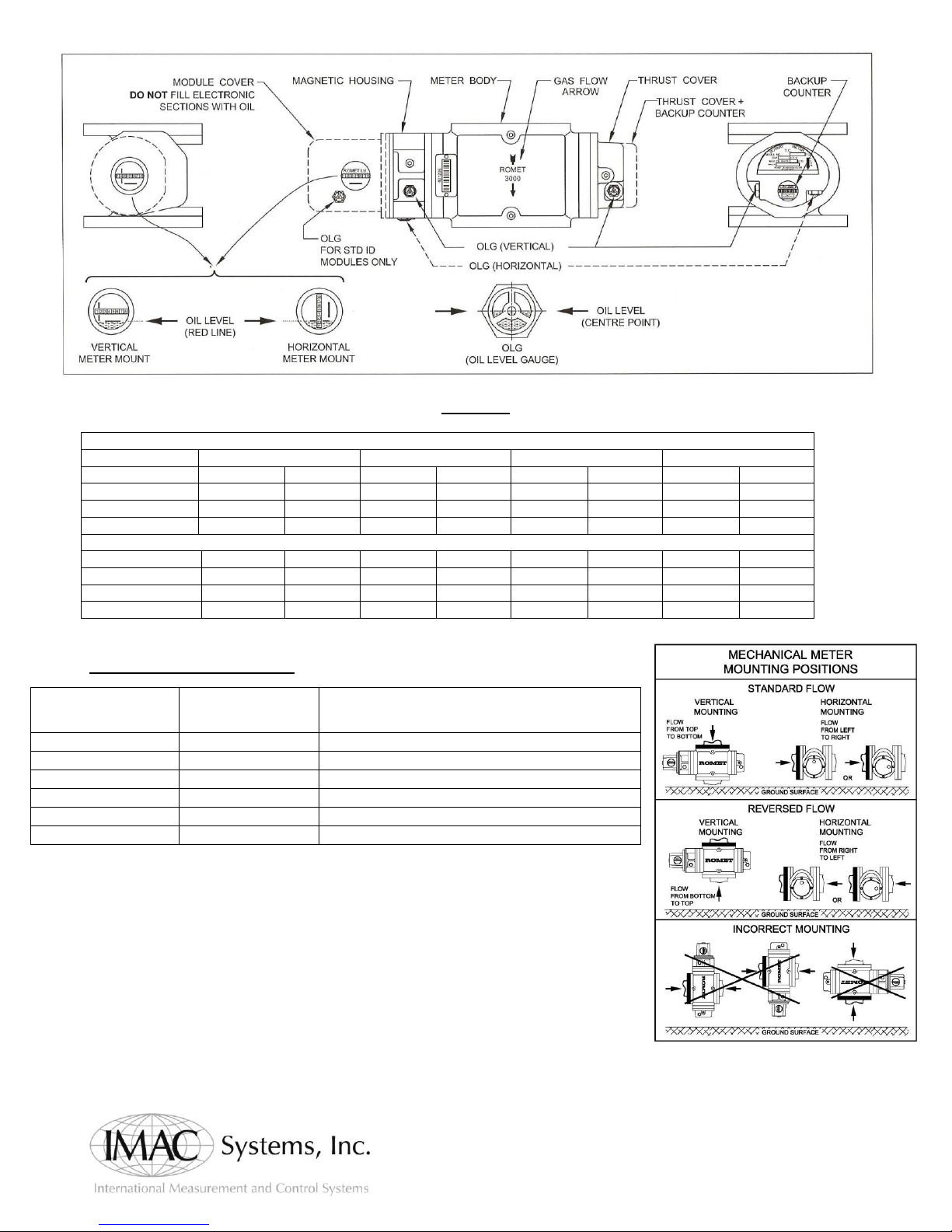
•Mount the meter in correct orientation. Ensure that gas will
be flowing in the direction of the arrow on meter pressure
body (see diagram 1). Meters should be installed using
hardware sizes listed in diagram 2. The use of incorrect
hardware may result in meter error or failure. All bolts should
be tightened in an X pattern, in stages, up to a typical torque
value of 20 ft lbs. Some Romet meters are supplied with
nippled connections at the inlet and outlet. These meters are
built and tested with the connecting nipples in place. Care
must be taken to avoid further tightening or loosening of thee
nipples to prevent meter damage.
•After the meter has been installed, approved meter oil must
be added to all appropriate oil reservoirs to prevent meter
damage. Depending on the meter type and mounting position
(vertical or horizontal) the required oil volumes will be
different. Do not over or under-fill oil reservoirs. For the
thrust cover end and all the magnetic housing (not on all
meter types) oil must be added so that the oil reaches the
center of the correct oil level gauge (OLG) in use. For the
module cover, the oil must reach the appropriate Red oil level
line. DO NOT FILL ELECTRONIC SECTIONS WITH OIL.
Note: After meter start up, some oil levels may drop a little or
form a thing bubble layer due to oil splash. Do not mix oil
types.
•Ensure all oil plugs (and other connections) are properly
tightened and secured before pressurizing the meter set.
•When the meter installation has been completed the meter set
should be pressurized SLOWLY (maximum 5 psi per second)
up to allowable pressure. This will help avoid over-speed or
slamming of the meter. Should the installation be subject to
sudden “Instant On-Off” loads, a properly sized restricting
orifice or venture flow nozzle should be installed
•Check for any gas leaks or other possible problems.
After start up, the readout counter or drive should be running
smoothly and in the correct direction when the required gas
flow rate has been reached.
This bulletin covers the general installation of all Romet Rotary Meters
•Pete’s Plugs may be installed to facilitate future oil changes while meter is pressurized. Other optional accessories & services are
available such as strainers, gaskets, valves Teflon tape, flange kits, meter flow reverse, meter repair, and more.
RM600-RM56000
Tel: 800 955-4Gas ● 215 946-2200 Fax: 215 943-2984
90 Main Street ● PO Box 1605 ● Tullytown, PA. 19007
www.imacsystems.com ● sales@imacsystems.com
Standard Counter & Instrument Drive
RM600-RM1500
RM2000-RM5000
RM7000-RM23000
RM25000-RM56000
Horizontal
Vertical
Horizontal
Vertical
Horizontal
Vertical
Horizontal
Vertical
Counter Module
6.3 oz.
6.3 oz.
6.3 oz.
6.3 oz.
6.3 oz.
6.3 oz.
6.3 oz.
6.3 oz.
Magnet Housing
1.8 oz.
1.8 oz.
2.3 oz.
3.5 oz.
3.5 oz.
11.6 oz.
10.5 oz.
32.4 oz.
Thrust End
0.9 oz.
2.1 oz.
0.9 oz.
2.5 oz.
1.4 oz.
8.8 oz.
10.5 oz.
38.2 oz.
Temperature Compensated & Temperature Compensated Instrument Drive
Horizontal
Vertical
Horizontal
Vertical
Horizontal
Vertical
Horizontal
Vertical
Counter Module
n/a
n/a
5.6 oz.
8.8 oz.
8.4 oz.
20.8 oz.
n/a
n/a
Magnet Housing
n/a
n/a
2.3 oz.
3.5 oz.
3.5 oz.
11.6 oz.
n/a
n/a
Thrust End
n/a
n/a
0.9 oz.
2.5 oz.
1.4 oz.
8.8 oz.
n/a
n/a
Meter Model
Flange/Gasket
(Full-Face)
Bolts and washers (Steel, Zinc Plated or
PTFE Coated)
RM600-RM1500
1.5” NPT Threaded
N/A
RM1000-RM1500
ANSI 125/150 2”
5/8” – 11 x 1.5” long Hex Head SAE Grade 5
RM2000-RM3000
ANSI 125/150 2”
5/8” – 11 x 1.75” long Hex Head SAE Grade 5
RM5000-RM7000
ANSI 125/150 3”
5/8” – 11 x 1.75” long Hex Head SAE Grade 5
RM11000-RM23000
ANSI 125/150 4”
5/8” – 11 x 1.75” long Hex Head SAE Grade 5
RM25000-RM56000
ANSI 125/150 6”
3/4” – 10 x 2.5” long Hex Head SAE Grade 5
Oil Table:
*ECM2 Series and AdEM Series modules being electronic do not require oil.
Hardware Specification Table:
*All bolts should be installed with approved anti-seize grease and standard steel zinc plate flat washers.
*To install in meter in a reversed flow
configuration, flow configuration
must be switched by factory*
______________________________________________________________________________________________________________
Tel: 800 955-4Gas ● 215 946-2200 Fax: 215 943-2984
90 Main Street ● PO Box 1605 ● Tullytown, PA. 19007
www.imacsystems.com ● sales@imacsystems.com
 Loading...