

Imac NGS 1000 Installation, Operation & Maintenance Instructions Manual
IMAC Systems, Inc.
90 Main Street, PO Box 1605
Tullytown, PA 19007
1-800-955-4GAS
Phone: (215) 946-2200
Fax: (215) 943-2984
sales@imacsystems.com
INSTALLATION, OPERATION & MAINTENANCE INSTRUCTIONS FOR
NGS 1000 NATURAL GAS SCRUBBERS
10 AND 25 SCFM UNITS
10001000
Natural Gas Scrubber
NEW
PRODUCT
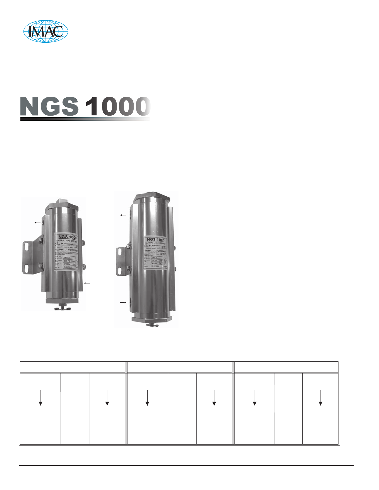
NGS-4
10 SCFM
Outlet
Outlet
Inlet
NGS-12
25 SCFM
APPLICATION
Designed specifically for industrial applications with natural gas
supply lines such as:
· Cata-Dyne™ Series MKII, WX, and BX heaters
· Enclosure systems
· Instrument gas pre-heaters
STANDARD PRODUCT FEATURES
· CRN Certified (#0H6573.213) to 250 psi and 200°F
· Two sizes available
SIZE 4, 10 SCFM, ؼ” NPT
SIZE 12, 25 SCFM , Ø ¾” NPT
MOUNTING OPTIONS
With appropriate brackets, the NGS 1000 natural gas scrubber can
be installed in an existing piping system or it can be bolted to a
wall/panel using the factory supplied stainless steel wall mounting
kit.
FEATURES
CRN CERTIFIED #0H6573.213
Max. Pressure = 250 psi
Max. Temperature = 200°F
Min. Temperature = -40°F
Flow Rates: 10 SCFM to 25 SCFM
SAE/ORB o-ring design.
Inlet
Figure 1. NGS 1000
Natural Gas Scrubber
Two sizes available NGS-4 and NGS-12
Table 1. Natural Gas Scrubber, Cartridge, and Mounting Kit Coded Numbering System.
BENEFITS
Extend the life of your Cata-Dyne™ infrared heater if sour gas or
moisture is present.
Low-pressure drop at rated flow.
Gas Scrubber Cartridge Mounting Kit
NGSNGS NGC- - -4 4 K
Natural Gas
Scrubber
4 = 10 SCFM
12 = 25 SCFM
Natural Gas
Cartridge
4 = 10 SCFM
12 = 25 SCFM
Natural Gas
Scrubber
A Leader in Advanced Heating Solutions
K = Mounting
Kit
INSTALLATION & MAINTENANCE INSTRUCTIONS
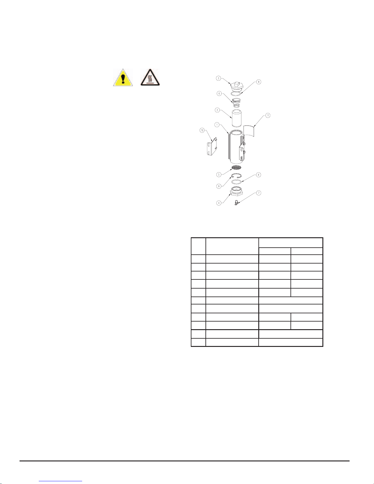
ITEM DESCRIPTION
NGS-4* NGS-12*
1 SCRUBBER HOUSING B16135-01 B16138-01
2 CARTRIDGE NGC-4 NGC-12
3 THREADED COVER B16142-01 B16143-01
4 THREADED BASE B16142-02 B16143-02
5 BAFFLE A16146-01 A16146-02
6 CONICAL SPRING
7 DRAIN COCK
8 ORING A10069-42 A10069-43
9 SNAP RING A16154-01 A16154-02
10 MOUNTING BRACKET
11 LABEL
PART NUMBER
B16158-01
NGS-K
A16150-01
A16149-01
WARNINGS
NGS 1000
Natural Gas Scrubbers
1. Read and follow all instructions contained in this manual before
installing, operating, and maintaining this equipment. Failure to
do so could void the warranty, damage the equipment, or cause
severe injury or death.
2. Relieve all pressure before dismantling unit.
NGC - Cartridges
1. Do not use cartridge if the package has been damaged or seal is
broken.
2. Store cartridges at room temperature in a dry/dark place.
3. Avoid contact with eyes or exposed skin.
4. Contents may be harmful if swallowed or inhaled as dust.
5. Spilled or discarded product should be disposed of in accordance
with all applicable government regulations.
6. Contents may become hot if exposed to water.
HOW TO ORDER
Natural Gas Scrubber cartridge and mounting kit coded numbering system
is presented in Table 1, while the parts list is in Table 2.
INSTRUCTIONS
INSTALLATION PROCEDURE
A. Read and follow all instructions contained in this manual before
installing, operating, and maintaining this equipment. Failure to do so
could void the warranty, damage the equipment, or cause severe injury
or death.
Figure 2. NGS 1000 Gas Scrubber and NGC Cartridge
Table 2. Parts List
B. Review Figure 2 for NGS 1000 scrubber component nomenclature.
Refer to Figure 3 for mounting dimensions and NGS scrubber general
arrangement. Install scrubber units only in vertical position shown.
C. Install the NGS 1000 scrubber using appropriate mounting hardware.
Optional (factory supplied) universal mounting brackets are available.
D. Relieve and block all pressure before installing, maintaining, or
dismantling the NGS 1000 scrubber.
E. Remove the NGS 1000 scrubber cover (Item 3). Carefully inspect the
spring (item 6), the o-ring (item 8), and the cover/housing threads.
Remove any dirt, contaminants, or residue from the cover/housing
threads prior to final assembly.
F. Read the label on the NGC Natural Gas Cartridge (Item 1) then remove
the cartridge from the factory-sealed bag. Ensure the contents of the
NGC cartridge are never exposed to water.
G. Insert the NGC cartridge (Item 1) into the scrubber housing (Item 2).
To help with this process you may choose to insert a sheet of rolled
paper or transparency into the scrubber housing (Item 2) prior to
inserting the NGC cartridge. Remember to remove the paper or
transparency once the NGC cartridge has been installed.
H. Re-install the NGS cover (Item 3) using a wrench (see Table 3(b) for
hex size) and ensure the cover has completely bottomed out and there
is zero gap between the cover and the housing. CAUTION: DO NOT
OVERTIGHTEN the cover or thread damage may occur. Contact
the factory if threads are damaged, corroded, stripped, or galled.
I. Ensure all fittings are installed and sealed in accordance with the
manufacturer's specifications.
J. Verify that the drain cock (Item 7) is in the fully closed position
(clockwise hand tight) before pressurizing the system.
A Leader in Advanced Heating Solutions
* ADD SUFFIX-G FOR Ø1/8” NPT GAUGE PORT OPTION
MAINTENANCE PROCEDURE
I. Refer to Table 4 to determine the suggested change-out
frequency for your Cata-Dyne™ heater application.
II. Relieve and block all pressure before installing, maintaining,
or dismantling the NGS 1000 scrubber.
III. Release and contain any residual water/ contaminates from the
drain bowl by opening the drain cock (Item 7) counterclockwise.
IV. Repeat step E of the Installation Instructions.
V. Remove and properly dispose of used or contaminated cartridges
in accordance with all applicable government regulations.
VI. Repeat steps F through J of the Installation Instructions.
 Loading...