

Page 1
SI-2 System Integrator
Installation guide
SI-2-NA
Page 2

Page 3

P1
Contents
Introduction 2
Welcome 2
Supplied parts 2
Dimensions 2
Ambient atmosphere requirements 2
Connections 3
iCANnet wiring 3
iCANnet announce button 3
iCANnet termination 3
Serial device connection 4
Operation indicators 4
Programming 5
Adding the SI-2 to iCANsoft 5
The SI-2 conguration window 5
Viewing SI-2 details in iCANsoft 5
RS232 communication settings 6
Startup action 7
Input strings 8
Input actions 9
Output strings 10
Output actions 11
Sequences 12
Diagnostics 13
Appendix 1 14
ASCII Virtual Control Messages 14
Page 4
P2
Introduction
Welcome
The SI-2 System Integrator provides a vital link point
between any iCANnet network and a third party device
such as an audio visual unit. The compact SI-2 System
Integrator provides a 5-way connector block at one end
for the iCANnet link and a 9-pin D-type female socket
at the other end for the RS232 serial connection to the
third party device.
Using the intuitive iCANsoft application, you can program the SI-2 to search for particular actions or messages received from other control units attached to the
iCANnet network. When a received action or message
matches a stored template, the SI-2 will send a control
message to the device connected via the serial port.
Similarly, the SI-2 also monitors messages being sent
back from the connected serial device and when any of
those messages match those stored within its memory,
a range of actions can be triggered on the iCANnet
network.
The SI-2 System Integrator can store up to 100 input
and output messages together with their related actions.
Additionally, the SI-2 can store up to 16 sequences,
each of which can comprise up to 128 separate steps to
allow multiple actions to be triggered by a single command.
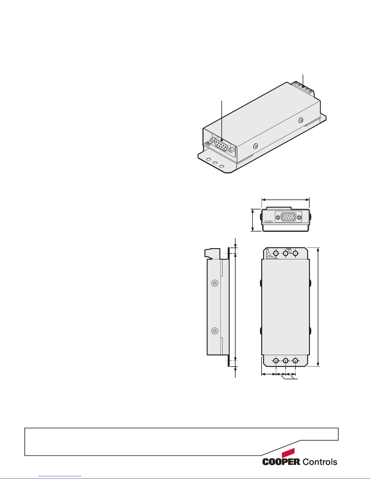
Supplied parts
Serial connection
to device
Dimensions
iCANnet connection
to network
Ambient atmosphere requirements
Temperature 00C to +400C (320F to 1040F)
Humidity 0 to 95% non-condensing
1.97 in.
(50 mm)
0.6 in.
(15 mm)
0.4 in.
(10 mm)
0.9 in.
(23 mm)
4.88 in.
(124 mm)
4.40 in.
(112 mm)
0.24 in.
(6 mm)
0.24 in.
(6 mm)
Note: All mounting
holes are 4mm (0.15
in.) diameter. The two
outer holes at either
end allow you to
attach the unit using
plastic ties.
Page 5
P3
Cable type: Cooper LC or CAT 5
Maximum cable length: 1000 ft. (305 m) *
Devices per segment: 100 (without bridge or repeater)
Connections
iCANnet wiring
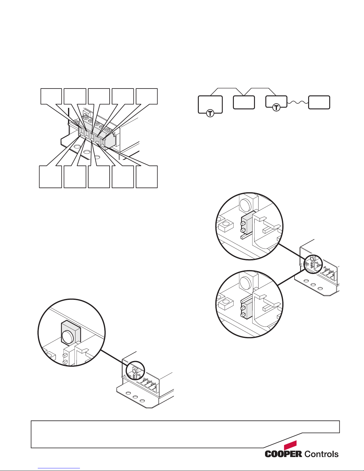
Cable connections to the iCANnet network are made to
a removable 5-way connector block located at one end
of the SI-2 unit:
Termination off
Termination on
iCANnet termination
The iCANnet link is a ‘daisy chain’ protocol that requires
termination on the devices located at either end of the
iCANnet chain.
The SI-2 unit is supplied with termination enabled as
standard. If it is not connected as an end device in the
iCANnet chain, you need to disable termination.
Note: The connection to the serial device is treated
separately and has no impact on whether or not the SI-2
should be terminated.
To disable SI-2 termination, move the jumper from the
lower two pins to the upper two pins, as shown here:
iCAN
Device
iCAN
Device
Serial
Device
SI-2
iCANnet announce button
The SI-2 unit features a small button adjacent to the
green connector which can be used to add the device to
an iCANnet network. When pressed, the SI-2 will send
an announcement message across the iCANnet network. Please see the section ‘Adding the SI-2 to
iCANsoft’ for more details.
0V
(black)
0V
(Green
pair)
CAN-L
(blue)
CAN-L
(Blue)
DRAIN
(gray)
DRAIN
(Brown
pair)
+12V
(red)
+12V
(orange
pair)
CAN-H
(white)
CAN-H
(Blue/
white)
Cooper
LC cable
CAT 5
cable
* A maximum segment distance of 3200 ft. (1000 m) is possible if an
additional 12V power supply is used.
Page 6
P4
Serial device connection
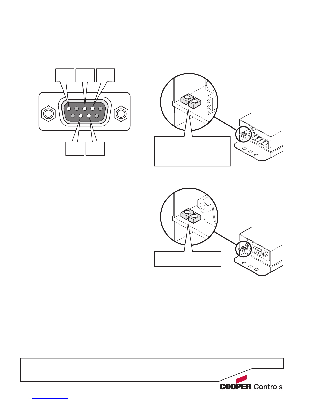
The SI-2 unit provides an RS232 link via a standard 9-
pin D-type female connector. The SI-2 uses ve pins of
the D-type connector as shown below:
The various serial communication parameters used by
the SI-2 serial port are all fully congurable using the
iCANsoft application:
Baud rate 1200, 2400, 4800, 9600, 19200,
38400, 57600 or 115200
Data bits 7 or 8
Stop bits 1 or 2
Parity None, Reserved, Even or Odd
Handshaking Enabled or Disabled
TxD
(pin 2)
RxD
(pin 3)
CTS
(pin 7)
GND
(pin 5)
RTS
(pin 8)
Operation indicators
The SI-2 unit has a red and green indicator at either end
to assist with conguration and troubleshooting.
At the iCANnet end
At the RS232 end
Green: RS232 data received
Red: RS232 data sent
Green ashing: Normal operation
Red ashing: Trafc being sent
and/or received
Red on: CANbus error
Page 7
P5
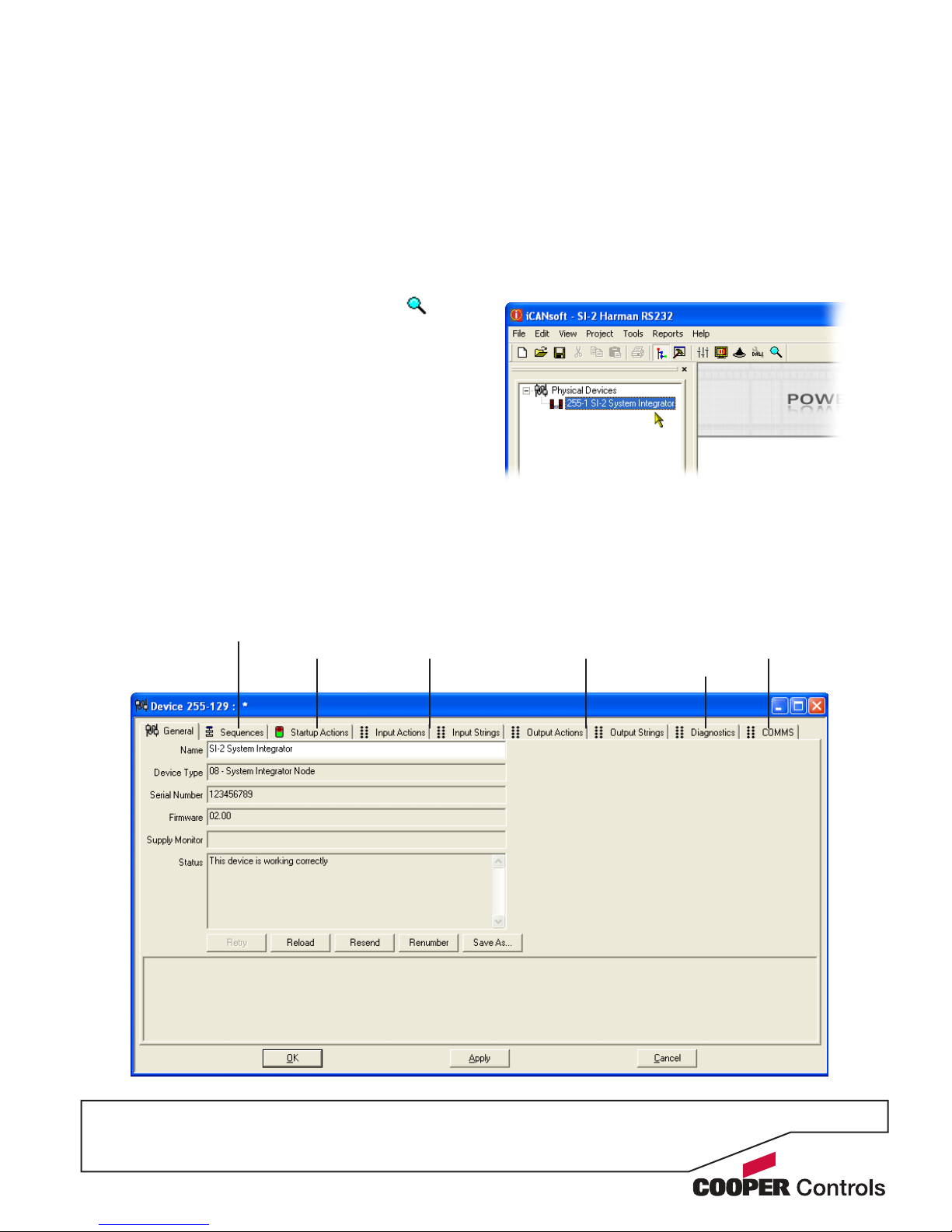
Viewing SI-2 details in iCANsoft
Once the SI-2 unit has been added to the iCANsoft
application, it will appear in the devices list within the
Workspace window:
Programming
This section provides details about programming items
specic to the SI-2 system integrator within the
iCANsoft application. For details about the general use
of iCANsoft, please refer to the System manual.
Adding the SI-2 to iCANsoft
Once the SI-2 System Integrator has been connected
to the iCANnet network, you can add it to the iCANsoft
application in any of the following three ways:
• Within the iCANsoft main window, click the icon,
• Within the iCANsoft main window, select ‘Tools’ >
‘Advanced Network Search’, or
• On the SI-2 unit, adjacent to the green connector
block, press and release the small button to cause
an announcement message to be sent across the
network.
Note: Where there are multiple SI-2 units installed
on a network, you can use the announce button to
pinpoint the device within iCANsoft. Its entry within
the device list will appear in bold and the iCANsoft
output section will provide device number details.
To view the conguration window for the SI-2 system
integrator, double click its entry within the list.
The SI-2 conguration window
This tabbed window provides all of the options necessary to program the SI-2 unit.
Output Actions
and Strings
Input Actions
and Strings
Startup
Actions
Sequences
Diagnostics
Communication
settings
Page 8
P6
RS232 communication settings
Before the SI-2 system integrator can successfully communicate with the device to which it is connected, you
must ensure that the RS232 communication settings
of the device match those of the SI-2 unit. For details
about discovering or changing the communication settings for the connected device, please refer to documentation supplied with it.
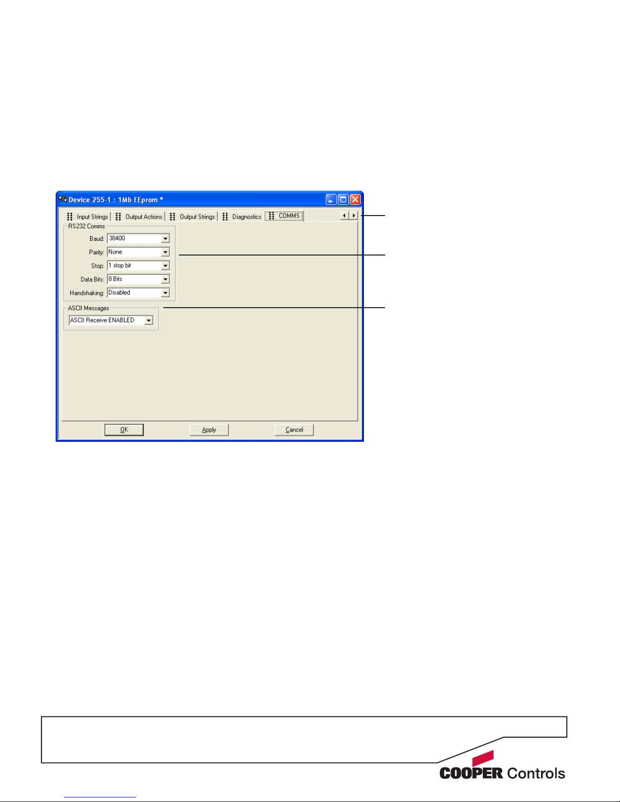
To adjust SI-2 unit communication settings
1 Click on the ‘COMMS’ tab to display the following
page:
Note: The ‘COMMS’ tab is the furthest right of all
the tabs, you may need to use the horizontal scroll
buttons in the top right corner to reveal the tab if the
window size is limited.
2 Use the options within the ‘RS232 Comms’ section
to select the appropriate settings that match those
used by the connected device.
3 Optionally, change the ‘ASCII Messages’ section to
determine how special ‘Virtual Control Messages’ are
transferred across the SI-2. Please refer to Appendix
1 for more details about Virtual Control Messages.
4 When all settings have been made, either click the
Apply button to save without closing the window or
click the OK button to save and close.
Use this section to ensure that the SI-2
communication settings match those of
the connected device.
This option determines how the SI-2
should deal with Virtual Control Messages.
These are system level control messages,
as opposed to your custom message
strings which operate at device level. The
SI-2 passes these special ASCII virtual
control messages unchanged between the
iCANnet network and the RS232 serial port
according to the setting of this option.
Note: The setting of this option does not
affect the transfer of standard custom
message strings.
ASCII Messages DISABLED - Prevents
any transfer of virtual control messages
through the SI-2.
ASCII Receive ENABLED - Allows virtual
control messages to ow only from the
RS232 serial link to the iCANnet network.
ASCII Transmit ENABLED - Allows virtual
control messages to ow only from the
iCANnet network to the RS232 serial link.
Rx/Tx both ENABLED - Permits free ow
of virtual control messages between the
iCANnet and the RS232 serial port.
Scroll buttons - if the main window size
does not allow all tabs to be displayed at
once, use these buttons to reveal hidden
tabs.
Page 9
P7
Startup action
The Startup Actions tab allows you to optionally arrange
for a particular action to be instigated every time that the
SI-2 unit is powered on.
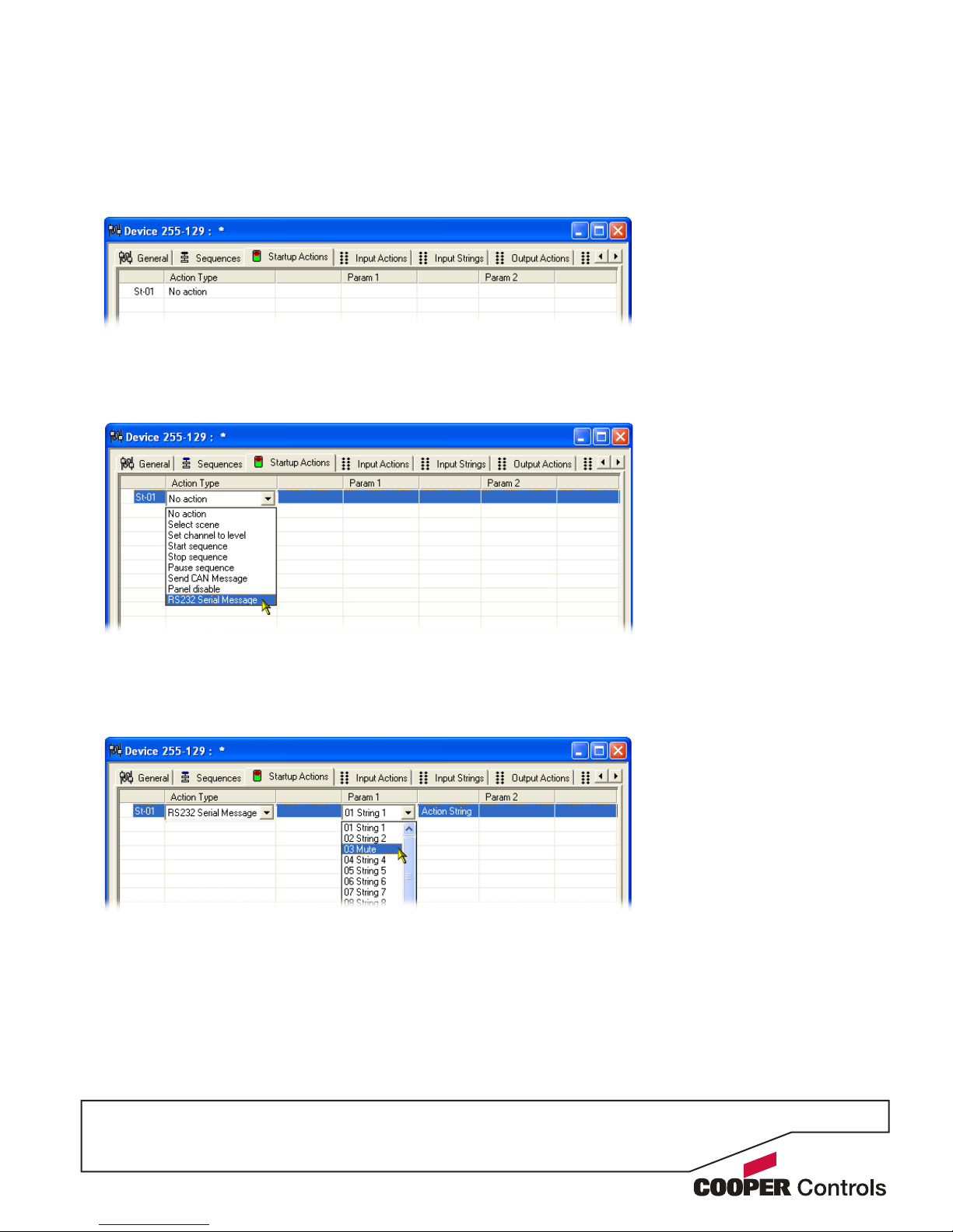
To choose a startup action
1 Click on the ‘Startup Actions’ tab to display the
following page:
2 Click on the rst entry to highlight it and also to show
selection box for the ‘Action Type’ column. Click
on the ‘Action Type’ down arrow to reveal the list of
available options:
3 Select the required action type. Depending upon the
chosen action, one or more of the ‘Param’ columns
to the right will show their own selection options. You
can use these to further dene the action that should
occur during the SI-2 startup phase.
Note: When selecting the RS232 Serial Message
option, the available output message strings can be
viewed and altered within the ‘Output Strings’ tab.
4 When all settings have been made, either click the
Apply button to save without closing the window or
click the OK button to save and close.
Page 10
P8
Input strings
The ‘Input Strings’ tab is where you can dene the messages that you expect to receive from the connected
device. Once dened, you can then use the related
‘Input Actions’ page to determine what action the SI-2
should take when any particular message is received.
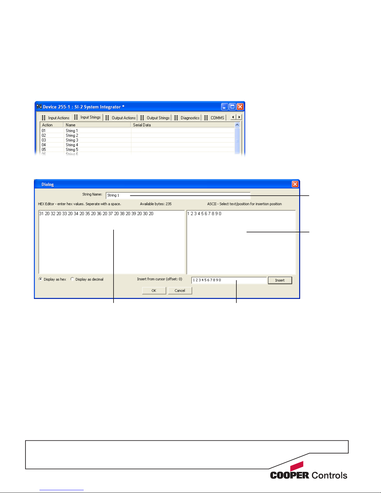
To dene or alter an input string
1 Click on the ‘Input Strings’ tab to display the
following page:
2 Double click the required entry to display the
following edit dialog box:
3 Using either the HEX editor area on the left or the
‘Insert from cursor’ eld on the right, enter or edit the
message string, as necessary.
4 When the message is complete, click the OK button
to return to the ‘Input Strings’ page.
5 Within the ‘Input Strings’ page, you can enter/edit
all other required strings and, when all settings have
been made, either click the Apply button to save
without closing the window or click the OK button to
save and close.
Enter the string (in ASCII) here and then
click the Insert button.
ASCII area This area shows
the current
message string
as ASCII
characters.
HEX editor area - This area shows the current message string either in hexadecimal
or decimal notation, depending on the
setting in the lower left corner.
String name You can edit the
title of the string
here.
Page 11
P9
Input actions
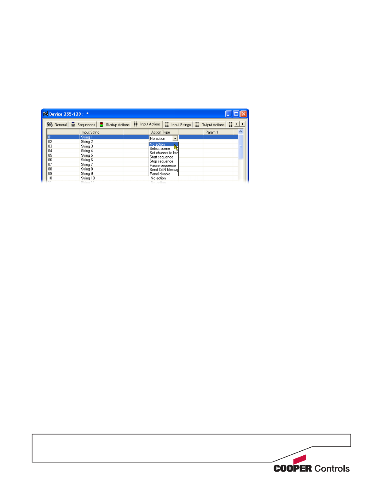
The ‘Input Actions’ tab allows you to determine what
should occur when a received message from the con-
nected device matches one of those dened within the
‘Input Strings’ page.
To dene or alter an input action
1 Click on the ‘Input Actions’ tab.
2 Click on the required entry to highlight it and then
click on the ‘Action Type’ down arrow to reveal the
available actions:
3 Select the required action. Depending upon the
chosen action, one or more of the ‘Param’ columns
to the right will show their own selection options.
You can use these to further dene the action that
should occur whenever the related message string is
received from the connected device.
4 Edit all other required actions and, when all settings
have been made, either click the Apply button to
save without closing the window or click the OK button to save and close.
Page 12
P10
Output strings
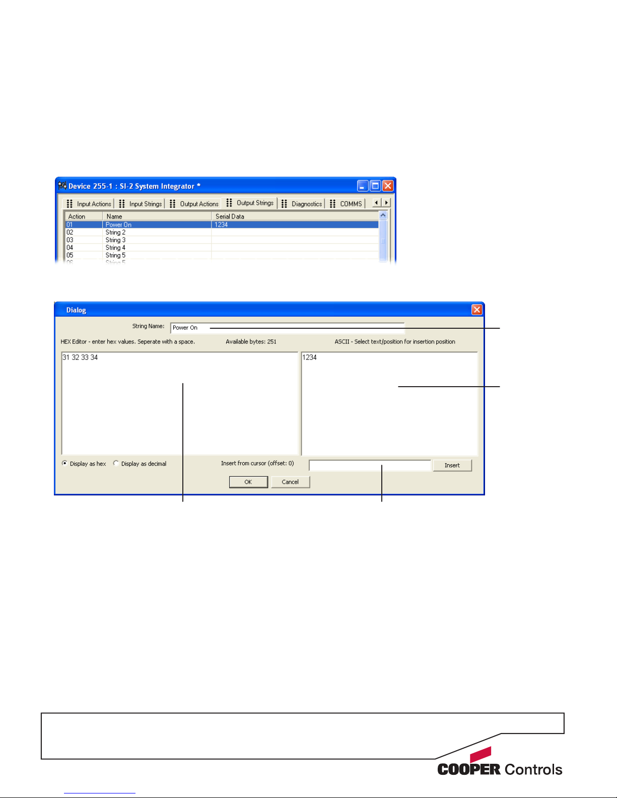
The ‘Output Strings’ tab is where you can dene one
or more message strings that need to be sent to the
connected device, when prompted by certain iCANnet
actions. Once dened, you can then use the related
‘Output Actions’ page to link iCANnet actions to the
dened string message(s).
To dene or alter an output string
1 Click on the ‘Output Strings’ tab to display the
following page:
2 Double click the required entry to display the
following edit dialog box:
3 Using either the HEX editor area on the left or the
‘Insert from cursor’ eld on the right, enter or edit the
message string, as necessary.
4 When the message is complete, click the OK button
to return to the ‘Output Strings’ page.
5 Within the ‘Output Strings’ page, you can enter/edit
all other required strings and, when all settings have
been made, either click the Apply button to save
without closing the window or click the OK button to
save and close.
Enter the string (in ASCII) here and then
click the Insert button.
ASCII area This area shows
the current
message string
as ASCII
characters.
HEX editor area - This area shows the current message string either in hexadecimal
or decimal notation, depending on the
setting in the lower left corner.
String name You can edit the
title of the string
here.
Page 13
P11
Output actions
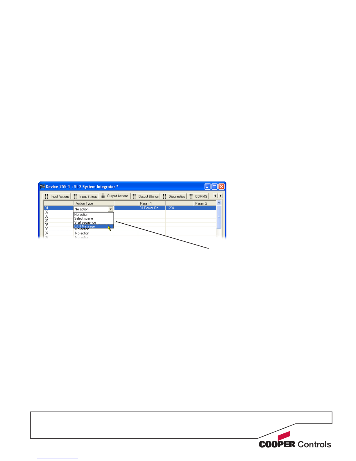
The ‘Output Actions’ tab allows you to link an action
received via the iCANnet network, to a message string
that will be sent to a connected device. Depending on
the selected iCANnet ‘Action Type’ within this page, a
number of parameters will become available to allow
you to fully dene the iCANnet action. In operation,
when a received iCANnet action then matches the pa-
rameters dened within this page, the SI-2 unit will send
the message string (from the Output Strings page) that
corresponds to the row number (01, 02, 03, etc.) of the
matched action on this page.
Note: Ensure that the action type and parameters selected here exactly match those that are expected from the
iCANnet network, otherwise the related string messages
will not be sent.
To dene or alter an output action
1 Click on the ‘Output Actions’ tab.
2 Click on the required entry to highlight it and then
click on the ‘Action Type’ down arrow to reveal the
available actions:
3 Select the required ‘Action Type’. Depending upon
the chosen action, one or more of the ‘Param’
columns to the right will show their own selection
options. You can use these to further dene the
iCANnet action that will be used to trigger the message string.
4 Edit all other required actions and, when all settings
have been made, either click the Apply button to
save without closing the window or click the OK button to save and close.
Action types
Select scene - Allows you to select an area
and choose a particular scene within that
area which will trigger an output action.
Start sequence - Allows you to dene a
sequence number, and optionally a particular
step within that sequence, which will trigger
an output action.
Note: Sequence numbers from 1 to 16
coincide with sequences that may be programmed within the SI-2 unit itself. If a
sequence number below 17 is monitored to
cause an output action and is also used as an
SI-2-contained sequence, then both events
will take place simultaneously. To avoid any
confusion is it suggested that sequence
numbers of 17 or over are monitored, if dual
actions are not required.
CAN Message - Allows you to dene the ex-
act CAN message (from any iCANnet device)
that will trigger an output action.
Page 14
P12
Sequences
Sequences allow you to link a number of individual
actions together, with or without a time delay between
each, in order to cause multiple operations from a single
trigger action. The SI-2 can store up to sixteen sequences of its own (each with up to 128 steps) that can be
triggered by an action via the iCANnet network.
Note: Sequence numbers monitored from 1 to 16 within
the ‘Output Actions’ page coincide with the sequences
that may be programmed within the SI-2 unit itself. If a
sequence number below 17 is monitored to cause an
output action and is also used as an SI-2-contained sequence, then both events will take place simultaneously.
To dene a sequence
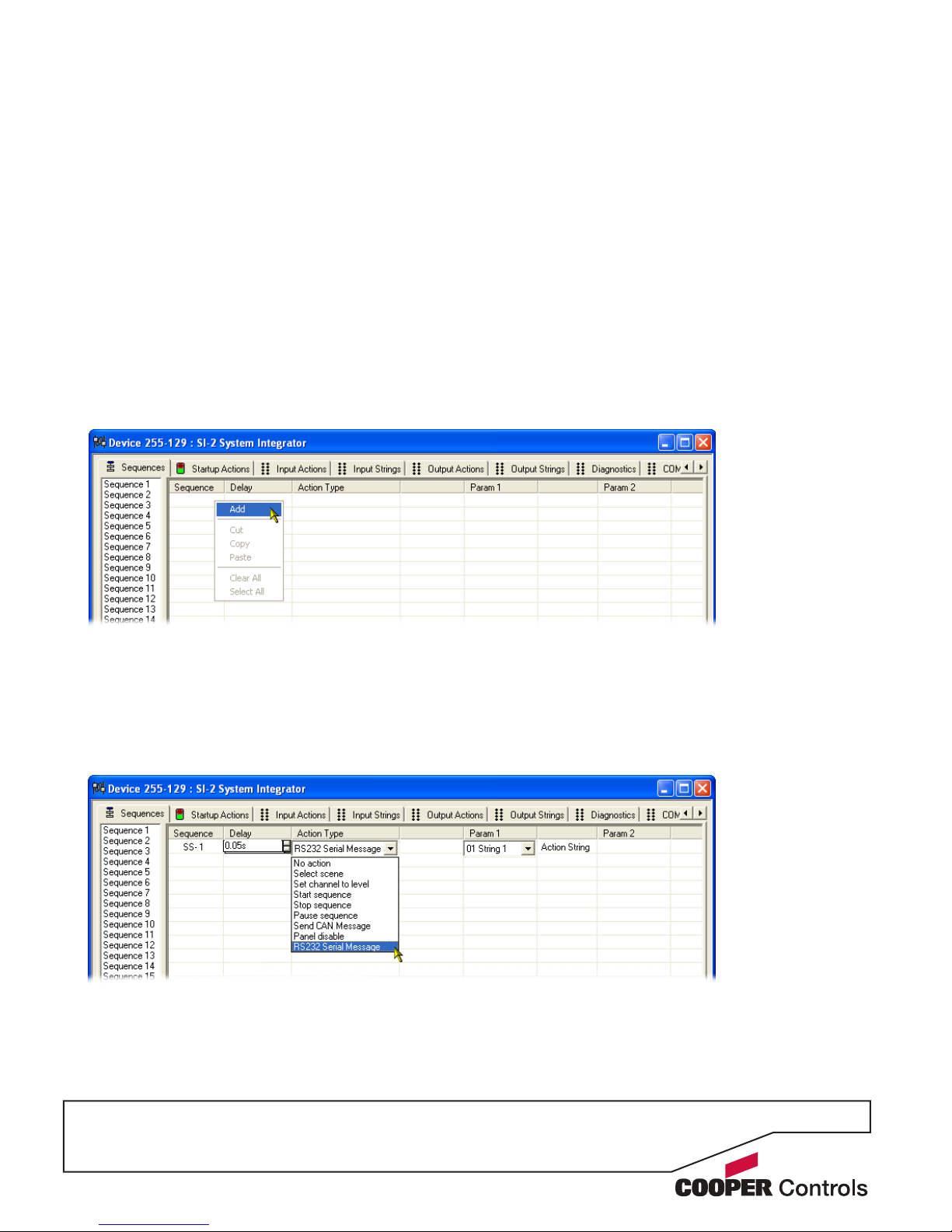
1 Click on the ‘Sequences’ tab to display the page.
2 Right click within the main panel area to display a
popup menu. Select the ‘Add’ option to add a step
to the sequence.
3 Optionally alter the delay option (introduces a time
delay before the current action is launched).
4 Click the ‘Action Type’ down arrow and select the
required action form the list. Depending upon the
chosen action, one or more of the ‘Param’ columns
to the right will show their own selection options. You
can use these to further dene the selected action.
5 Repeat steps 2 to 4 for each required step within
the sequence. When all have been congured, either
click the Apply button to save without closing the
window or click the OK button to save and close.
Page 15

P13
Diagnostics
The Diagnostics page provides tools for testing all aspects of your SI-2 installation. The page is split into six
separate areas as shown here:
Input Actions - allows you to
simulate an incoming message
from the serial device in order
to trigger the associated actions on the iCANnet network.
Output Actions - allows you
to simulate an action from the
iCANnet network in order to cause
a programmed output string to be
sent to the serial device.
Output Strings - allows you to
send any of the programmed
output strings to the serial
device independently of the
triggering iCANnet action.
Startup Action
- launches the action
that has been congured to run at every
SI-2 unit power up.
Sequence Tests - allows you
to start, stop and pause any
of the sequences that are programmed within the SI-2 unit.
Sequence Steps - displays
the individual steps contained
within the sequence selected
on the left.
Note: Test buttons shown with darker backgrounds and
red text indicate that no action or string is associated for
that particular entry.
Page 16
P14
Appendix 1
ASCII virtual control messages
Command RE Report Current Scene
This message reports the current scene number in an
area.
The syntax is: @RExxx:Axxx<cr>
RExxx defines the Scene Number, valid for 0 to 999.
Axxx defines the Area Number, valid for 1 to 999.
Command SC Set Channel Level
This message sets the level of a channel in an area.
The syntax is: @SCxxx:Axxx:Lxx:Fxxx<cr>
SCxxx defines the channel number, where xxx is valid
from 0 to 999. Channel 0 affects ALL channels in an
area.
Axxx defines the Area Number, valid for 1 to 999.
Lxx defines the Level, valid for 0 to 99 in %, and FF for
FULL (100%)
Fxxx defines the Fade Time, valid for 0 to 999 for seconds.
Start
character
@SS12:A23:F145<cr>
Select
scene 12
Select
area 23
145 second
fade
End Character.
Message terminated
with a carriage return
character typically
hex D, decimal 13
or #
In addition to translating customised commands and messages
between the iCANnet network and
an RS232 device, the SI-2 can
convert Virtual Control Messages
between the network and the connected device.
Virtual control messages are used
to control the system as whole, not
individual devices. These message
conversions are hard coded into
the SI-2 unit and do not occupy
any of the memory spaces reserved for customised commands.
This section provides an overview
of the supported virtual control
messages.
The general command syntax for virtual control messages is shown here:
Command SS Select Scene
This message selects a scene in an area.
The syntax is: @SSxxx:Axxx:Fxxx<cr>
SSxxx defines the scene number, where xxx is valid from
0 to 999. Scene 0 is OFF.
Axxx defines the Area Number, valid for 1 to 999.
Fxxx defines the Fade Time, valid for 0 to 999 for seconds.
Command SA Save Scene
This message saves the current levels to a scene in an
area.
The syntax is: @SAxxx:Axxx<cr>
SAxxx defines the scene number, where xxx is valid from
0 to 999 - Scene 0 saves to the current scene.
Axxx defines the Area Number, valid for 0 to 999.
Command RS Request Current Scene
This message requests the current scene number in an
area.
The syntax is: @RSxxx<cr>
RSxxx defines the Area Number, valid for 1 to 999.
Page 17

P15
Command RC Request Channel Level
This message requests the level of a channel in an area.
The syntax is: @RCxxx:Axxx<cr>
RCxxx defines the channel number, where xxx is valid
from 0 to 999. Channel 0 requests ALL channels in an
area (use with caution).
Axxx defines the Area Number, valid for 1 to 999.
Command RL Report Channel Level
This message reports the current level of a channel in an
area.
The syntax is: @RLxxx:Axxx:Lxx<cr>
RLxxx defines the Channel Number, valid for 1 to 999.
Axxx defines the Area Number, valid for 1 to 999.
Lxx defines the Level, valid for 0 to 99 in %, and FF for
FULL (100%).
Command CR Raise
This message increments the area by 1% level
The syntax is: @CRxxx:Axxx <cr>
CRxxx defines the channel number, where xxx is valid
from 0 to 99. Channel 0 affects ALL channels in an area.
Axxx defines the Area Number, valid for 1 to 999.
Command CL Lower
This message decrements the area by 1% level
The syntax is: @CLxxx:Axxx <cr>
CLxxx denes the channel number, where xxx is valid
from 0 to 999. Channel 0 affects ALL channels in an
area.
Axxx denes the Area Number, valid for 1 to 999.
Command SF Stop Fade
This message stops fading in an area.
The syntax is: @SFxxx:Axxx <cr>
SFxxx defines the channel number, where xxx is valid
from 0 to 999. Channel 0 affects ALL channels in an
area.
Axxx defines the Area Number, valid for 1 to 999.
Command QS Start Sequence
This message initiates a selected sequence.
The syntax is: @QSxx:Sxxx:Nxxx:Axxx<cr>
QSxx defines the sequence number, where xx is 1 to 16.
Sxxx defines the segment number where xxx is 1 to 255.
Nxxx defines the node number where xxx is 1 to 255.
Axxx defines the action (step) number where xxx
is 0 to 128.
Command QP Pause Sequence
This message pauses a selected sequence.
The syntax is: @QPxx:Sxxx:Nxxx<cr>
QPxx defines the sequence number, where xx is 1 to 16.
Sxxx defines the segment number where xxx is 1 to 255.
Nxxx defines the node number where xxx is 1 to 255.
Command QT Stop Sequence
This message halts a selected sequence.
The syntax is: @QTxx:Sxxx:Nxxx<cr>
QTxx defines the sequence number, where xx is 1 to 16.
Sxxx defines the segment number where xxx is 1 to 255.
Nxxx defines the node number where xxx is 1 to 255.
Page 18

Document 73-891-00 IM8527 Iss.03
All products manufactured by Cooper Controls and
identied with the iLumin brand are warranted to
be free from defects in material and workmanship
and shall conform to and perform in accordance
with Seller’s written specications for a period of :
Five (5) years from date of shipment for iLumin
products and Two (2) years from date of factory
invoice for Cooper Controls provided computers
and/or software
We guarantee the performance of our system to
specications of your money back.
This warranty will be limited to the repair or replacement, at Seller’s discretion, of any such
goods found to be defective, upon their authorized
return to Seller. This limited warranty does not apply if the goods have been damaged by accident,
abuse, misuse, modication or misapplication, by
damage during shipment or by improper service.
There are no warranties, which extend beyond the
hereinabove-limited warranty, INCLUDING, BUT
Cooper Controls
203 Cooper Circle, Peachtree, GA 30269
800-553-3879
www.coopercontrol.com
NOT LIMITED TO, THE IMPLIED WARRANTY OF
MERCHANTABILITY AND THE IMPLIED WARRANTY OF FITNESS.
No employee, agent, dealer, or other person is
authorized to give any warranties on behalf of the
Seller or to assume for the Seller any other liability in connection with any of its goods except in
writing and signed by the Seller. The Seller makes
no representation that the goods comply with any
present or future federal, state or local regulation or
ordinance. Compliance is the Buyer’s responsibility.
The use of the Seller’s goods should be in accordance with the provision of the National Electrical
Code, UL and/or other industry or military standards that are pertinent to the particular end use.
Installation or use not in accordance with these
codes and standards could be hazardous.
 Loading...