

Page 1
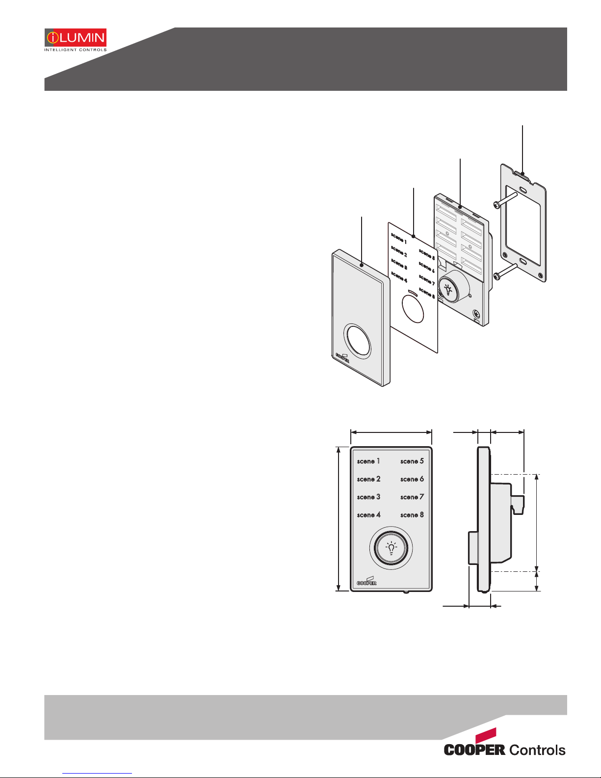
Revio wall station
2.75 in.
(70 mm)
4.84 in.
(123 mm)
0.65 in.
(17 mm)
3.26 in.
(83 mm)
1.41 in.
(36 mm)
1.37 in.
(35 mm)
0.43 in.
(11 mm)
Installation guide
Introduction
Welcome
The iLumin Revio wall station from Cooper Controls
artfully combines understated elegance with high functionality. Barely larger than a standard switchplate, this
sleek, backlit panel allows you to instantly call up preprogrammed lighting scenes. The rotary dial can be used
to adjust the intensity of a chosen scene. An optional
infra-red remote control allows similar functionality from
anywhere within the room via the detector built into the
front panel of the Revio wall station. All control signals
are transmitted to the source controller(s) using robust
iCANnet connections. A range of standard insert sheets
are available or custom versions can be created, as necessary.
Controls
Scene selection
• Press a scene button to select a scene (the button will
illuminate).
• Turn the rotary dial to raise or lower the scene level.
• Use the on/off button (in the center of the rotary dial)
to switch all lights off (the function of the button can
also be altered to affect only certain areas). When the
button is pressed again, the last selected scene will be
resumed.
Supplied parts
Insert sheet
Front cover
Dimensions
Rear chassis plate
Main body
Zone function
Where certain buttons are programmed to control zones:
• Press a zone button to select a zone (the button will
ash).
• Turn the rotary dial to raise or lower the zone level.
• Use the on/off button to switch the zone on and off.
• Press a scene button to override previous zone set
tings, unless ignore has been programmed for that
particular zone.
• The zone function will timeout after ten seconds.
-
Cleaner switch
On the underside of the front cover, there is a small concealed press switch. Press the switch to isolate the scene
selectors for ten seconds. This action also sends a ‘hello’
message to the network to assist with device identication - this does not interfere with the operation of the wall
station or the rest of the system.
The Revio wall station is intended to t into a single gang
wall box with a minimum internal depth of 2 in. (51 mm).
Page 2
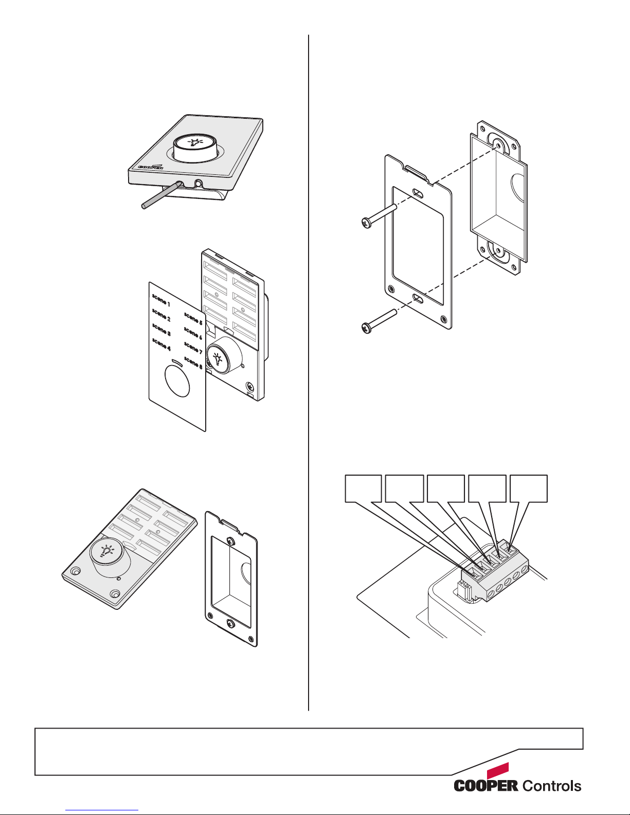
Disassembling the wall station
+12V
(red)
CAN-H
(white)
DRAIN
(gray)
0V
(black)
CAN-L
(blue)
1. On the underside of the front cover, beneath the rotary
dial, locate the small central recess. Carefully insert a
small implement (such as a pen or screwdriver) into
the recess and lever the front cover gently away from
the main body.
2. Unclip the front cover from the top of the main body.
3. With the front cover
removed, lift off the
insert sheet.
Fixing to a wallbox
The Revio wall station is intended to t into a single gang
wallbox with a minimum internal depth of 2 in. (51 mm).
With the Revio wall station disassembled, use the two
supplied long screws to secure the rear chassis plate to
the wallbox.
4. Remove the two retaining screws located just below
the rotary dial and lift the base of the main body away
from the rear chassis plate until it disengages.
5. Store all removed parts safe from damage.
Control wiring
The Revio wall station uses iCANnet connections to
ensure reliable and responsive transfer of control signals
between multiple devices.
Cable connections are made to a removable 5-way connector block located at the rear of the Revio wall station
main body:
Cable type: Belden™ 1502P or similar
Maximum cable length: 1000 ft. (305 m) *
Devices per segment: 100 (without bridge or repeater)
* A maximum segment distance of 1000m/3200ft is possible if an
additional 12V power supply is used.
Page 3
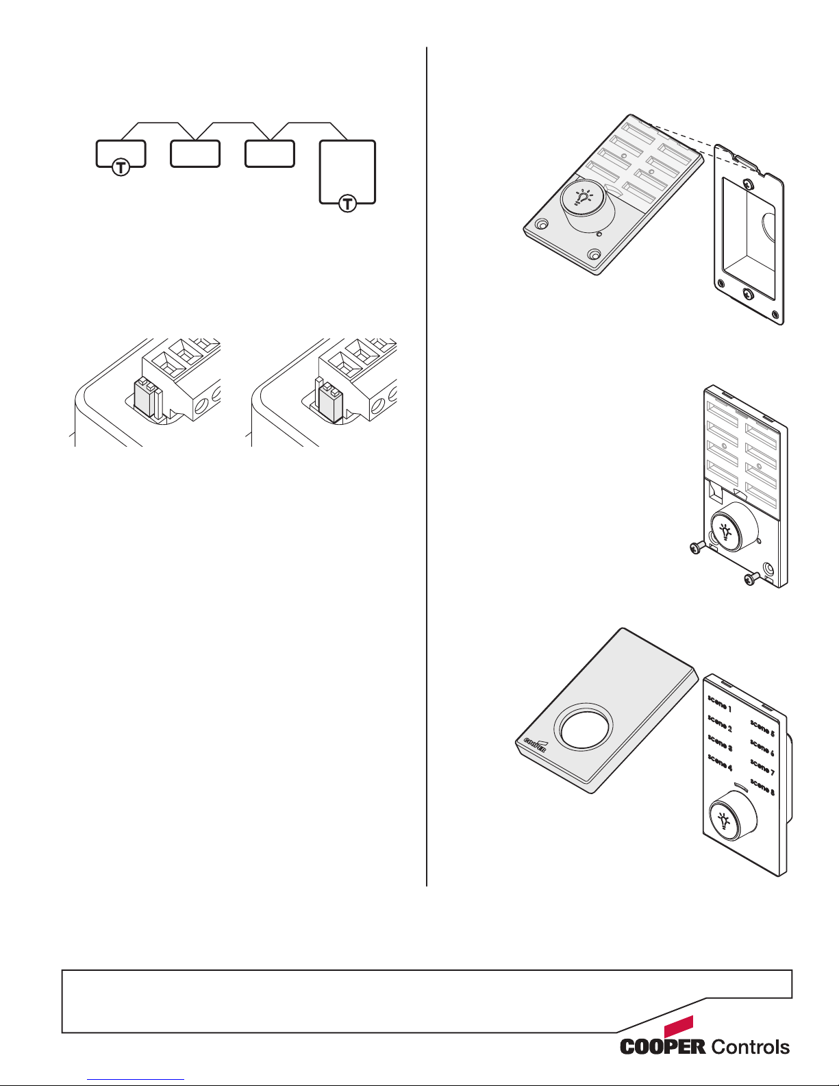
Universal
Source
Controller
DeviceDeviceDevice
Termination
The iCANnet link is a ‘daisy chain’ protocol that requires
termination on the devices located at either end of the
chain.
The Revio wall station is supplied with termination enabled as standard. If the Revio wall station is not connected as an end device in the chain, you need to disable
termination.
To disable termination, move the jumper from the upper
two pins to the lower two pins, as shown here:
Reassembling the wall station
1. Locate the upper slot on
the rear of the wall station
main body, place the
upper slot onto the
corresponding
‘lip’ of the rear
chassis plate.
2. Angle the lower part of the main body down so that it
ts closely against the rear chassis plate.
3. Insert and lightly tighten the
two retaining screws.
Termination on
Termination off
4. Place the insert sheet into position.
5. Attach the top edge of the front
cover to the main body.
6. Angle the front cover down and
press the lower part of it against the
main body until it clicks into place.
Page 4
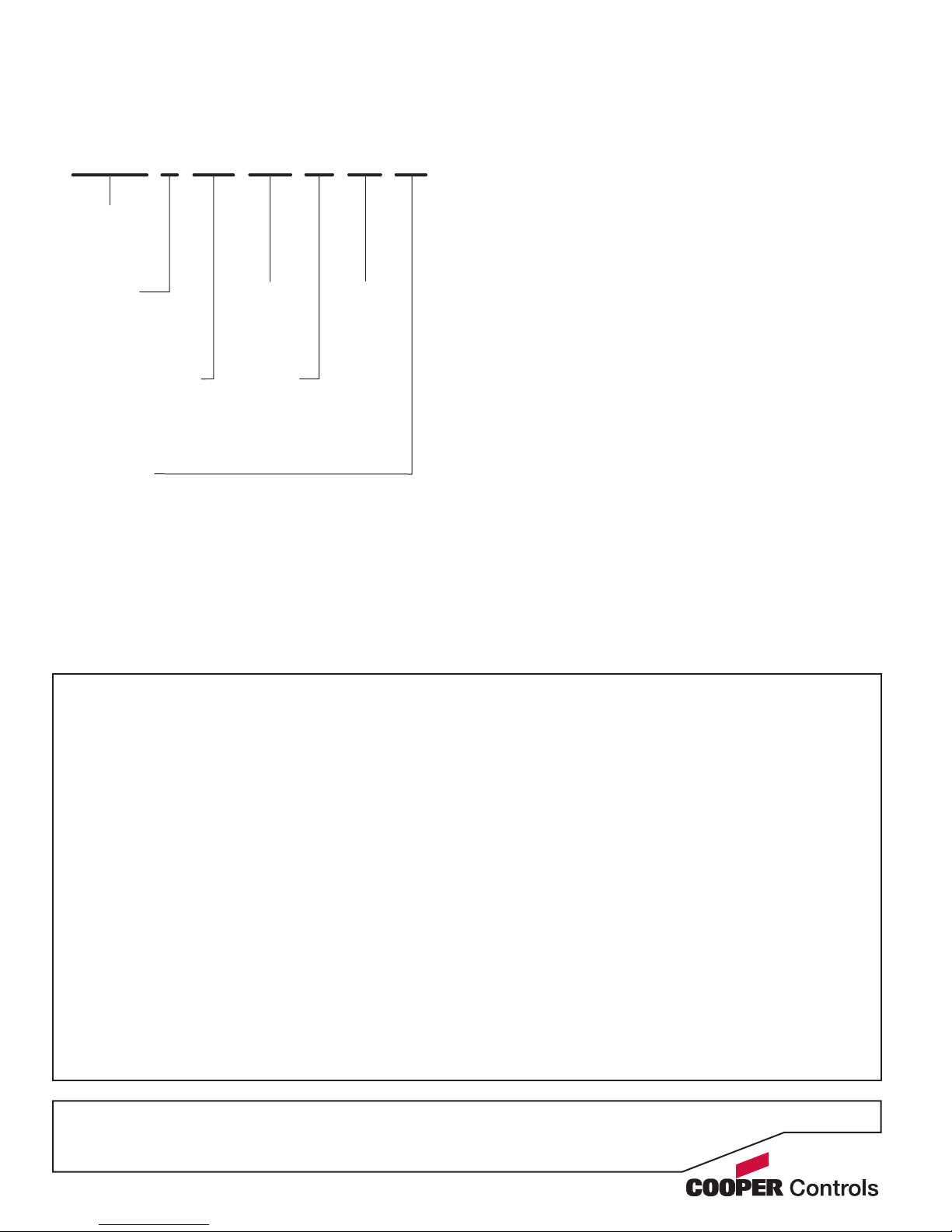
Model numbers
Each model is specied using a part number in the
following format:
CL V 4 4Z RL W IR T1
Cooper
iLumin
Revio
Ambient atmosphere requirements
Temperature 320F to 1040F (00C to +400C)
Humidity 0 to 95% non-condensing
Number
of buttons
in rst
column
Number of buttons
in second column.
Z denotes ‘Zone’
function
Insert text:
Blank Scene 1, Scene 2, etc.
T1 Preset 1, Preset 2, etc.
T2 General, Meeting, Seminar, Lecture
T3 Lunch, Cocktails, Dinner, Special
Raise/Lower
(always tted)
Insert color:
W - White
B - Black
G - Gray
V - Ivory
IR
Receiver
All products manufactured by Cooper Controls and
identied with the iLumin brand are warranted to be
free from defects in material and workmanship and shall
conform to and perform in accordance with Seller’s
written specications for a period of :
Five (5) years from date of shipment for all occupancy
sensors and Two (2) years from date of factory invoice
for our hardware and software on Lighting Control
Panels.
We warranty all our standard relays for a period of 10
years from date of factory invoice. We guarantee the
performance of our system to specications of your
money back.
This warranty will be limited to the repair or replace-
ment, at Seller’s discretion, of any such goods found
to be defective, upon their authorized return to Seller.
This limited warranty does not apply if the goods have
been damaged by accident, abuse, misuse, modication or misapplication, by damage during shipment or
by improper service.
There are no warranties, which extend beyond the hereinabove-limited warranty, INCLUDING, BUT NOT LIMITED TO, THE IMPLIED WARRANTY OF MERCHANTABILITY AND THE IMPLIED WARRANTY OF FITNESS.
No employee, agent, dealer, or other person is authorized to give any warranties on behalf of the Seller or to
assume for the Seller any other liability in connection
with any of its goods except in writing and signed by
the Seller. The Seller makes no representation that the
goods comply with any present or future federal, state
or local regulation or ordinance. Compliance is the Buyer’s responsibility.
The use of the Seller’s goods should be in accordance
with the provision of the National Electrical Code, UL
and/or other industry or military standards that are pertinent to the particular end use. Installation or use not in
accordance with these codes and standards could be
hazardous.
Document 73-888-00 IM8504 Iss.01
Cooper Controls
203 Cooper Circle, Peachtree, GA 30269
800-553-3879 www.coopercontrol.com
 Loading...