

Page 1
ILUMEN PID SOLUTION
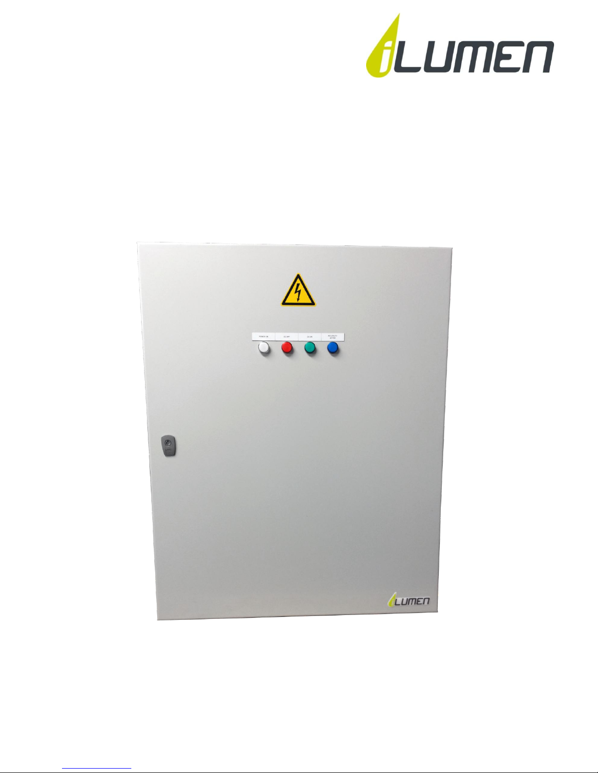
ILUMEN PIDBOX Utility
INSTALLATION MANUAL
Ilumen PIDbox utility – Version 1.0
Page 2

Ilumen
2
Installation Manual Ilumen PIDbox Utility v1.0
TABLE OF CONTENT
1 Information on this manual ................................................................................................................................. 4
1.1 Validity ................................................................................................................................................................ 4
1.2 Target group ..................................................................................................................................................... 4
1.3 Additional information ................................................................................................................................. 4
1.4 Symbols ............................................................................................................................................................... 4
2 Safety ............................................................................................................................................................................. 4
2.1 Appropriate usage .......................................................................................................................................... 4
2.2 Qualifications of skilled persons............................................................................................................... 5
2.3 Safety precautions .......................................................................................................................................... 5
2.3.1 Electric shock .......................................................................................................................................... 5
2.3.2 Electrostatic discharge ........................................................................................................................ 5
3 Scope of delivery ....................................................................................................................................................... 5
4 Product description ................................................................................................................................................. 5
5 Mounting ...................................................................................................................................................................... 6
5.1 Mounting location requirements ............................................................................................................. 6
5.2 Mounting the Ilumen PIDbox utility using the mounting holes .................................................. 6
6 Electrical connections ............................................................................................................................................. 7
6.1 Earth connection ............................................................................................................................................. 7
6.2 Solar array and inverter connections ..................................................................................................... 8
6.3 Connection Diagrams .................................................................................................................................... 9
6.3.1 One DC-circuit breaker (1xMPPT, 1xInverter) ......................................................................... 9
6.3.2 Two DC-circuit breakers (2xMPPT, 1xInverter) ...................................................................... 9
6.3.3 Two DC-circuit breakers (2xMPPT, 2xInverter) ...................................................................... 9
6.4 Schematics ...................................................................................................................................................... 10
7 Commissioning ....................................................................................................................................................... 11
7.1 Check ................................................................................................................................................................. 11
7.2 Starting up the Ilumen PID utility ......................................................................................................... 11
7.3 Manually activate DC-circuit breakers ................................................................................................ 12
8 Installation summary ........................................................................................................................................... 13
9 Decommissioning the Ilumen PIDbox utility ............................................................................................. 13
9.1 Disassembling the PIDbox utility .......................................................................................................... 13
9.2 Packing the PIDbox utility ........................................................................................................................ 13
Page 3

Ilumen
3
Installation Manual Ilumen PIDbox Utility v1.0
9.3 Disposing of the PIDbox utility............................................................................................................... 13
10 Troubleshooting ................................................................................................................................................ 14
10.1 Faults................................................................................................................................................................. 14
10.2 No good PID regeneration ........................................................................................................................ 14
10.3 Resetting the PIDbox utility .................................................................................................................... 14
10.4 Repairing the PIDbox utility .................................................................................................................... 15
11 Contact .................................................................................................................................................................. 15
12 Technical data .................................................................................................................................................... 16
Page 4

Ilumen
4
Installation Manual Ilumen PIDbox Utility v1.0
1 INFORMATION ON THIS MANUAL
This manual contains instructions on how to install the Ilumen PIDbox utility.
1.1 VALIDITY
This manual applies to the Ilumen PIDbox utility v1.0.
1.2 TARGET GROUP
This manual is intended for skilled persons. Only qualified persons with the appropriate skills
are allowed to perform the tasks set forth in this manual.
1.3 ADDITIONAL INFORMATION
Links to additional information can be found at www.ilumen.be
Ilumen PIDbox utility datasheet
What is PID?
PID checker
1.4 SYMBOLS
Symbol
Explanation
Indicates a hazardous situation which, if not avoided, will result in
property damage
Indicates a hazardous situation which, if not avoided, will result in death
or serious injury
Information that is important for a specific topic or objective, but is not
safety-relevant
2 SAFETY
2.1 APPROPRIATE USAGE
The Ilumen PIDbox utility applies a voltage to PV modules in reference to earth. The device may
only be switched on when the installation is executed as described in this manual.
Before installing the Ilumen PIDbox utility, ensure that the permitted operating range of each
component is maintained at all times.
Before using the Ilumen PIDbox utility you have to obtain the appropriate approval from the
manufacturer of the PV modules.
Any applications other than those described here shall be considered contrary to the
appropriate usage. Alternative use or modification of the Ilumen PIDbox utility will void
warranty claims and operation permit.
Page 5

Ilumen
5
Installation Manual Ilumen PIDbox Utility v1.0
2.2 QUALIFICATIONS OF SKILLED PERSONS
The work described in this document must be performed by skilled personnel only. Skilled
personnel must have the following qualifications:
Knowledge of how an inverter works and how it is operated
Training in how to deal with the dangers and risks involved in installing and operating
electrical devices and plants
Training in the installation and commissioning of electrical devices and plants
Knowledge of all applicable standards and directives
Knowledge and observance of this document and all safety precautions
2.3 SAFETY PRECAUTIONS
2.3.1 ELECTRIC SHOCK
When the Ilumen PIDbox utility is in operation, voltage will be present. Prior to
maintenance work on the PV plant switch off the Ilumen PIDbox utility.
When you want to change the arrangement of the Ilumen PIDbox utility you must switch
off the Ilumen PIDbox utility 20 minutes prior to making any changes.
2.3.2 ELECTROSTATIC DISCHARGE
Never operate the Ilumen PIDbox utility when not properly installed or when the
components are not closed properly. Always make sure the grounding of the Ilumen
PIDbox utility is done correctly.
3 SCOPE OF DELIVERY
1x Ilumen PIDbox utility
Containing the following components
a. iLumen PID controller
b. PLC
c. iLumen Energy meter
d. Timer
e. 1 or 2 automated DC-circuit breakers (according the ordering form)
f. Installation manual
4 PRODUCT DESCRIPTION
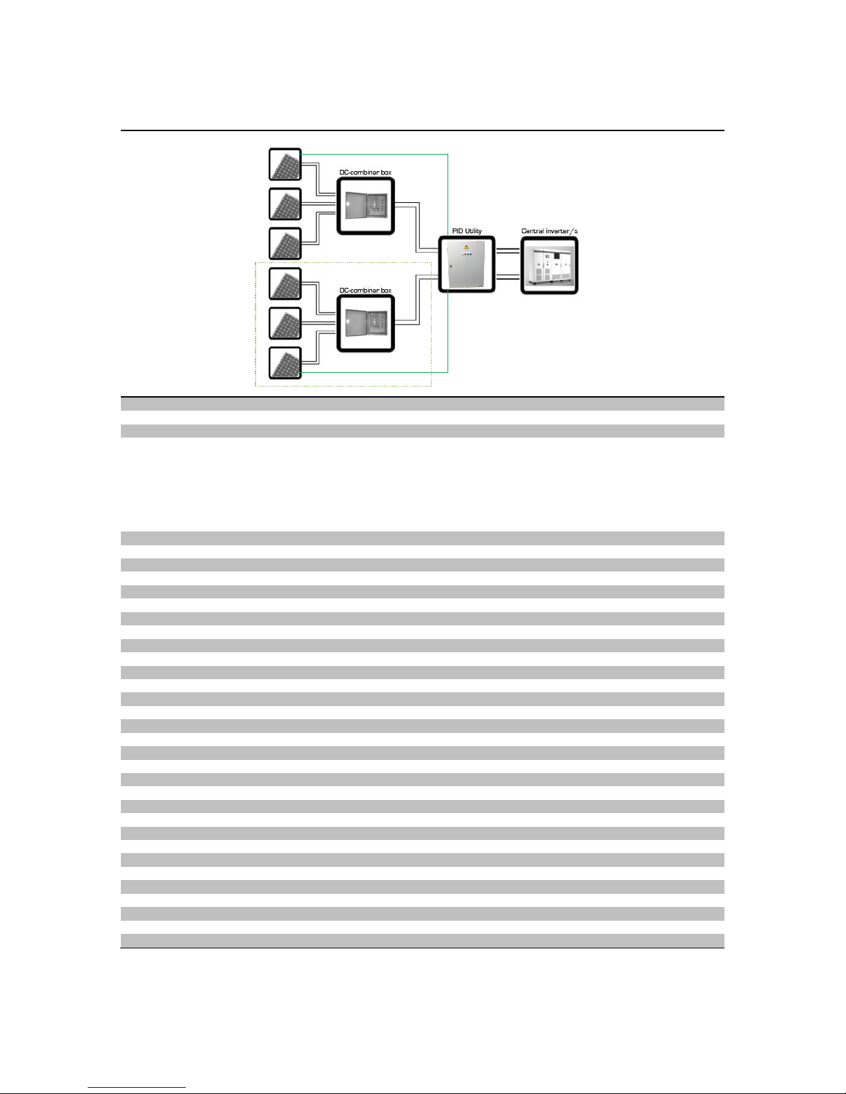
The Ilumen PIDbox utility is placed between the inverter and the solar array strings. The power
of the strings goes through the PIDbox utility, entering on one side “PV in” and leaving on the
other “Inv. out”. This means the Ilumen PIDbox utility is placed in series between the PV panels
and the inverter. You can use one Ilumen PIDbox utility per 1 or 2 MPP trackers (when ordered
with 1 or 2 DC-circuit breakers respectively).
Page 6
Ilumen
6
Installation Manual Ilumen PIDbox Utility v1.0
5 MOUNTING
5.1 MOUNTING LOCATION REQUIREMENTS
The installation site must be freely and safely accessible at all times without the
necessity for any auxiliary equipment.
The mounting location should be inside a well ventilated- and windproof location.
Do not place the Ilumen PIDbox utility in a dusty environment.
The ambient temperature must be between -10 and 35°C.
Normally the PIDbox utility is installed right next the inverter or close to the DC-
combiner box.
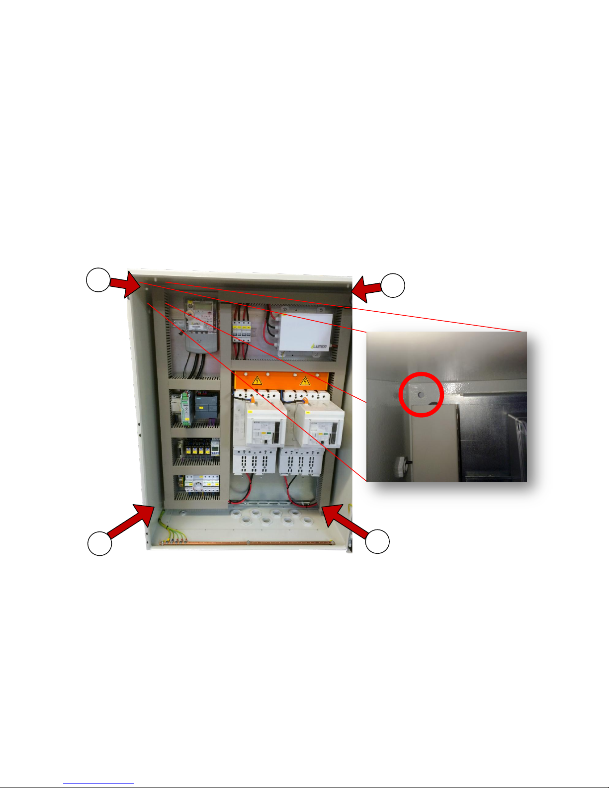
5.2 MOUNTING THE ILUMEN PIDBOX UTILITY USING THE MOUNTING HOLES
1. Mark the 4 positions of the drill holes on the mounting surface
2. Drill the holes
3. Insert the wall plugs (if necessary)
4. Screw the Ilumen PID Utility to the mounting surface and make sure adequate washers
are installed.
5. Check if mounted securely
1 2 3
4
Page 7
Ilumen
7
Installation Manual Ilumen PIDbox Utility v1.0
When lifting the PIDbox utility, always ask a second person to assist or use special
lifting equipment. One PIDbox utility weights around 90 kg. Be cautious for back
injuries!
6 ELECTRICAL CONNECTIONS
When installing the Ilumen PIDbox utility, the DC side of the PV plant must be switched off. After
the installation is done, you can switch the DC switch back on. Also switch on the circuit breaker
manually when needed inside the PIDbox utility.
A standard 1 phase AC connection (230V AC) must be available on installation. This outlet
should be on at all times.
6.1 EARTH CONNECTION
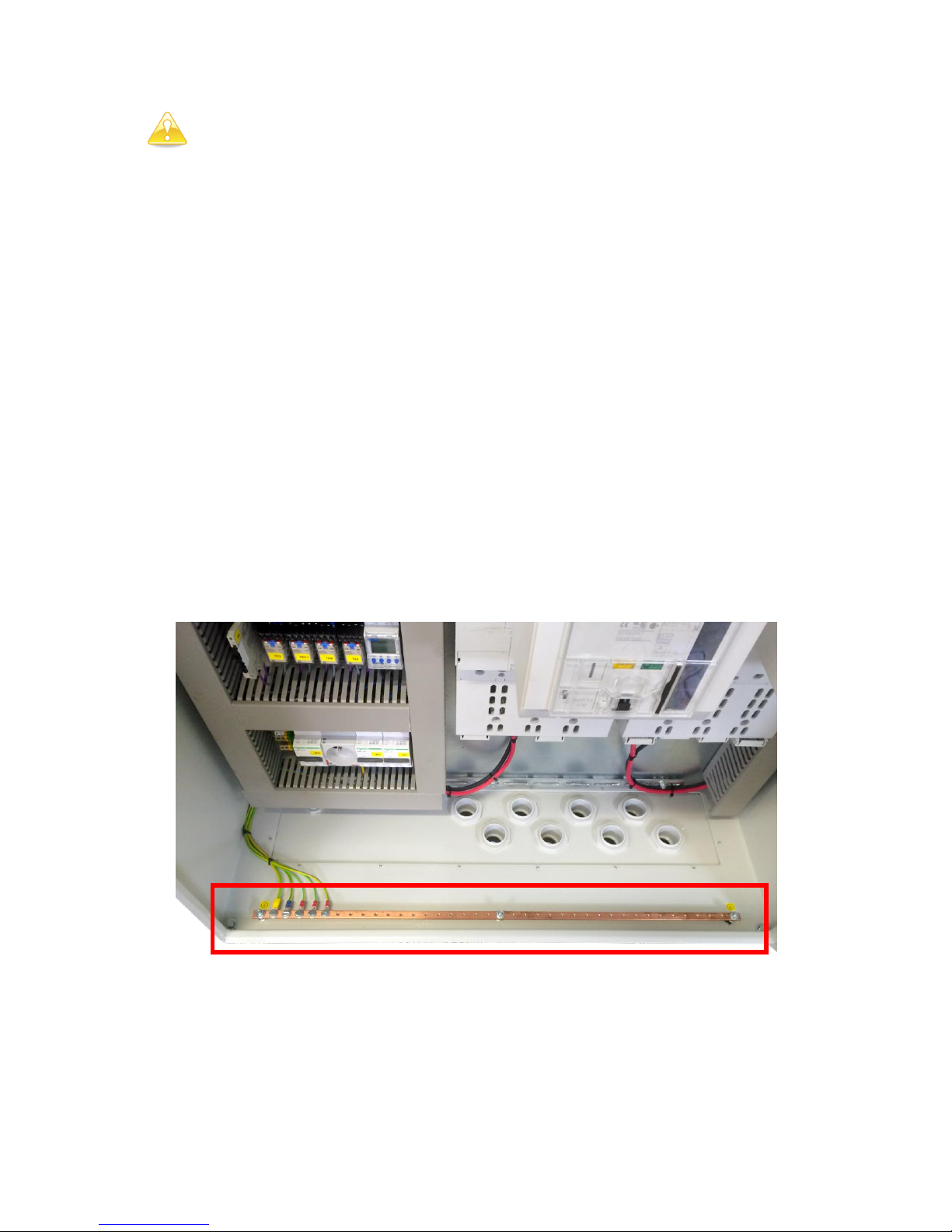
To achieve the best result, the frames of the solar modules must be connected to the earth
connector of the Ilumen PIDbox utility. For optimal result you must lay a cable (2.5-4mm2) to the
mounting structure of the solar modules (make sure mounting structures and frames of the solar
modules are electrically conducting). It is important that all frames of all solar modules are at
the earth potential, if necessary you have to interconnect the mounting structures with
additional cables.
Connect the earth cable to the earth bar inside the PIDbox utility
Page 8
Ilumen
8
Installation Manual Ilumen PIDbox Utility v1.0
6.2 SOLAR ARRAY AND INVERTER CONNECTIONS
When installing the PIDbox utility between the PV array and inverter always
switch off the DC switch of the inverter
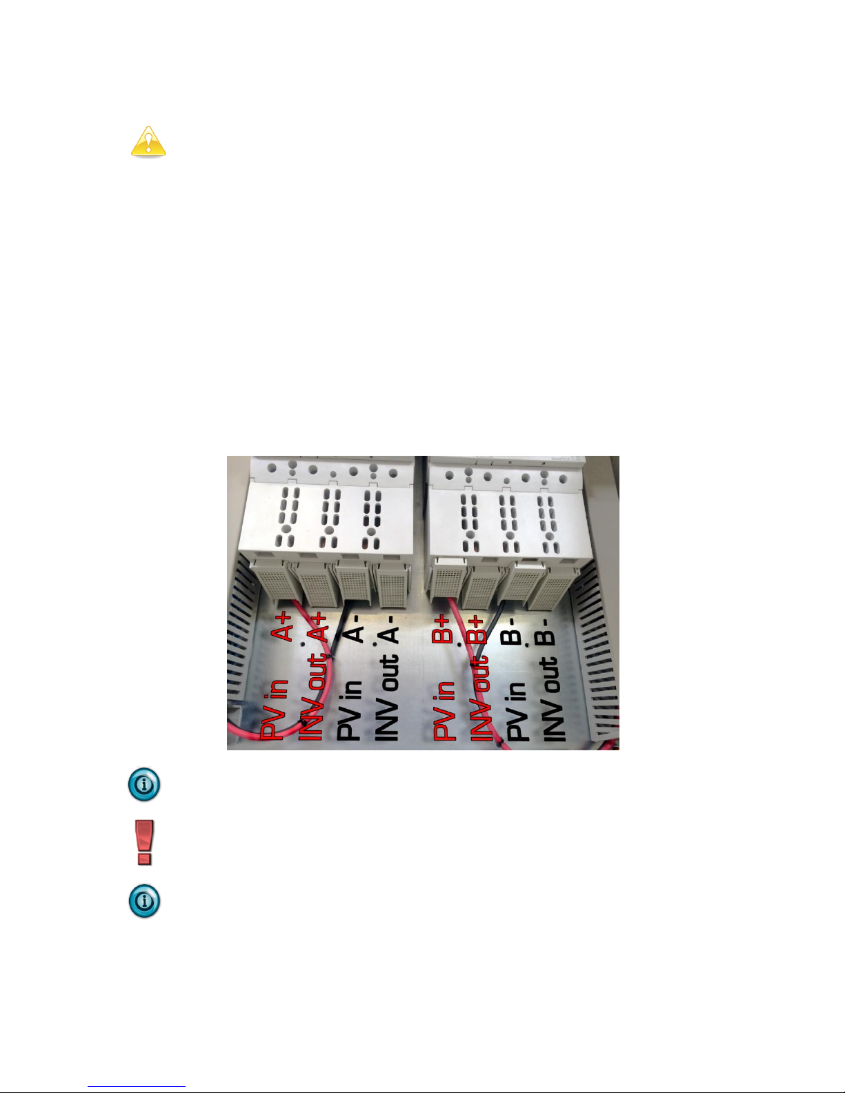
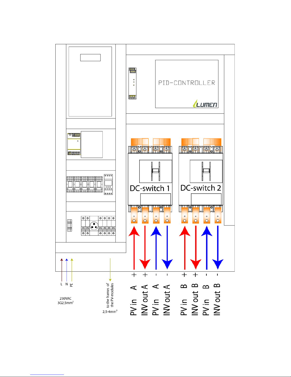
1. Connect the positive DC cable coming from the first PV array. Connect it to the “PV in A+”
position.
2. Connect the negative DC cable coming from the first PV array. Connect it to the “PV in A-”
position.
3. Connect the positive DC cable coming from the second PV array (optional). Connect it to
the “PV in B+” position.
4. Connect the negative DC cable coming from the second PV array (optional). Connect it to
the “PV in B-” position.
5. Connect the “INV out A+” position to the positive side of the inverter of the first PV array
6. Connect the “INV out A-” position to the negative side of the inverter of the first PV array
7. Connect the “INV out B+” (optional) position to the positive side of the inverter of the
second PV array
8. Connect the “INV out B-” (optional) position to the negative side of the inverter of the
second PV array
If you work with inverters with multiple MPPT’s you cannot mix the PV arrays
from multiple MPPT’s.
The maximum current that can pass through the Ilumen PIDbox utility per channel
/ MPPT is indicated on the DC circuit breaker and on the type plate on the side of
the PIDbox utility. Make sure this is never exceeded.
Make sure the PV arrays are connected to the “PV in A” and “PV in B” side of the
Ilumen PIDbox utility, NEVER to the “INV out A” or “INV out B” side.
Page 9
Ilumen
9
Installation Manual Ilumen PIDbox Utility v1.0
6.3 CONNECTION DIAGRAMS
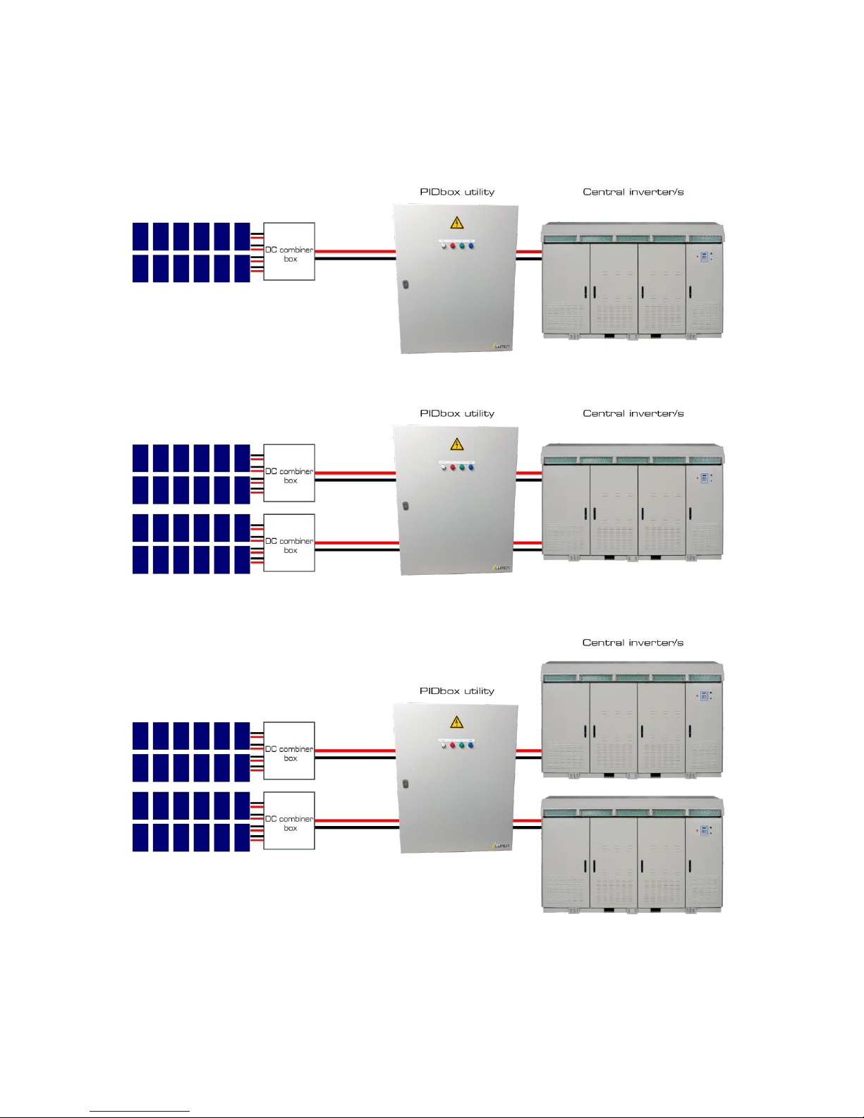
Several solutions are possible. Here you find the most common possible connections.
6.3.1 ONE DC-CIRCUIT BREAKER (1XMPPT, 1XINVERTER)
6.3.2 TWO DC-CIRCUIT BREAKERS (2XMPPT, 1XINVERTER)
6.3.3 TWO DC-CIRCUIT BREAKERS (2XMPPT, 2XINVERTER)
Page 10
Ilumen
10
Installation Manual Ilumen PIDbox Utility v1.0
6.4 SCHEMATICS
Page 11
Ilumen
11
Installation Manual Ilumen PIDbox Utility v1.0
7 COMMISSIONING
7.1 CHECK
Do a final check whether everything is properly mounted and connected (see chapter 5 and 6 for
details):
The PV frames are all connected to the same earth as the earth pin of the Ilumen PIDbox
utility
The PV and inverter DC cables are correctly connected
The AC connection is made properly
If all these points are installed correctly you can start up the Ilumen PIDbox utility.
7.2 STARTING UP THE ILUMEN PID UTILITY
The Ilumen PIDbox utility can only work in an automatic mode. To start up the Ilumen PIDbox
utility, switch on the AC circuit breaker. Next see if the light on the Ilumen PIDbox utility starts
burning. After checking the system it will be switched on automatically.
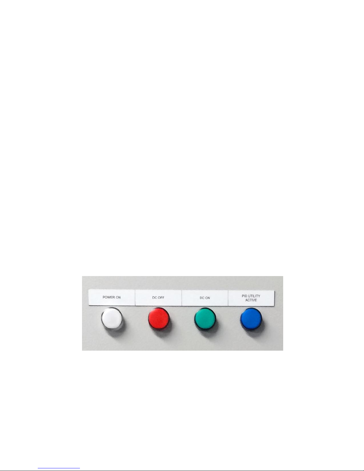
When the Ilumen PIDbox utility is hooked up correctly to the inverter you will see the following
status light readouts.
White: device is switched on
RED: DC circuit breakers are off. This light should burn during the night (starting from
22.30h)
GREEN:. DC circuit breakers are on. This light should burn during the day (starting
from 04.30h)
BLUE: PID controller is switched on and cures the PV system. It takes a minute or so
that the blue light will come on after the red light starts to light up.
So there are 2 scenarios:
Daytime: white light and green light on
Nighttime: white light, red light and blue light on
Page 12
Ilumen
12
Installation Manual Ilumen PIDbox Utility v1.0
7.3 MANUALLY ACTIVATE DC-CIRCUIT BREAKERS
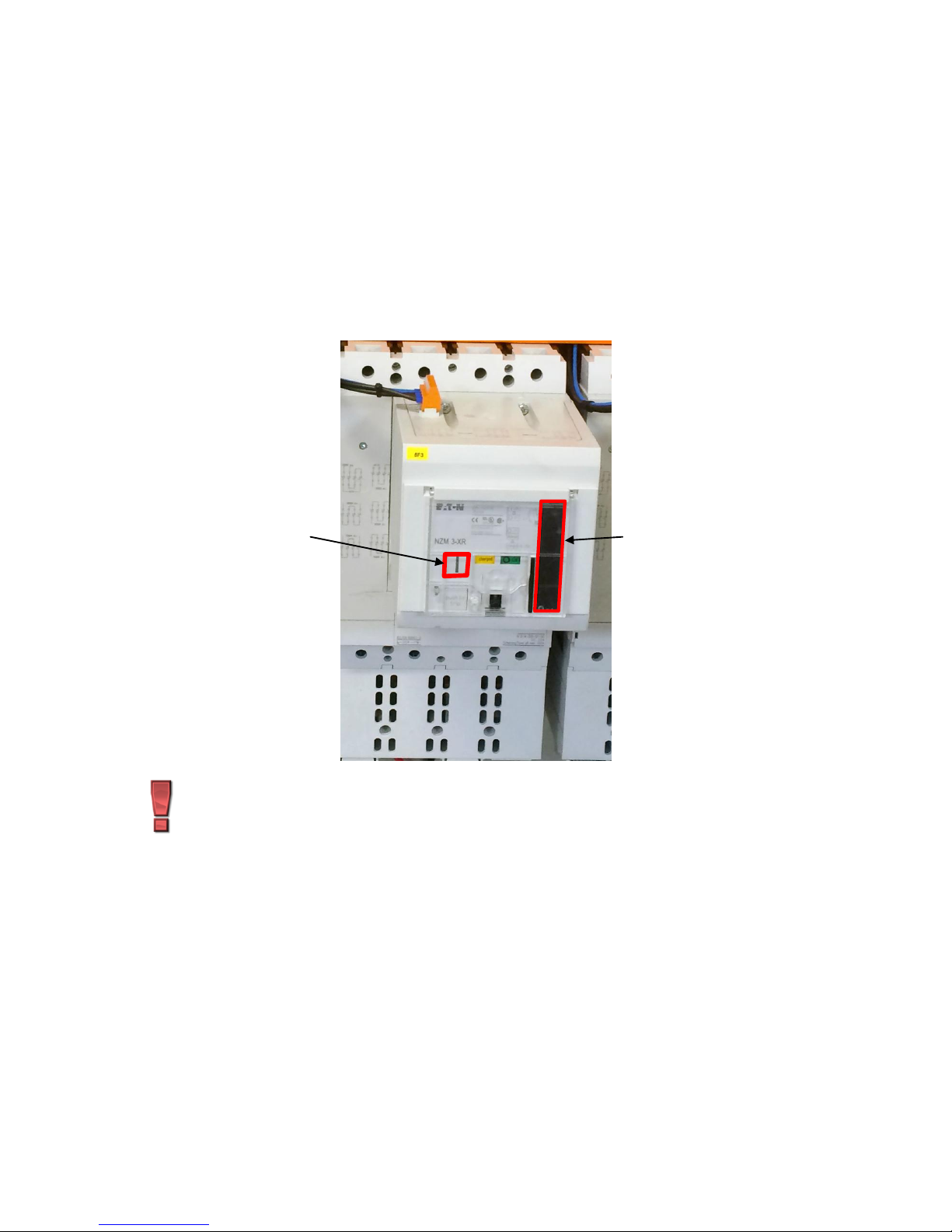
When it is necessary to manually activate the DC circuit breakers you can follow this guide
below. You can manually activate it e.g. when the AC-power is not connected but you still want
to use the PV-panels for your inverter.
You can manually activate the DC circuit breakers by opening up the plastic see-trough cover
and pressing the “I” button. If this doesn’t work you will have to charge up the circuit breaker.
Pull the lever on the right side of the circuit breaker all the way down. Let go and repeat this
until the words “charged” appear in the window. Press the “I” button again. This should only be
done after all DC-connections are made.
Make sure all connections are made properly before activating the DC-circuit
breaker manually.
lever
‘I’-button
Page 13

Ilumen
13
Installation Manual Ilumen PIDbox Utility v1.0
8 INSTALLATION SUMMARY
1) Take the necessary safety precautions (DC switch of the inverter off).
2) Mount the Ilumen PIDbox utility correctly to a wall using the mounting holes.
3) Connect the Ilumen PIDbox utility earth bar to the frames of the PV modules and check
the interconnections between the PV casings.
4) Disconnect the PV array cables from the inverter.
5) Mind the maximum allowed current through the DC circuit breakers of the PIDbox utility
6) Connect the PV array cables to the Ilumen PIDbox utility inputs (see 6.2 for details).
7) Connect the Ilumen PIDbox utility to the inverter (see 6.2 for details).
8) Connect the AC power
9) Switch on the AC circuit breaker
10) Turn the DC switch on inside the inverter or the DC combiner box
9 DECOMMISSIONING THE ILUMEN PIDBOX UTILITY
9.1 DISASSEMBLING THE PIDBOX UTILITY
Switch off the Ilumen PIDbox utility by switching off the main AC circuit breaker. Switch off the
DC power to the PIDbox utility inside the inverter or the DC combiner box. Disconnect the
Ilumen PIDbox utility from the AC grid. Wait a minimum of 20 minutes. Disconnect the DC cables
from the PIDbox utility. Disconnect all earth connections.
When all electrical connections are disconnected you can dismount the Ilumen PIDbox utility.
When doing any kind of work on the PIDbox utility, always switch off the
DC power to the device inside the inverter or the DC combiner boxes.
9.2 PACKING THE PIDBOX UTILITY
To pack the PIDbox utility use the original packaging or packaging suitable for the weight and
dimensions of the PIDbox utility (see Section 12 "Technical Data").
9.3 DISPOSING OF THE PIDBOX UTILITY
Dispose of the PIDbox utility at the end of its service life in accordance with the disposal
regulations for electronic waste currently applicable at the installation site.
Page 14

Ilumen
14
Installation Manual Ilumen PIDbox Utility v1.0
10 TROUBLESHOOTING
10.1 FAULTS
Lights readout
Fault
Corrective action
No lights visible
Product does not work
Make sure the AC-power is connected
and AC voltage is present. Also make
sure that all the AC circuit breakers
inside the PIDbox utility are switched
on.
No lights visible
Product does work. The
front panel lights can be
defective
Please contact iLumen technical service.
Blue light does not
burn during the night
while the red and
white lights are
burning.
Product does not cure the
panels
This can have 2 reasons:
It takes about 1 minute to
activate the blue light after the
red light has turned on.
Earth connection between
PIDbox utility and the frame of
the modules is interrupted.
Alternating lights red
and green.
The PIDbox is not in
automatic mode. The
position of the DC-circuit
breaker doesn’t correspond
with the position it should
be in.
Check that the DC circuit breakers are in
automatic mode. Please check that the
plastic see-trough covers of the DC
circuit breakers are closed properly. A
black latch should click over the cover.
Red light during the
day when in automatic
mode.
The power to the inverter
is interrupted during the
day
The DC switch has tripped. Reset the
DC-switch.
If the problem persists, please contact
iLumen technical service.
10.2 NO GOOD PID REGENERATION
If the modules are not regenerating or not regenerating fast enough you should check following
things:
Check the grounding of the system. If necessary you should place additional
interconnections between the frames of the modules.
Is the Ilumen PIDbox utility properly connected to the grid?
Is the AC power properly connected (is its indication light burning)?
Let an expert check if the problem you’re having with the yield is caused by PID
10.3 RESETTING THE PIDBOX UTILITY
The PIDbox utility can simply be reset by switching off the AC-power. Wait 20 seconds and
switch the AC-power back on.
If resetting does not help fixing your problem, please consult chapter 10.1 of this manual.
Page 15

Ilumen
15
Installation Manual Ilumen PIDbox Utility v1.0
10.4 REPAIRING THE PIDBOX UTILITY
Do not try to repair the PIDbox utility by yourself without contacting iLumen. The warranty will
be void.
Always contact iLumen technical service if your PIDbox utility is broken.
11 CONTACT
Ilumen bvba
Ambachtsstraat 19
3980 Tessenderlo
Belgium
Tel: +32 13 30 61 77
Page 16
Ilumen
16
Installation Manual Ilumen PIDbox Utility v1.0
12 TECHNICAL DATA
Switch example
PV array / inverter input
Input PV voltage range
80 - 1000 V
Output voltage to ground
Up to 1250 V
Maximum PV current / input
V160
V200
V320
V400
V500
V800
160 A
200 A
320 A
400 A
500 A
800 A
Number of independent DC inputs
1 or 2 (specify when ordering)
Maximum output current in operation
20 mA
GRID (AC)
Nominal AC voltage
110 to 130 V or 220 to 250 V
Nominal AC grid frequency
50 to 60 Hz
Power consumption in standby operation
< 10 W
Typical power consumption in operation
50 W
Maximum power consumption
80 W
General data
Dimensions IP44 (W x D x H)
800 x 400 x 1000 mm
Dimensions IP65 (W x D x H)
1000x400x1000 mm
Dimensions IP44 (W x D x H) model V800
1250 x 420 x 1250 mm
Dimensions IP65 (W x D x H) model V800
1200x400x1000 mm
Weight
95 kg
Operating temperature range
-25 to 60 °C (-13 to 140 °F)
Environmental conditions
IP44 – indoor use only
IP65 – outdoor use (specify when ordering)
Configuration
Maximum one MPPT per DC-input
None of the connected solar module poles may become grounded
Communication
Optional
GPRS
Various
Warranty
Up to 20 years
Certificates
www.ilumen.be
Registration before use
www.myilumen.be
optional
Page 17

Ilumen
17
Installation Manual Ilumen PIDbox Utility v1.0
 Loading...