

Page 1
ILS Presentation Systems
Better for presenters, better for the audience
Installing the new ILS pedestal.
The ILS pedestal places ILS22, ILS21, ILS15 or other VESA mountable displays on an electrically
height-adjustable foot. There are 5 parts in the pedestal that are need to be put together with the cables
that are selected by the customer for support of the specific lectern display.
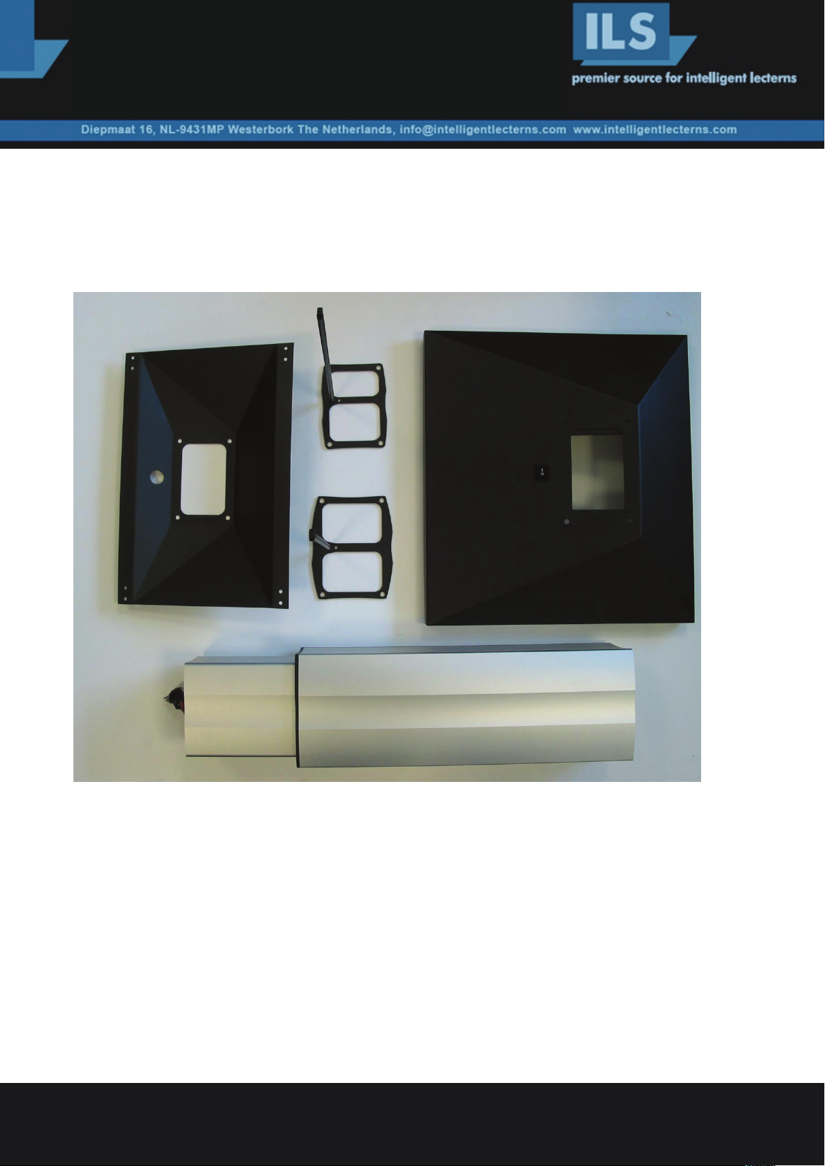
Figure 1. The pedestal components for the ILS22GL
Clockwise: The top support plate, 2 cable guides, 1 floor module, 1 Powerlift pillar.
The 2 cable guides have a long steel rod on a frame with the exact appearance of the top and the bottom part of
the pillar, these will go with the pin sticking inside on the top between pillar and top support plate and the bottom
one will go with its pin past the motor in the bottom and fits between the bottom of the pillar and the floor plate.
M8 screws hold the system together.
Intelligent Lectern Systems BV Amsterdam / Westerbork / Mumbai / San Diego
write to enquiry@intelligentlecterns.com , call +31 20 2400232 (Henk de Groot)
Product specifications are subject to change. 081001EN
Page 2
To accommodate for the wide range of height adjustment, the cables are managed in an S-curve that is almost
straight when the pillar is at top height, allowing for at least 30 cm of cable margin on the top to plug into the
ILS22 I/O bay. See figure 2. The picture is for clarity, now first put all needed cables from the bottom end through
the pillar so that they appear at the top
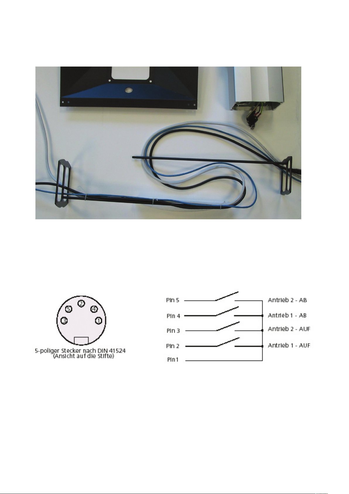
Figure 2.
Now tie the cables together on the top rod of the cable managers, include a tie wrap through the eye, and insert
this into the top of the pillar (while still in its low position). You may loosely put screws in to hold this in place.
Once completed, temporarily apply power to the pillar. Short on the DIN socket (see figure 3) the pins 1 and 2 to
make the pillar come out all the way, this will tell you how long the cables must be inside.
Then shorten 1 and 4, to make the pillar go to its lowest point.
Now that you know the length of the cables, tie the cables to the bottom cable manager and insert this inside the
pillar. Now you can mount the pillar on the foot. And fasten the bolts tightly.
2
Page 3

Put the pedestal on its foot and mount the top support pillar. You now have all the cables come out to fit the
ILS22GL top. Put a box or a few books under one side of the foot such that the top plane of the support plate
is horizontal, this will make it easier to mount the top with the 8 M4 screws. First attach the audience side very
loosely. Then connect all the cables, then fixate all screws.
If you have included the option for one or two side tables, you must include both weights in the foot.
The side tablets can be mounted either in a wide (top sample in the picture) or in a portrait format. And closer to
the center or more removed from it. For the ILS22 it will be further out. Choose the appropriate screw holes and
make sure the bars and tablets are properly chosen to keep a level tablet when the pillar is at a 12° angle.
Once the tablets are fixed the tablet center piece fits on top of the top cable guide and under the top support
plate of the ILS22.
Via the hole in the top plate a mouse is connected internally in the ILS22 I/O bay and can be used either on the
left or on the right side. The A4 size tablets may support larger tablets or a single U-shape tablet that goes around
the ILS22 head on the presenter side.
Mounting other ILS lecterns and displays.
The ILS21R is mounted directly on the pillar’s top cable guide without a support plate, however the tablets will fit
in the wider configuration. The ILS12 has a special tilt/VESA mount head that can sit on top of the upper cable
guide, with the tablet option in between.
Open the top VESA cover and mount the 4 positions needed for the display, manage the connecting cables
through the opening on the presenter side after including the display power supply in this head.
Choose the appropriate tilt level, the angles once installed on the foot are 12°, 18° or 24° (this includes the
angle of 12° of the pillar on the floor plate!) Then tighten the screws in that locked position.
3
 Loading...