

Page 1
Installation Manual
ILS24H
types ILS24N17CLA; ILS24N17FLD; ILS24N17OBX ; ILS24C22L2T
revision date: Sep 15, 2012, version 0.9
Page 2
1. Introduction.
Dear systems installer,
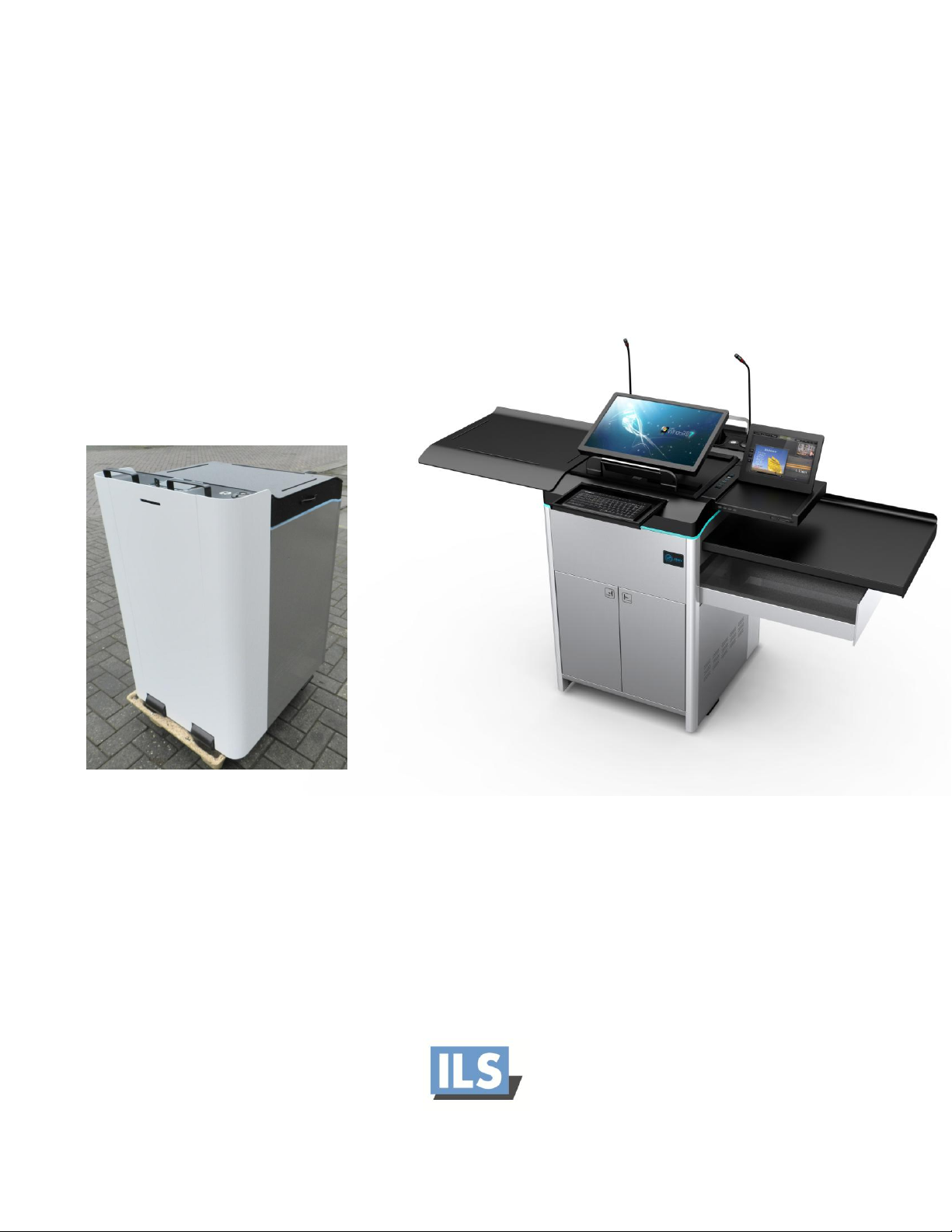
You have received our ILS24 lectern system in a carton box or wooden crate on pallet.
1. Lift the carton box carefully and slowly up to reveal the ILS24.
a. If the system arrives in a crate, open the top slightly and unscrew the pallet in the
bottom, then lift all sides up to remove the entire crate, the system is now again on its
pallet.
2. Unwrap the padding. Bring the lectern to its final destination.
3. Before removing the pallet, please make sure that there is no cable hanging from the bottom
hole of the lectern, with the risk that such cables could be damaged when taking the pallet away.
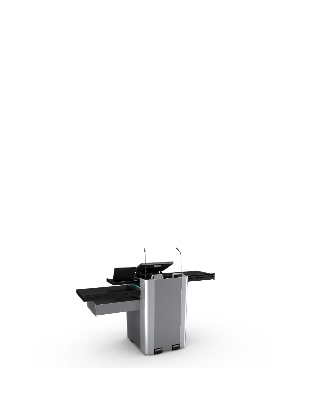
4. Now that the lectern is on the floor, you can use the Easymover by inserting it under the
presenter side of the lectern such that the 2 upward pins are catching in the holes of the toe
space. (See installation instructions Easymover ILS05A) <picture 2>
5. Without easy mover the lectern cabinet can be lifted by rotating it forward with the top handles
such that it rests on the rollers. (This is a heavy product and at least 2 strong persons should do
this!)
The lectern is now in its final destination.
Page 3
2. How to access the lectern, system familiarization.
Notice that the audience side, and its flat panel in the middle for access to the inside to bring power to
the lectern.
Page 4
1. There is a lock and key on the top center, which blocks the panel from being lifted out. Make
sure it is parallel to the front panel so that it is in the unlock position.
2. This panel can be lifted upwards about 7-8 cm and then pull forward. (this may take some force.
By adjusting the corners, this can be made easier, see later in this manual)
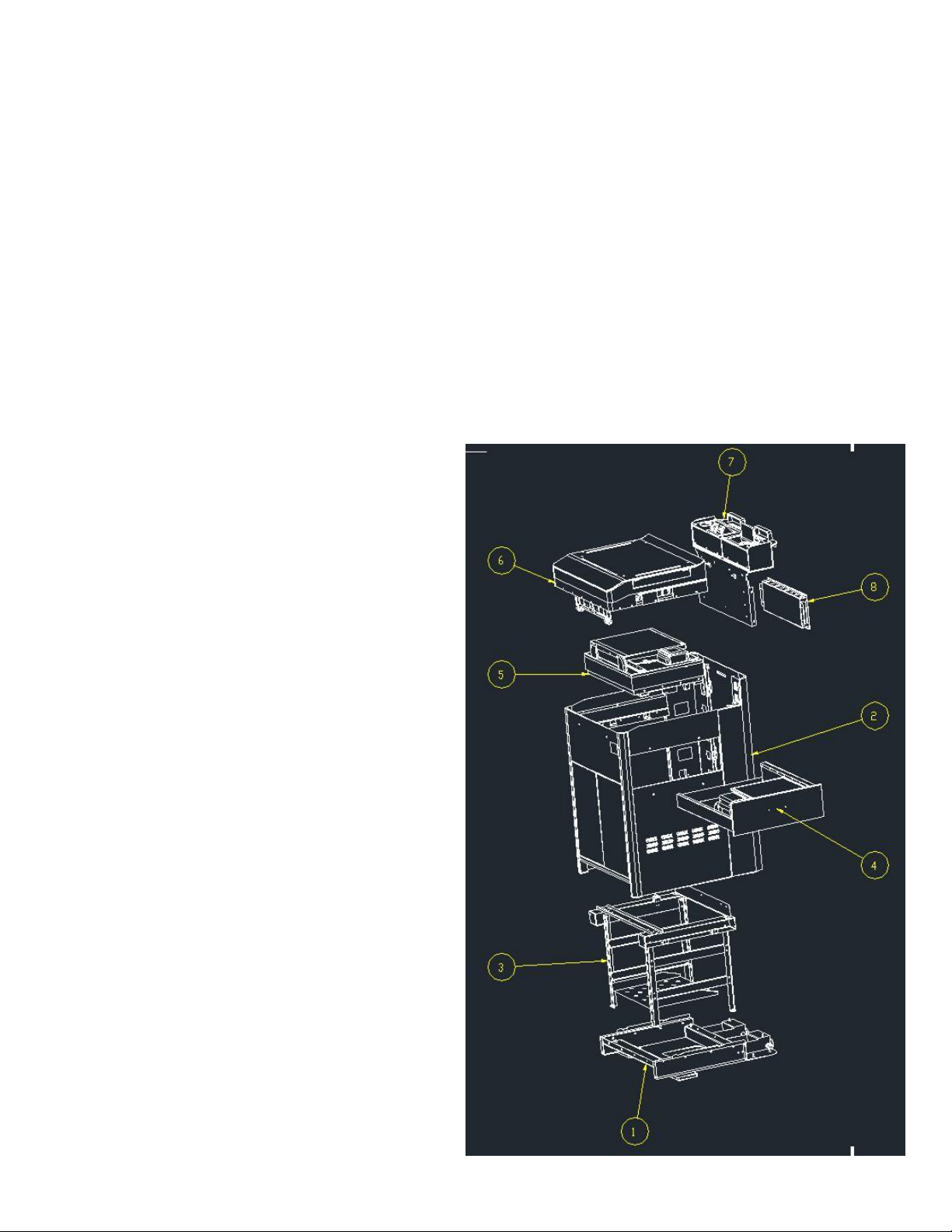
3. After opening, you can see the inside: the back of the 19”rack, a black box that houses the ILS
electronics, relays, patch board and 12V + 24V power supplies. The box has a cover for service
access. (item with arrow 8 in below drawing)
4. Notice there are 2 power extension cables, one is tucked in the top and serves as power for the
top power socket; the other is general system power. The IEC plug is intended to plug into the
permanent power outlet of e.g. a SURGEX power service system. For now, use a regular cable to
connect and power up the system.
5. The top cover can be opened now. It is able to open without power initially as ILS has taped the
locks of the top cover in the downward position, this allows opening the system without power.
After full access has been arrange and
tested with the RFID card for secure
access, the tape can be removed.
6. The top cover only opens and closes
with the RFID card; rack doors, the 12”
side panel [if present] and the drawer
are operated from the presenter side of
the lectern using the top UNLOCK
button after power has been given to
the lectern.
7. Notice that the cable guides have not
been installed, to allow access to the
back of the rack, in which you may opt
to install for example an EXTRON patch
panel first. Rack-nuts are already in
place for this in the middle of the rack.
The cable guides and screws are found
inside the large side drawer.
8. Modularity of the lectern assembly
allows us to accommodate specific
customer demands, we delivered 3
versions where the monitor base (arrow
5), the lift and the drawer (arrow 4) had
variation in components.
9. Now open the drawer and the 19” rack
access doors: After opening the top
cover and applying power, notice on the
right a strip of buttons that now have a
blue light under the buttons.
Page 5

10. Press the top
button (Unlock) You will
hear a click noise and in the
next 10 seconds you can
open the drawer . You can
open the rack doors by
pushing them inward, after
which they jump open.
You can open the drawer
and shift the optional 12”
panel to the right in the
same time. After about 10
seconds the locks go into
close positions.
11. You will see 2 rack shelves installed, the upper one intended for the PC, the lower smaller one
for the Panasonic player. Below that you find rack nuts, feel free to insert those in desired
positions, the nuts are intended to support 3 Rack-unit devices, such as matrix switchers,
control systems and e.g. a power conditioner and power switch.
12. After opening the top cover, you have found a support plateau for mostly the WACOM 2200 HD
pen-interactive monitor, it has the electrical lift controlled by the up/down buttons on the 6
button touch strip and manually allows for angular adjustment of the monitor. This is very quick
process by grabbing the monitor on the audience side and pull it to the desired angle, to lower
the angle, first pull it all the way up then down, then adjust to the desired height.
13. [Configurations at PNU only]:
a. ILS24N17FLD-type (studio version): VESA mount 75x75 and 100x100 off center to the
left to install the Sympodium ID370, with flush next to it, brackets that allow fixing
inside/between these an AMX NXD435
b. ILS24N17CLA-type (lecture hall version): Center VESA mount 75x75 + 100x100 for
attaching the ID370, whilst opening the drawer, reveals a tilt and lift mechanism for
installing an AMX 1200VG by using its VESA mount 75x75 back panel.
c. ILS24N17OBX-type (classroom version): Center VESA mount 100x100 on tilt plane for a
regular 17 inch monitor such as the DELL170P or 170S.
14. The electrical lift option for the main interactive monitor, for pen-interactivity and the larger
monitors, the electrical lift is a requirement. Note: the up/down buttons will only operate if the
sensors in the top register that the top cover has been moved all the way out to the left and
the 12” touch panel side table all the way to the right. If there is a potential that the monitor
could hit either of these, the sensors will prevent the lift from operating. If the lift does not
operate first verify if the top cover and the side panel are not blocking this function.
Page 6

15. ILS supplied special small Allen keys (hex shape with a hole in the middle), these keys are meant
for system service personnel, and these keys allow the opening of the side panels and the panel
above the 19” rack doors for accessing all sides of the system. If any panel were damaged, this
feature allows easy removal for repair of an individual component. If items – such as a pen –
were dropped in the top and do not
appear to have fallen into the drawer,
they may reside on the bottom of the lift
chamber. It is accessed by removing the
panel above the lift doors while the lift is
up.
16. Opening side panels with the hex-key:
When you need to open the side panels
and you take out the special screws, do
not force the panels open. Only let the
top come out a few millimeter to allow the panel to be pulled straight upwards! Then lift it up
out of its hinges. This prevents the internal holders to break away!
17. On the top audience side you will find a Sennheiser [or similar] shock-mount with a fitted XLR
cable, this cable attaches to the ILS service box in which a mute circuit has been integrated, and
a cable is hanging from this box downward. Connect here to an amplifier or an audio patch box.
If you prefer using your own mute circuitry, then go directly from the amplifier or patch box to
the shock-mount. Find the ILS mute switch on
the touch button panel.
18. Next to the microphone socket is another XLR
socket fixed in the surface, it is intended for a
reading light, power is between pin 2 and 3 as
for Littlite. Find the light switch on the touch
button panel.
In the center is the cable nook. Top section
(arrow 7 in previous drawing) is provided with
the AVA cable nook and BS power. (Some
configurations include both a cable nook and a
flip top connection box.
19. We have chosen to offer VGA connection cable for a notebook, PC audio connection cable, LAN
connection cable, 2 USB connection cables that have USB type B plugs on the tail. Other cable
patterns on request or inserted by the system integrator or your company. The power socket in
the cable nook or flip-top is a choice of Universal socket, British Standard socket or Euro DIN
socket. By providing female USB plugs on top, you have the option to insert any USB type cable
in the top. For connecting to the PC internally, the Sympodium and WACOM are providing 2
USB sockets. If both connection panel and cable nook are available then the nook would have a
type A male cable for USB, the female socket is then on the connection panel.
20. Find the up and down control buttons on the touch button panel on the right. (Mind the
lowering of the lift!! So that no garment or fingers are caught between rim and lift plate!) For
protection, the lift plate has a cover around the space under it, to prevent sharp edges when
Page 7

coming down and cutting into any obstacles. When all the way down the flaps can make some
noise, which may be considered normal – a necessary trade-off for avoiding risks of injury!
There is an important principle to allow the lift to work: The top cover must be fully open. In
order to protect the monitor from hitting the top cover, there is a magnet inside the top that
needs to be over the sensor in side rim to detect the cover being fully open and the lift allowed
to work! Similarly there is a sensor detecting full closure of the system upon which the fan and
the circuit for the SURGEX are disengaged.
21. The height adjustment covers a wide range of 37 cm! This allows the monitor to remain under
the surface of the lectern or rise tall above the lectern. The range is provided to always bring the
monitor level to elbow height for comfortable writing on a pen-interactive monitor. (Touch or
regular viewing monitors lay lower in the system, hence the Type –OBX has a tilt plane that lifts
upwards to an angle as needed for comfortable viewing and a steeper slope when using a touch
monitor.) Some recent versions have cut down on the height adjustment, to allow removal of
the protective flaps. This prevents metal on metal noise when a fixed microphone is near.
For the type –OBX, these buttons are not active and its 24 volt power supply is disconnected. You
may still use this feature (Jumper 9 in our connections box) for lowering screens, projectors or
curtains under this control button! See ILS24 electronics diagrams.
22. There is a keyboard hidden in the top rim (if it came with the system), lift and fold out to find
the keyboard. Its USB cable may be dangling down (careful when unpacking) and is to be
attached to the internal PC. [CLA version: When the document camera is not in use, a mouse
platform can be inserted above it, right next to the control button strip]. [Other versions: Users
may opt to insert a mouse platform next to the monitor in the spaces provided for it. The
aluminum plate for this is found in the drawer. The side drawer moves out far enough to still be
able to operate a document camera placed inside the drawer.]
23. Closing the 19” rack doors is best done by pressing the doors inwards lightly, roughly at the mid
height point. (Use the unlock button to open again.) <picture>
Page 8

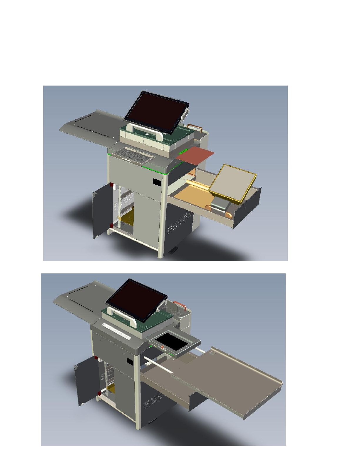
24. Large drawer: A very large side drawer was added to the system, it takes all of the internal
space available such that the drawer is almost leaning outwards a little bit. This large drawer
was accomplished in order to house both a large Wolfvision 9plus and an AMX1200VG series
right together inside this drawer. (for the –CLA types for lecture halls) The CLA types have the
secondary lift and tilt mechanism installed inside the drawer with a 75x75 VESA mountable
plate. Being the tallest of the Wolfvision document camera family, this camera will fit to the
millimeter. It is best to remove the rotating plane under the device as it has no meaning inside
the drawer. <picture>
25. The system has several feet on which it stands: front rollers come into action when the system is
tilted forward using the Easymover. Otherwise it will stand on 2 feet that are screwed in and out
as well as for assuring the system is level. 2 flat feet that are housed under the lectern body.
These feet are pushed inside and should be moved out a few centimeters for added stability.
3. Recommended wiring for installing SMART Sympodium ID370 or WACOM equivalents
1. The wiring of the Smart Sympodium can be accomplished in several ways. Since all annotations
also from peripheral devices need to go through the PC to be able to manipulate the data with
the pen-interactive monitor, normally the output is provided from the other graphics port of the
PC, so as to use optimal native resolutions of both the projector and the SMART Sympodium.
2. All wires are collected and go into the lift section, carefully placed in the edge area where there
is no impact of the scissor-like behavior when the lift goes up and down. Keep all wiring or the
placement of a power supply for the monitor right near the lift motor. Always use tie-wraps to
attach cables to the floor and to the middle of the metal connecting rods so that they can never
reach the scissors. You can reach this area by moving the lift to the top position and lifting the
protective flaps or skirts. Without the flaps, at reduced height, open the panel above the 19”
rack doors to get there. Any small plug wires are going through the bottom holes of the lift in
the mid left section and drop into the drawer, the cables need ample space to move in the
drawer and get combined with the document camera or other wiring inside the drawer and
drop in the corner hole down into the rack area. The VGA or DVI cable will go inside the lift area
and comes towards the speaker end to fold around the edge into the drawer and join the other
wires and those of equipment placed in the drawer. Use tie-wrap with feet to fix the cable inside
the lift and under the lift section for providing play inside the drawer. Note: with the document
camera and AMX1200 installed in the drawer –CLA versions, be sure to select places to tie-wrap
the cables that are not touching the document camera lamp and lens that sticks upwards in the
middle area. Test this by inserting equipment, before wrapping the cables against the ceiling of
the drawer unit.
Page 9

4. Installing AMX and Crestron control panels in certain types
1. Notice the FLD –type has brackets between which the AMX can be fixed just as when
mounted in the wall.
2. Guide the Cat5 cable along the display to join the monitor cables and descend into the lift
section.
3. The CLA-type for auditoriums has a cradle for the AMX 12” VESA mountable touch control
panel. This vehicle in the drawer allows the user to bring up the touch panel with its top to
the lectern surface by pulling the monitor up manually to the higher position and drop it
carefully flat in the drawer, allow it to close and eliminate the possibility of illicit use. Wire
the system along the base and then through the hole in the back of the drawer. After
installing the AMX1200VG there is still room to house a high end Wolfvision document
camera.. The drawer needs to open only midway for operating the AMX control system,
when out fully, there is also access to the document camera.
4. In certain types with the 12” side touch panel tray, the ILS12” panel is replaced by such
panel from Crestron. In this case there is a letterbox slot in the audience side of the panel
that allows the cables to enter into the top ABS mold. This way the panel can still slide in
and out despite its rather thick wires.
5. Installing the Wolfvision document camera
1. Remove the rotating platform under the Wolfvision 9plus to create more headroom when in
the drawer. (It does fit the platform under it too)
2. Install the system inside the drawer such that there is enough space in the back for the
cables. Join the cables near the drawer hole with the cables coming from the top.
6. Installing rack equipment, patch panel, Surgex power conditioner
1. Install equipment in the rack space as you please.
2. Notice the cable guides in the drawer. They are placed in the back of the rack and attached
to it with separately provided M3 screws, after the EXTRON patch panel has been installed.
3. Use the cable guides as you please, perhaps putting power through one, data signals to the
next and audio through the final guide.
Page 10

Diagram and details of the ILS24 electrical system
1. See below for the connection board pins (right board) In this example the 2
not used, these are for the lock of the 12” side panel The bottom row is a mirror image of the
top row with the same functions.
nd
molex pins (J4) are
Page 11

2. The left board contains microphone damping circuitry, 11 relays (hear them tick when using the
touch panel) and a programmable MCU
3. The access card reader is
programmable as well by connecting to
a serial connection of a PC.
4. The bottom connectors on the
left picture serve a particular purpose:
the left socket can either connect its
pins for on-off or for a moment switch.
This is then operated from the spare
second button from the bottom on the
6-button touch panel. The type of
function is set by a jumper on the left of
the relay board.
5. The right connector is connecting when the top cover is opened after using the RFID key. This
lead is typically intended for driving and switching on the bank of high voltage sockets on a
SURGEX or other bank switching power conditioner.
7. Your system may be equipped with various other components:
a. HP Compaq SSF PC or ILS Rack PC supporting the main monitor with sho-Q software
for interaction and projection and/or to function as control system.
b. Various control systems and switchers by AMX, Creator, Crestron, Extron.
c. Control system software by FHCS and room-Q
d. Sho-Q interactive presentation delivery, annotation overlays and whiteboard
Please consult the respective manuals of these systems.
Page 12

8. Trouble shooting
1. Contact ILS with any findings you have in order to have these added to this section. Write to
support@intelligentlecterns.com.
2. Transportation may lead to specific damage or mal-function when subject to shock and
vibration, to temperatures exceeding 50° and to laying systems flat (requiring lift mechanism
adjustments. The ILS24 is a delicate piece of instrumentation that should be handled
accordingly). Removal from pallets and packaging may cause loose material to be damaged.
3. After suspected rough transportation, verify the following:
a. Power connection cable not damaged between lectern and pallet, or pulled [partially]
out of the power supply in the patch box
b. When opening the top cover, verify that the 2 magnets are in their holes to tell position
to sensors (1 on the full open side, 1 on the close side over sensors)
c. Ribbon glued around the rim may have stuck to the packaging and ends loosened, use
tape to hold the ends in place until properly glued, to avoid the ribbon to loosen further.
d. The top cover side handle and the drawer door handle are still present ( or placed in the
drawer for on-site mounting)
e. Keyboard USB cable and Surgex detector cable are still undamaged.
f. Run the lift up and down to assure it is not bent out of shape.
g. Inspect the system for other damage, such as scratches, rollers and feet attached,
presence of key lock and 2 security cards.
h. Check all screws or still tight or tighten.
4. What if a lock does not open?
a. Get to the lock (possibly after opening the side panels with the special hex key) and
check its proper position and response. Significant pressure applied by pulling at the
drawer while locked could have made the lock not glide in or out, bending it in proper
shape will usually fix this
b. If electrical problem with the top locks and do not respond to the security card reader,
the quickest way is to open the patch-box on the audience side and rewire jumper J7
and J24 (top locks) to J5 and J6 (resp. drawer and 19” rack door locks). Then the unlock
key on the touch panel can be used to open these locks. If the touch panel cannot be
reached then apply the 12 V from the supply directly momentarily to the locks. If these
do not pull back nor after some wiggling of the top cover, it may be necessary to
unscrew the side panel and get to the locks for inspection or replacement. The lock can
be removed to at least make the system open and be functional.
9. System updates
1. Height of the top cover is increased by 2 mm after first 40 system production and will be
retrofitted with field kit.
2. Lock keys can be programmed on site and adapted to user requests with special ILS software
and tools. Lost keys are replaced with a new set of keys and Reader by simple exchange.
 Loading...