

Page 1
ILS Presentation Systems
Better for presenters, better for the audience
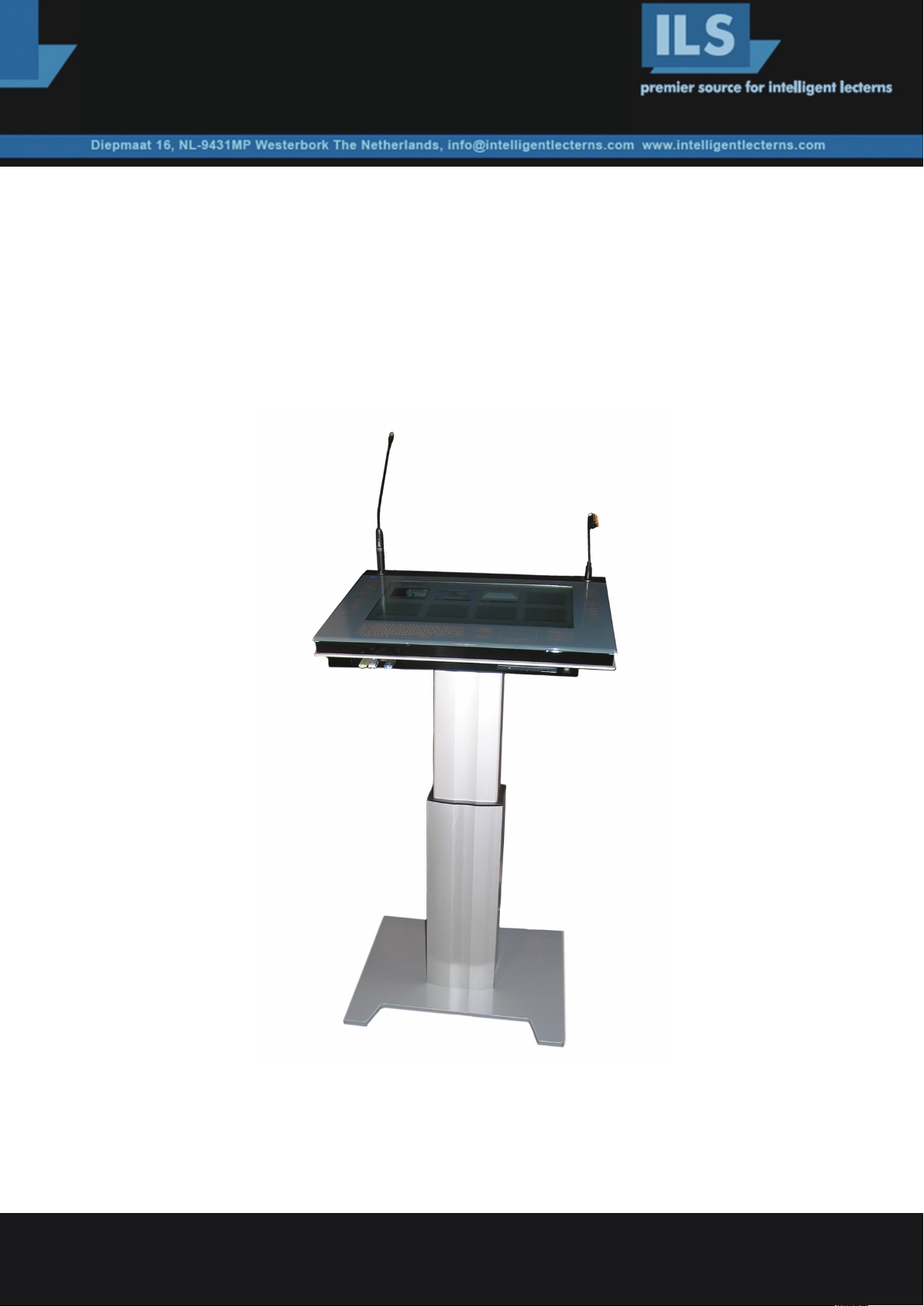
The ILS22G Lectern - User Set up guide.
status July 2009
ILS22G interactive lectern is a special product designed to use for presentations,
in particular Powerpoint presentations using the Sho-Q presentation delivery program.
Intelligent Lectern Systems BV Amsterdam / Westerbork / Mumbai / San Diego
write to enquiry@intelligentlecterns.com , call +31 593 568 015 (Henk de Groot)
Product specifications are subject to change. 081001EN
Page 2

Table of contents
Sho-Q / Preparing the ILS22G ........................................................................ 1
SOTouch ..................................................................................................... 2
Virtual keyboard .......................................................................................... 3
Communication ports and relays .................................................................... 4-7
Table 2 ..................................................................................................... 5
Microphones / PC ...................................................................................... 8
Touchscreen ............................................................................................... 9
Buttons .................................................................................................. 10 -13
Table 4 ..................................................................................................... 13
ILS22 Setup .......................................................................................... 14-15
ILS22 Setup Wizard .................................................................................... 16
Backlight controller .................................................................................... 17
Comm port open delay.................................................................................... 18
Remote control ......................................................................................... 19
Projector control ....................................................................................... 20-22
Pedestal control ........................................................................................... 23
Powerlift calibration................................................................................. 24 -26
ILS Translator setup .................................................................................... 27-28
Links and contact information .. ........................................................................ 29
Page 3

Congratulations with your ILS22G product.
If you received this product fully integrated and ready to go, launch sho-Q to start presenting.
Sho-Q
To start using sho-Q, you must connect a projector or external display to the ILS22G (VGA connector with converter or
DVI-D connector on the DVI-I socket provided).
You can then start sho-Q presenter and insert presentations, either through setting them ready with sho-Q Planner,
by using sho-Q presenter’s browser (press Manage Presentations, add) or by inserting a USB memory stick with a
Powerpoint presentation that has been exported with sho-Q Pre-processor.
Please refer to the sho-Q user manual.
With all presentations lined up on the sho-Q Presenter selector screen, one touch will start the presentation, simply
pressing next or previous slide, or select from view all slides… staged slides and embedded videos are controlled with
translucent buttons appearing within the current slide view frame, when needed. Better control of videos is offered when
sho-Q’s plug in for inserting video’s and flash files has been used (any sho-Q program automatically inserts Windows
Media Player in Powerpoint)
Sho-Q requires that MS PowerPoint or MS Office 2007 or 2003 has been installed.
Sho-Q is optionally expanded with a system to capture the presentation along with the video image of the presenter in a
virtual studio setting, in order to project the combined image in large auditoria. This is a unique productivity solution as
the XGA signal can stream real time over normal IP lines and be recorded at the same time.
Preparing the ILS22G
Using the right brackets, the ILS22G plateau may have been installed on the Powerlift electrical lift and foot, on the
ILS24 19” lectern cabinet, placed on any table or a custom designed podium.
On the front panel on the right of the DVD unit there is the power on button. After switching on the power, the ILS-logo
in blue must appear on the top left. Do not touch the system until it has finished completely its set up, marked by the fact
that the Room Control and Keyboard buttons are lit. Tap on the monitor field to see of the cursor is picking up your touch.
(When not, see end of next chapter)
Display: the ILS22G includes a 22” wide screen format display with 1680x1050 display resolution. For better reading
in the display panel has been placed “upside down” in the plateau, you may see it start up with a start up screen
that is upside down. The display panel is connected through the LVDS internal connector to the processor for the best
performance and control possible.
In case the display remains displaying upside down, then the INTEL GMA controller has been reset.
Open the display icon in the bottom right task bar tray and set the display at 180°
The operating system display settings must show the second display at its best resolution and set as extended desktop
device. (Right-click anywhere on the display and choose properties form the drop down menu. Select the settings tab.
Select 2nd monitor, set its resolution with the slide bar and tick the extended desktop mark)
1
Page 4

SOTouch
The ILS22G is equipped with a very advanced new patented acoustic touch detection system.
Because of this new technology, the design is remarkable: although the entire glass surface responds to touch technology,
there is no need for a bezel. The ILS22G uses regular tempered glass of narrow specifications.
The edges remain clear all around, any spilled water or coffee, any dirty finger marks can be cleaned with a regular
wipe and glass cleaner. Avoid pouring water over the top of the glass where it can seep between glass and aluminum
top with XLR sockets. The system is not entirely water-proof!
The top of the glass has been treated with the finest grain, to avoid that the presenter is looking at his mirror image.
The ILS22G touch implementation uses 2 sensors and detects locations from interference signals generated when the
glass is touched. The calibration process is simple and with this technology – after you are satisfied with the reach of the
touch – you never need to calibrate again.
The touch works with your finger or any object, provided the touch will generates vibrations within the glass.
You can place an object, for example a book, on the surface and the touch calibration remains unaffected.
When you change the resolution of the native screen the calibration is usually not affected, but if the screen ratio is
changed, you may need to re-start the program.
The touch system in static mode is ideally suited for operating the sho-Q Presentation delivery system.
In static mode drag and drop features can be used as well.
We recommend that you use this mode in general operation, but for instant touch needs - such as in presentation delivery
with PowerPoint or sho-Q - we suggest you disable the drag and drop feature.
This is done with a tick mark in the control panel of SO touch and eliminates the slight delay where the system is trying to
understand if a touch is the beginning of a trail or just a touch.
Normally you receive the system with SOtouch pre-loaded
2
Page 5
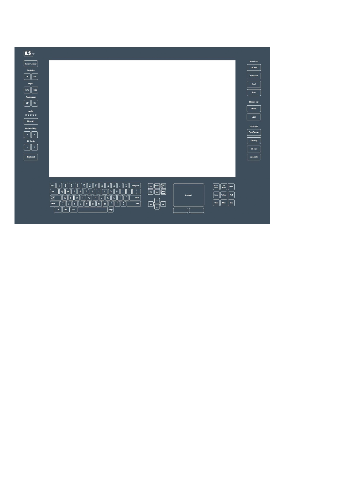
Virtual keyboard
The bottom of the glass is printed with a mask and buttons.
On the left side you will find the room control commands, on the right side there are buttons for source selection and
short-cuts. On the bottom area you’ll see a keyboard, directional keys, a mouse pad, and an annotation pad.
When a keypad is activated the LED’s behind the keypad are lit so that the keys become visible.
There are nine fields that can be individually programmed to be made visible.
Furthermore there are 5 level indicators that can be programmed, as well as signal areas for Projector, Touch, Mute and
PC audio. (see diagram 1 on the next page)
3
Page 6
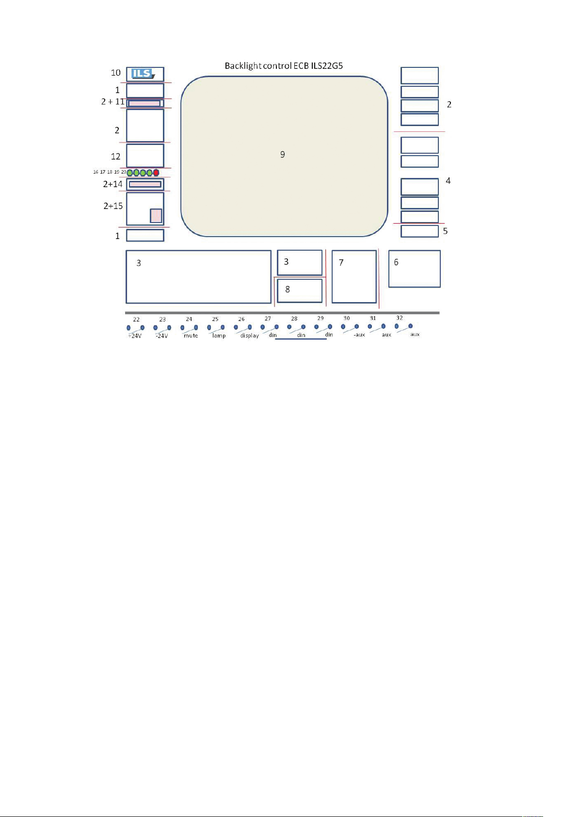
Diagram 1
In a normal setting almost all keys are invisible except for CONTROL and KEYBOARD (and ANNOTATION when this
feature is included in future versions). If you tap on these keys the rest of the buttons will become visible.
Tap again and they will extinguish and be insensitive to touch. Only lit buttons will respond to touch.
For operation and programming convenience the backlights are grouped by functional areas. (e.g. 2 for room control,
3 for keyboard, 4 for short cuts, 5/6 for annotation (for support in future system releases), 7 for the touch pad, 8 for
directional keys.
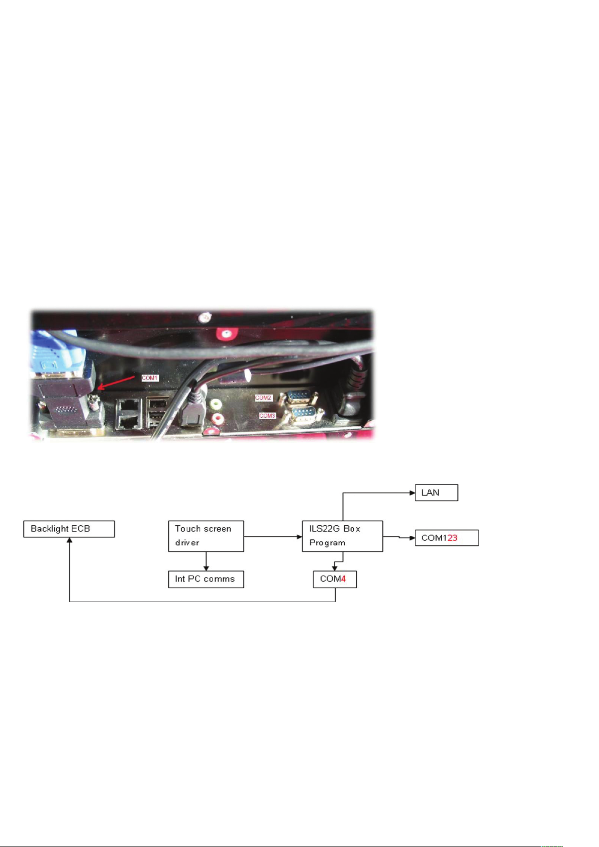
Communication ports and relays.
The ILS22 has 2 LAN ports, 4 COM ports (3 of which are on the outside) and 10 relays
(in 3 plugs 8 are externally reachable)
Just like the backlight LED’s, the relays are reached using the same protocol as for the backlight areas (see table 2)
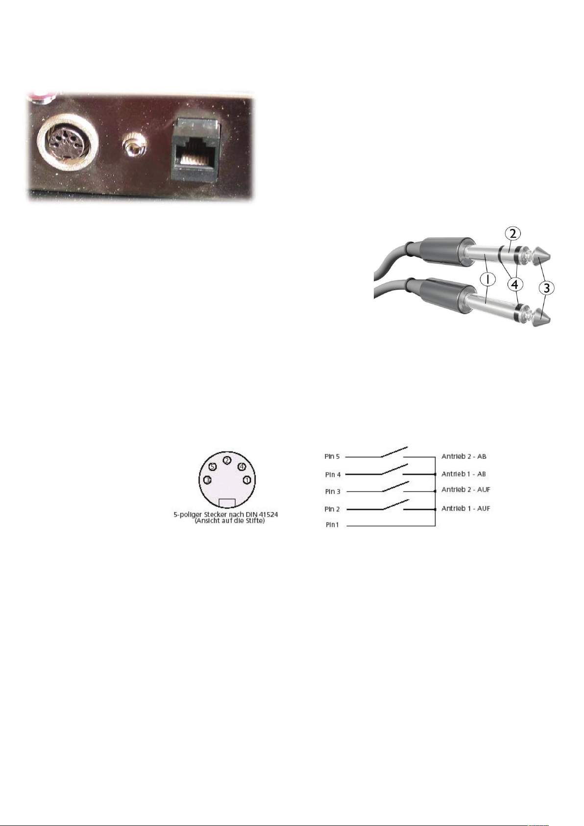
In the I/O bay you will find 3 sockets, RPT 1, a DIN plug socket, RPT2, a stereo jack, RPT3, an RJ45 RPT1, DIN plug
has pin 1 common and pin 2 or pin 3 to close the circuit.
This plug is intended for connecting to the electrical lift and operate the up & down control through the up and down
arrow on the keyboard (when keyboard and annotate are not active).
The commands for this plug are reached through address 22 and 23 resp. (pin 1 ground, Pin 2 = relay 1 or function
22, Pin 3 = relay 2 or function 23 )
4
Page 7

table 2
Commands backlight lector ILS
turn led on/off Initialization
Command: $xx_y? Change led dimmer frequency
Example: $02_2? Command: $F_xxx?
Meaning: leds of field 2 are dimmed Example: $F_007?
Meaning: Change the frequency of all the led dimmers
$ start sign
xx field number $ start sign
_ delimiter F frequency
y= 0 led off _ delimiter
1 led on xxx value for frequency (0-255)
2 led dimmed ? end of command
? end of command Frequency is calculated as follows:
Fields
01 Room control / Keyboard button frequency=1/( (xxx+1) / 152)
02 Room control field* xxx =152 * (1/f) -1 f=frequency
03 Keyboard
04 Display out and Shortcut fields Fill in the desired frequency 20 Hz
05 Annotate button
06 Annotation keys Value for xxx 7
07 Touchpad real frequency due to rounding 19 Hz
08 Arrow keys
09
10 Change duty cycle
11 Projector status red light Command: $Dxx_yyy?
12 Touchscreen field Example: $D05_179?
13 Touchscreen on (red) Meaning: Change the duty cycle of field 5 to 70%
14 Mute mic (red)
15 PC Audio + (red)
16 Audio L1 $ start sign
17 Audio L2 D Duty Cycle
18 Audio L3 xx field
19 Audio L4 _ delimiter
20 Audio L5 yyy value for Duty Cycle
21 Arrow up/down (green) ? end of command
22 Relay 1
23 Relay 2
24 Relay 3 Fill in the desired Duty Cycle 70%
25 Relay 4
26 Relay 5 Value for yyy 179
27 Relay 6
28 Relay 7 Real Duty Cycle due to rounding 69.92188 %
29 Relay 8
30 Relay 9
31 Relay 10
to 20 Hz
5
5
Page 8
RPT2, the stereo jack is issuing a +\or – 5 volt to switch the 2-way VGA switcher inside the ILS24G version with the
cabinet that includes a 4-way and a 2-way Extron switcher (but may also be used for other purposes)
The RPT3 RJ45 has 4 circuits on its 8 connectors that are opened
or closed by the relays for any need.
Do not apply more than 12 volts per pin pair!
The remaining 2 relays are for internal use (microphone mute
switch and optional light switch)
Socket layouts:
1. Sleeve: usually ground
2. Ring: Right-hand channel for stereo signals, negative phase for balanced
mono signals, power supply for power-requiring mono signal sources
3. Tip: Left-hand channel for stereo signals, positive phase for balanced
mono signals, signal line for unbalanced mono
signals
4. Insulating rings
3,5 mm jack plug stereo relay no: field protocol:
1= white wire = ground
2= brown wire = ring 3,4 24 & 25
3= green wire = tip
DIN plug 5 pins:
1= gray wire
2= yellow wire
1,2 22 & 23
4= pink wire
RJ 45 connector:
1= orange/white wire
2= orange wire
3= green/white wire
4= blue wire 6,7,8,9 27,28,29,30
5= blue/white wire
6= green wire
7= brown/white wire
8= brown wire
6
Page 9
XLR5: relay no: field protocol:
1= ground(shield)
2= switch ------------------- blue wire 5 26
3= negative signal-------------blue wire
4= switch --------------------white wire 5 26
5= positive signal--------------white wire
XLR3:
1= ground(shield)
2= positive signal-------------white wire
3= negative signal------------blue wire
Note: Reserve on connector P4 are relay numbers 10 &11 with respectively field protocols 31 and 32. Pin numbers P4 are 17,18
(relay number 10); 19, 20 (relay number 11). All commands are issued through the COM4 port.
COM1, COM2 and COM3 are available to hook up RS232 controllable devices, such as projectors or the 4-way
switcher inside the ILS24G 19”cabinet based version.
Next to the LAN network connector, the second LAN port can be used to connect to IP protocol driven control systems.
The flexibility in addressing and programming is endless.
However in our implementation we regarded mainly what functions are needed when one is standing behind the lectern.
eg. ‘Projector on’ may trigger the projector to start, but you could also combine that with issuing commands to close the
curtains, lower the screen and dim the lights.
Similarly the lights button is for having the lights up or dimmed, no matter how many bays of light switches are behind
that. We do not claim to control every possible light setting. If that is required, use the “Extra Buttons”-button to open
a room control application on the PC screen and use that to adjust the settings. This also applies if you require a local
language keyboard; just program that link to an OSK under the “Extra Buttons”-button.
Depending customer requests ILS may program more keys and function keys under the extra buttons.
7
Page 10
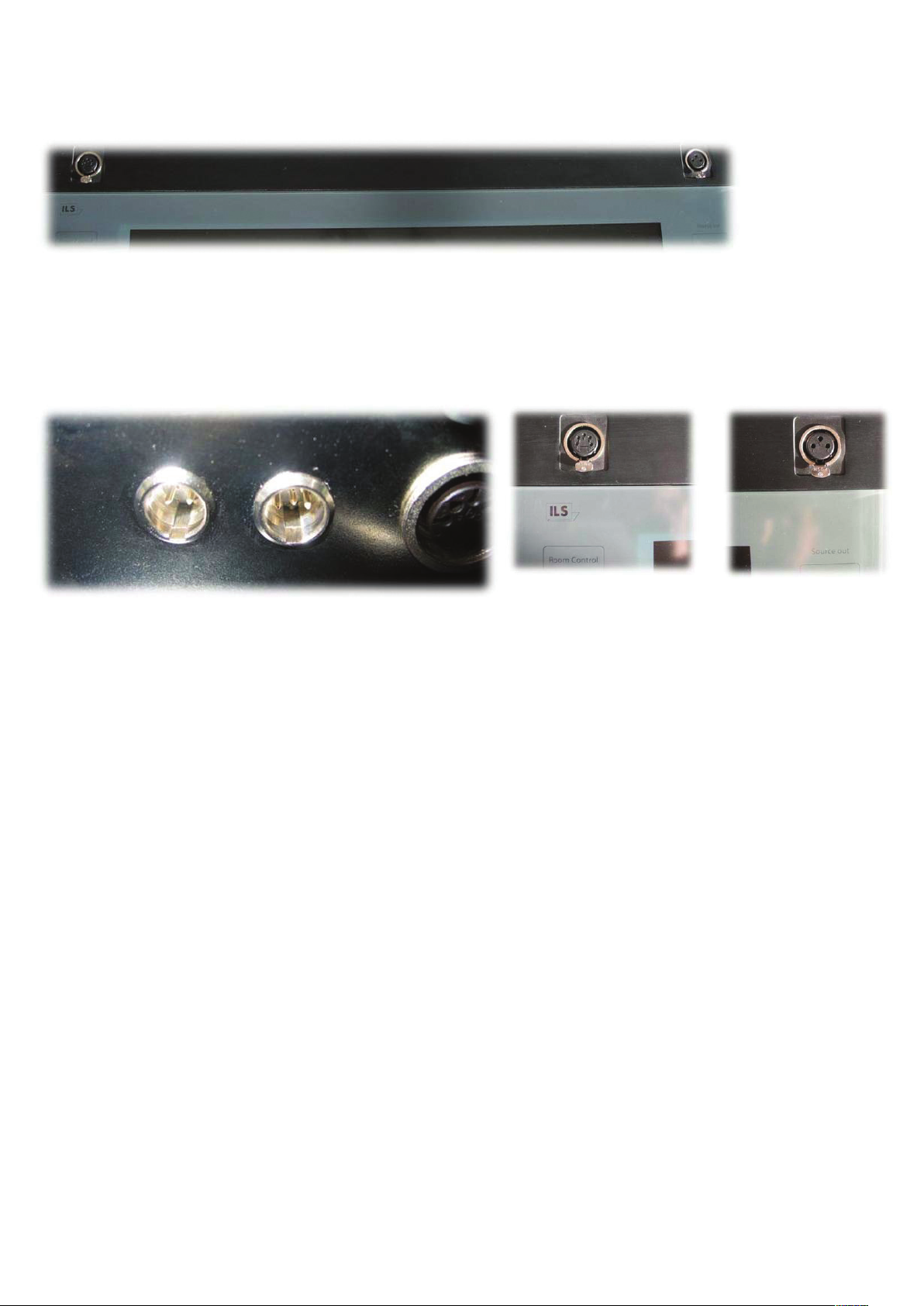
Microphones
The ILS22G provides 2 sockets for microphones.
On the left you find an XLR5 connector to which our optional microphone is connected.
This option consists ofs a high quality Shure condenser microphone with pre-amplifier. Due to its modification it can be
muted by touching the glass surface MUTE button on the left, and is thus brought under computer control (also possible
from a remote PC…) the connector to the amplifier is the corresponding miniXLR4m in the I/O bay.
The MUTE switch is executed by relay 5, field command 26.Mini XLR connections in the I/O bay….
On the right side is the XLR3 connector on which you place any microphone/phantom powered microphone with
external pre-amp and amplifier. The mute button can still be used to address such a microphone system provided there is
a way to connect over RS232, over IP, or through a relay.
PC
The internal PC power is based on an industrial motherboard with INTEL945 series board with
Core2Duo processor. This is a special board to provide the 4 COM ports and dual LAN with LVDS to the monitor and
DVI-I for flexible connection of display devices. On the front of the ILS22G you find 4 additional USB ports (and 4 in the
I/O bay), a multi format DVD player and the ON/OFF switch (hold 4 seconds before switching off to prevent accidental
switching)
The system comes with the Microsoft XP Professional 32-bit Operating System.
Optionally MS Office2007 will be added, but usually this is expected to be supplied and loaded by the client.
Sho-Q comes pre-loaded with the license key provided. If sho-Q Presenter is downloaded from www.sho-q.com and
installed by the client a “Sho-Q Evaluation Copy” banner will be visible on the output.
Instructions are provided in the software on how to obtain the license key to remove the banner in the output.
For further details, we refer you to the sho-Q user reference manual.
When you install your own MS Office software, please re-install sho-Q Presenter in order to insert the sho-Q plugins for
MS PowerPoint.
8
Page 11

Whereas the inner-side of the glass-plate functions as touchscreen for the LCD and the operating system, the outer sides
(left, bottom and top) contain engraved headers and buttons for additional functions, and the integrated keyboard.
These functions are available to the presenter if they are visible with the backlight turned on.
When the system initially starts-up, the Room Control, Mute Mic and Keyboard buttons are lit and can be used.
When starting-up the lectern PC, please wait for the system to start up and do not touch the screen until these keys are lit.
To familiarize the user with the possible functions, ILS has provided a default driver set. You can adapt the program to
suit your specific installation by adding or changing the pre-defined functions. With this version we have the modules
available, and can quickly do that programming for you upon request.
ILS also offers a user definable driver set via ILS22Setup.
When you start up the system for the first time, this will provide you with an easy way to define the way buttons are
going to be used. You can simply insert the communication codes via a Setup Wizard.
See the ILS22Setup Section for details.
9
Page 12

The Buttons.
keyboard
This key is located at the left bottom of the plate. Press this key to activate the keyboard buttons at the bottom of the
plate. This is useful when you need to enter a filename or other text in an application.
When you press this button, the keyboard backlight will come on and the keys will respond to touch.
Pressing the keyboard button again will disable the keyboard (the lights will go out).
Note 1: Via Extra Buttons/ILStranslator Setup one can define whether the keyboard and/or mouse functionality should
remain active if the Touchscreen buttons are turned off.
Note 2: The key marked Win, functions like pressing the start button in Windows XP and brings up the start menu.
Pressing it again will hide it.
Note 3: although a touch keyboard is not meant for regular writing of prose, users that require a local language
keyboard may bring up an on-screen keyboard from the accessibility folder of the PC, this can be started from the
keyboard button or extra buttons-function if you so desire.
room control
This key, located at the top left, is used to activate or de-activate keys on the left (system control) and on the right (input/
output control and additional functions). Which function buttons become available depends on the number of times the
key is pressed in a 1 to 5 sequence. See table 4 for an overview.
The 5th press turns the system back to its original state. This way the number of buttons a presenter might have to deal
with is limited. Usually only the keys that are needed within a presentation will be visible. Typically after set-up, the
presenter will only be confronted with 3 back-lit buttons: Control, Mute Mic and Keyboard.
Projector
off
This key group is used to directly control an attached projector from the system. The On key will send a command string
to turn the projector on, the Off key will shut the projector down. The Projector header can be pressed to send an inquiry
command string, e.g. for requesting current lamp hours or power query. The command strings can be send over a serial
(RS232) connection. Alternatively, strings can be send to a serial attached intelligent controller, such as from EZcontrol,
Extron, AMX or Crestron. In the standard version, these keys are NOT defined, as they are dependent on manufacturer
and model. However, this can be set via the also supplied ILS22Setup program.
on
10
Page 13

Lights
low
high
This group of keys is aimed to control the room lighting conditions. If an intelligent room controller is attached (RS232)
the keys can be programmed to send a command string to the controller. The Lights header can be used for another
function, e.g. screen down for the projector. In the standard version, these keys are NOT defined. However, this can be
set via ILS22Setup.
Touchscreen
off
on
After a 1st press on Room Control, these functions become available. In some cases, it might be required to turn the
glass-plate buttons off, e.g. when a presenter wants to present from paper on top of the glass without risking accidentally
executing functions. When the touchscreen is disabled (press the Off key), all other keys are disabled and the light
behind the keys will blink in a 2 second sequence. The ONLY key that will respond in this mode is the On key.
The Touchscreen header can be pressed (functions as a toggle) to turn the light behind on or off.
Audio
The audio group consists of a header and 5 led’s (4 green, 1 red), which can emit light in two stages, e.g. light green
and darker, light red and darker, indicating the master audio level of the build-in mixer. The master volume is indicated in
a range from 0 to max, e.g. all off or all on (including the red LED) on a 0-100% basis. A setting of 50% results in first 2
green led’s full on, 3rd LED light green. The Audio header functions as a toggle to show or hide the volume setting.
Note: The audio volume can be adapted under the PC Audio group, see further in this document.
Note: When the Touchscreen is OFF, the LED’s in earlier versions, get another meaning. The red LED indicates that the
internal (Shure) microphone is muted, the green LED next to it indicates the mic is not muted. See next paragraph.
Note: A blinking red LED indicates the PC Audio master volume is muted. See the PC Audio group description below.
mute mic
The Mute Mic key is to mute/un-mute the so called Internal microphone connected to the top left socket (as opposed
to a loop-through microphone connected in the top right socket). When pressed the backlight will blink to indicate
the microphone is muted. Press again to un-mute. The microphone control functions are re-programmed to address an
external amplifier controller when the XLR sockets are connecting microphones straight to an external amplifier without a
local pre-amp in the microphone foot for local on/off control.
How the Mute Mic button is functioning is set via ILS22Setup.
11
Page 14

Mic sensitivity
-
+
Intended to increase or decrease the internal microphone level or bias setting. In the standard version, these keys are
NOT defined. The Mic sensitivity header functions as a toggle, showing or hiding the master volume setting (see also
next paragraph). Via ILS22Setup one can define how and with which communication setting Microphone volume is
controlled by en external controller.
PC Audio
-
+
Increases/decreases the master volume of the build-in mixer. With these keys the presenter can locally adjust the volume
output of the system. On a 0-100% basis, the audio level is indicated by the 5 LED’s (4 green, 1 red) under the Audio
group. See earlier in this document. The PC Audio header functions as a master volume mute/un-mute toggle.
When pressed the master volume is muted. The muted state is indicated by a blinking red LED under the Audio group.
Press again to un-mute.
Note: Although the master volume may be muted, the LED’s still indicate the audio output volume level.
Source out
Lectern
Notebook
Aux 1
Aux 2
This group of keys is intended to select the output source, whether the Lectern System, an external connected notebook
PC or Auxiliary devices such as DVD player or other devices. Lectern is used by default. If an intelligent external switch
controller is connected (via RS232), command strings can be send to the controller. In the standard version, these keys
are NOT defined, as they are dependent on manufacturer and model.
Note: Functional behaviour of the keys is defined via ILS22Setup.
Display out
Mirror
Span
This group of keys sets up the external display or projector. Mirror will show the same image as on the system display,
Span will extend the system desktop to the connected projector or external display.
In the current version, these keys are NOT defined. The Display out header key will bring up the embedded graphics
controller interface, so that extended desktop or mirror can be set up manually.
(Procedure details: to switch settings you must first assign the same resolution of the external graphics display port to the
internal monitor. After applying that, you can make the switch AND set or reset the screen orientation; the internal monitor
is set to 180° rotation)
12
Page 15

The Display out header key will bring up the embedded graphics controller interface, so that extended desktop or mirror
can be set up manually.
(Procedure details: to switch settings you must first assign the same resolution of the external graphics display port to the
internal monitor. After applying the setting, you can make the switch AND set or reset the screen orientation; the internal
monitor is set to 180° rotation)
shortcuts
extra buttons
desktop
sho-Q
The shortcuts group provides a quick manner to activate additional functions. The Extra Buttons key will bring up a
window on the LCD screen with additional touch buttons. The Desktop key will show the desktop by minimizing all
windows into the taskbar.
Note: When Sho-Q Presenter software is running, this key will bring up the taskbar.
The Sho-Q key will start up Sho-Q Presenter software. Although normally Sho-Q is started with system startup (via a
shortcut in the start menu), this key can be used if Sho-Q was stopped and needs to be started up again.
The Shortcuts header key emulates an Alt + Tab keyboard entry to quickly jump from one program window to the next
one.
Annotate
The Annotate key activates the annotation keys in the bottom right part of the glass-plate. In the standard version,
these keys are NOT defined. An implementation is planned once a software update is made available for the touch
technology to include drag & drop capability.
Functions becoming available and being activated after a number of Room Control key presses, when using the default
set up:
Number of Room
Activated group of keys Remarks
Control presses
0 zero state Room control key, Mute mic,
Keyboard key
1 limited action Touchscreen group, Audio group Ability to turn Touchscreen off
2 setup mode Projector group, Lights group,
Mic sensitivity, PC Audio, Source out
3 expert mode Shortcuts
4 future mode Annotate
5 zero state Room Control key, Keyboard key System startup condition
System startup condition
Table 4
13
Page 16

ILS22Setup
The program to configure your ILS22 with ease.
Introduction.
As the name of the program suggests, ILS22Setup gives the end-user the opportunity to program the behaviour of the
ILS22 with respect to the control functions. The control functions are located to the left, bottom and right of the system
LCD screen, and they are engraved on the glass plate.
Simply put, the ILS22 glass-plate buttons and headers can be used by the presenter, end-user or supporting technicians to
execute commands directly (e.g. startup the Sho-Q Presenter package), enable or disable keyboard entries, increase or
decrease system audio volume output etc. By pressing the Touch Screen Off button one can temporarily disable all these
keys (until the On button is pressed). This is handy when presenters use the surface for other purposes than presenting.
The ILS22 and embedded functions in general can control:
• An attached projector. Power On, Power Off, or definable commands for example inquiring power status
or lamp hours.
• Room light condition. Turn light higher or lower.
• Audio volume. Higher or lower or mute.
• Microphone volume, mute/un-mute.
• Display out selection, either Lectern itself or attached devices such as Notebook or auxiliary.
• Electrical pedestal elevation up/down.
All of these functions depend on the embedded system software driver which is called ILStranslator, and the setup as
defined through ILS22Setup.
There are 3 possibilities per control function:
• The ILS22 will do it. Internal software in ILStranslator, internal relays and direct communication (RS232) to external
devices are under direct control of the ILS22.
• The ILS22 has nothing to do with it. Glass-plate touches have no effect, external devices and circuitry is used.
• The ILS22 is setup as an intermediate or user-interface. Glass-plate touches will be translated into commands to external
intelligent controllers which will perform the requested action.
ILS22Setup makes the lectern a hybrid system. You can choose and match according to local conditions and
requirements:
• Select which device is taking the action.
• Define communication parameters.
• Which keys are programmed for action.
• Enter the ASCII command strings you want for external control.
• Which relays in the system are used.
14
Page 17

The following schematics show how all components work together :
The ILS22Setup wizard is used to determine which peripherals are under direct control of the ILS22, which peripherals
are controlled via external intelligent controllers, which communications settings and command strings are used to address
peripherals and controllers, and whether remote control (for instance via Remote-Q or other controllers) is enabled.
The ILS22Setup wizard is saving all this to the lectern system’s registry.
At start up, ILStranslator will read the registry. If ILS22Setup was not used during installation, ILStranslator will use the
default values. The SOTouch driver determines which glass plate buttons or header were pressed, and passes this on
to ILStranslator. In turn, ILStranslator will ‘translate’ this to embedded system functions or pass it on to attached intelligent
controllers, or react to external controller supplied commands.
The ILS22Setup Wizard will guide you through the possibilities. Each form will show what the default factory setting is.
15
Page 18

The ILS22Setup Wizard.
The ILS22Setup program when first started, will show up as a XP-like Microsoft Wizard.
If ILS22Setup was executed before and parameters were saved to the system registry, the following form comes up:
In order to change the Setup, press Edit Settings (Alt-E).
The wizard is self-explanatory, but we will continue with some examples.
Note: Moving the mouse pointer over a button, option, check box or text entry field will bring up related tool-tip-text.
16
Page 19

Backlight controller
When the ILS22 is delivered in a standard setup, an internal PC is used to control the system and the backlight and
relays controller. The internal PC has 4 serial comm ports, of which COM4 is used to communicate with the backlight
controller (see above scheme). In situations where an external PC is used, ILStranslator needs to know to which serial port
will be used to address the backlight controller inside the ILS22.
Note that only the serial port can be changed. The other communication parameters are fixed.
17
Page 20

Comm Port open delay
Whether or not the backlight and relays controller is connected to the internal or to an external PC, the comm. ports needs
some time after an open comm port command.
In the above form you can specify the number of milliseconds to wait before the comm. port gets active after opening it.
If the internal PC is used, comm. ports may open successfully in just 250 milliseconds. With an external PC it may take
longer. This entry allows to fine tune the system and has an impact on the ILStranslator start-up time.
18
Page 21

Remote control.
If you want ILStranslator to also listen and allow control besides the direct glass plate buttons, keep that possibility open
by selecting the second option.
Note: Select the second option if you also obtained Remote-Q.
Select which Comm port on the ILS22 you want to use and the Baudrate to operate at.
The default value is 19200 baud, but here you can increase that depending on your remote control hardware
capabilities.
Note: With a modern PC or laptop you should be able to successfully communicate at 115200 baud or higher.
19
Page 22

Projector control.
The projector control form allows selecting which device is controlling the projector concerning power on, power off
or inquiry.
Select the first option if the projector is under direct control of
the lectern.
Select the second option if the lectern has nothing to do
with it, e.g. the projector functions are under direct control
of a supplier supplied IR remote or a controller board room
interface.
Select the third option if the lectern has to send out a command
string to a connected intelligent controller.
Selecting option 1 or option 3 allows you to enter the communication parameters as shown in the
following picture.
Note that COM3 and COM1 were already reserved
for Backlight controller communication and for remote
control in this special configuration. If no remote
control was desired (keep the option open), both
COM1 and COM2 would be available.
In the standard ILS22Setup with internal PC,
communication to the backlight controller is via the
internal PC COM4 port, leaving COM1, COM2 and
COM3 available for other connections.
20
Page 23

The check boxes allow specifying whether the glass plate buttons are activated (check the box) or not activated (un-check
the box).
In the Command string text boxes you can enter the ASCII strings to be send out to the projector to perform the function.
In this example, the InFocus CLI command structure is used. (PWR1) ,enter as text without quotes, will power up InFocus
projectors, (PWR0) will shut it down. A (LMP?) inquiry via the header will request lamp hours.
Some protocols require a trailing character to indicate the end of the command. Select under Trail chars (the InFocus
projectors require none).
The bottom half allows to specify the communication setting. Select the Comm port to be used on the ILS22, baud
rate, parity, number of data bits, number of stop bits and communication handshaking. People familiar with Windows
embedded Hyperterminal should recognize the choices.
Instead of being under direct control, the ILS22 can be set up to control projectors via an attached controller capable of
receiving command strings over a serial RS232 communication line.
This form is representative for the remainder of this user guide:
• Either control is directly via the ILS22 Lectern (actually via ILStranslator)
• Control is performed via external circuitry (externally)
• Control is performed with ILStranslator functioning as a user interface to an attached intelligent controller
21
Page 24

If attached to an intelligent controller, and ILStranslator is functioning as a user interface, you can specify which buttons
are active, which commands to send and where to send them to.
The next item to configure is Projector control via an attached intelligent controller, this also applies to:
• Room light control (Lights)
• Mute Mic control (Mute Mic)
• Mic Volume control (Mic sensitivity)
• Master Volume control (PC Audio)
• Switch control (Source out)
If all of these functions you specify are to be done without interaction with ILStranslator, or ILStranslator as user interface,
choose the second option which directs commands to be performed or controlled ‘externally’. In that case, ILStranslator
will not backlight these buttons.
In the String command text boxes you can define which ASCII
text string is send to the attached
controller. The controller will receive these commands and
translate them into action for the projector connected to the
controller.
In this example the intelligent controller will, after pressing the
Power on button on the ILS22
glass-plate, receive the string ‘C3’, without the quotes as
indication to power on the projector.
The controller will translate that into the correct command and
perform the task of powering on.
In this example the check box for the Projector header is unchecked, so no action will be taken
after pressing the projector header on the ILS22 glass-plate.
22
Page 25

Pedestal control.
If the ILS22 is mounted on an electrical pedestal (the ILS Powerlift), it can be elevated up or down .
The ILS22 has build-in relays for control functions.
By default, relays 22 and relays 23 are reserved for driving the motor in the optional electrical pedestal from ILS
(supplied with the ILS22G).
One can define the number of seconds the relays will be closed (number of seconds for up/down movement).
Default is 2 seconds.
If under direct control of the lectern (ILStranslator), the following form will show up.
Via Powerlift Calibration you can specify (‘Mark’) the lowest setting, which in turn will be used to provide a calculated
indication in ILStranslator (and Remote-Q) what the current height is calculated in cm’s and inches.
This calculated indication is shown in ILStranslator/Extra Buttons.
23
Page 26

Powerlift Calibration
Select the first or third option to calibrate the Powerlift.
After verifying that the comm port to the backlight/relays controller is free for communication, the following form will show
up (if not, a window will appear where you can to stop ILStranslator or an other program that is communicating over the
comm port):
24
Page 27

The form shows the approximate lowest and highest position measured in centimeters (in this case 89 cm as the lowest
setting, and 114 cm as highest). The positions are measured at the front (Presenter side) from ground up to the top of the
pedestal.
Note: There might be later Powerlift engines which go lower or higher, or have a different rise-time from lowest to highest
measured in seconds (current Powerlift installations go from 89 cm at the lowest setting, to the highest setting at 114 cm
in roughly 17.5 seconds). If in doubt, use Alt_A or the menu Adapt entry to change your findings.
If you are presenting at the ILS22 lectern, you can press the Down button in this ILS22Setup wizard until the motor stops
and the lectern can’t go any lower. Based on the measured lowest position, you can adjust lowest, highest and rise-time
values. Press the Mark lowest button and the following form will come up to allow you to adjust to an initial height.
Press the Down or Up buttons to elevate the pedestal into a required
default position. The approximate height values will be adjusted
accordingly.
Press the Next button to continue.
25
Page 28

At the end of the wizard, an overview of the settings you entered will be provided.
Press the Save and exit button to save the settings to system registry.
If you would like to adjust the settings Press the Again button to restart the Wizard.
When ILStranslator is started up, it will read the ILS22Setup settings from the registry and act accordingly.
Note: Within ILStranslator, these settings can not be changed. Therefore, restart ILStranslator if changes were made in
ILS22Setup, and you want them to take effect.
Note: To configure the ILS according to your preferences, you only need to run the ILS22Setup Wizard once
26
Page 29

ILStranslator Setup.
Via the Extra button (when lighted on the glass-plate) a Windows form will pop up with extra functions and control
possibilities.
Task Mgr will bring up the Windows Task Manager (so that applications can be stopped or users can log off).
Keyboard will bring up the embedded software keyboard for local language requirements.
Windows start Open and Close will open/close the Windows start menu.
Pedestal elevation will move ILS22 up or down when mounted on an electrical pedestal.
In the ILStranslator section, the Debug button will bring up a small form which allows tracking of instructions received and
strings sent to the internal backlight controller or externally connected devices.
Hide will hide the Extra buttons form in the taskbar.
End will end the ILStranslator program and turn all back lighted buttons on the glass-plate off.
After ending ILStranslator, the glass-plate buttons can no longer be used.
The Setup button will bring up a new Windows form which allows altering some of the system behaviour functions.
27
Page 30

If a user chooses to turn the Touch screen off, none of the glass-plate buttons will be lit nor will any of the buttons function,
except for the Touch screen On button. This key will blink to indicate the touch screen is off.
To prevent any keyboard action from an attached (external USB) keyboard or (external USB) mouse interrupting
presentations, e.g. if the surface is used for paper presentations, Windows mouse and keyboard functions can be
disabled by checking the boxes. Do not disable the mouse if you want to advance slides in Sho-Q presenter.
If an external controller or other device (e.g. projector) is connected to the system, users may want to see (temporarily) the
reply of such devices on a command string sent. The duration set will define how long the reply will remain visible.
Check the Audio mute by software box if you do not want to use the mute function of the hardware mixer or if you are
experiencing un-mute problems. In presentations using audio, this has the effect of sliding the master volume back to 0 in
discrete steps. This is useful for fading down audio in presentations. Un-muting will bring the original volume back on.
Note: Audio mute is performed by the PC Audio header if set so in ILS22Setup.
By hitting the Apply key (Alt-A), the changes will go into effect and the new settings will be saved to system registry.
When ILStranslator is started up, these settings will be read and active.
ILStranslator Remote commands overview.
Please refer to our WEB site for the latest overview published in an Excel spreadsheet.
28
Page 31

For other detailed information consult:
Sho-Q user reference manual, for latest status, see www.sho-q.com
SO touch reference manual, for the technology see www.sensitive-object.com
ILS22 software releases www.intelligentlecternsystems.com
IL22 remote commands overview www.intelligentlecterns.com
ILS22 user guide updates www.intelligentlecternsystems.com
Below is an artist impression of ILS22 Remote-Q program, which allows to control the ILS22 from a remote PC or ILS15.
This program is optionally available.
Contact enquiry@intelligentlecterns
Intelligent Lectern Systems BV Amsterdam / Westerbork / Mumbai / San Diego
write to enquiry@intelligentlecterns.com , call +31 593 568 015 (Henk de Groot)
Product specifications are subject to change. 081001EN
29
 Loading...