

Page 1

Illustra Pro LT 2MP Bullet
Illustra Pro Compact Mini-Bullet
Quick Start Guide
8200-1136-01 A0
Page 2

Page 3

Notice
The information in this manual was current when published. The manufacturer reserves the right to revise
and improve its products. All specifications are therefore subject to change without notice.
Copyright
Under copyright laws, the contents of this manual may not be copied, photocopied, reproduced, translated or
reduced to any electronic medium or machine-readable form, in whole or in part, without prior written
consent of Tyco Security Products. © 2015 Tyco Security Products. All rights reserved.
Customer Service
Thank you for using Tyco Security Products. We support our products through an extensive worldwide
network of dealers. The dealer through whom you originally purchased this product is your point of contact if
you need service or support. Our dealers are empowered to provide the very best in customer service and
support. Dealers should contact Tyco Security Products at (800) 507-6268 or (561) 912-6259 or on the Web
at www.illustracameras.com.
Trademarks
The trademarks, logos, and service marks displayed on this document are registered in the United States [or
other countries]. Any misuse of the trademarks is strictly prohibited and Tyco Security Products will
aggressively enforce its intellectual property rights to the fullest extent of the law, including pursuit of criminal
prosecution wherever necessary. All trademarks not owned by Tyco Security Products are the property of
their respective owners, and are used with permission or allowed under applicable laws.
Product offerings and specifications are subject to change without notice. Actual products may vary from
photos. Not all products include all features. Availability varies by region; contact your sales representative.
i
Page 4

Notice of Use
This manual is designed for administrators and users of the network camera. Please read it carefully before
use. All requirements should be followed before using this camera.
We are not responsible for any technical or typographical errors and reserve the right to change the product
and manuals without notice.
Keep this document for future reference.
It is intended that this camera utilizes a PoE power source that complies with LPS requirements.
The camera must be installed on a solid mounting surface.
Keep the camera and other accessories dry.
We are not responsible for any damage caused by inappropriate use.
Safety Notice
The recessed indoor camera models are rated as suitable for use in environmental air handling spaces, except inside
air ducts or furnace plenums
ESD Precautions: With the covers removed during installation and alignment this product is sensitive to electrostatic
discharge. The installer should take appropriate ESD control measures such as the use of a ESD wrist strap
connected to the chassis of the camera.
Note to Installer - POE networks that are connected to IP Encoders should not be routed to the exterior or
outside of the installed plant location.
ii Quick Start Guide
Page 5

Features
ADCi610-M022
IPL02B1BNWIY
IPL02B2BNWIY
Motion detection
Motion detection
High quality compression in real time
streaming
High quality compression in real time
streaming
Full frame rates @ Maximum resolution
1920x1080 provides superior image
quality
Full frame rates @ Maximum resolution
1920x1080 provides superior image
quality
Supports simultaneous streaming of
H.264 and MJPEG encoded video
Supports simultaneous streaming of
H.264 and MJPEG encoded video
Wide Dynamic Range (WDR)
Wide Dynamic Range (WDR)
Backlight Compensation
Backlight Compensation
Digital Slow Shutter
Digital Slow Shutter
IR Illuminator
IR Illuminator
Dynamic 2D Digital Noise Reduction
Dynamic 2D Digital Noise Reductio
OSD supported
OSD supported
Weather Proof (IP66)
Weather Proof (IP66)
Event or Continuous recording on
microSD card or FTP(microSD media not
included.)
Event or Continuous recording on
microSD card or FTP(microSD media not
included)
PoE supported
PoE supported
ONVIF 2.4 Profile S compliant
ONVIF 2.4 Profile S compliant
Remote zoom and focus control
Analogue Video Output
Digital Input / Output
Product Features
Product Features
1
Page 6
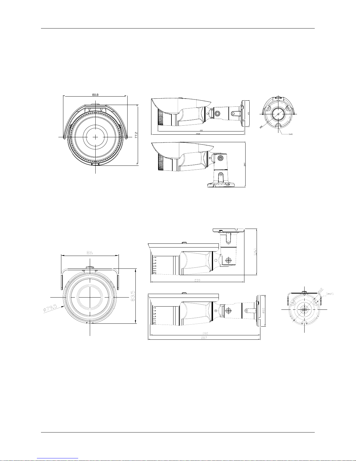
Product Features
( Unit: mm )
( Unit: mm )
Dimension ADCi610-M022
Dimension IPL02B1BNWIY
IPL02B2BNWIY
2 Quick Start Guide
Page 7
Product Features
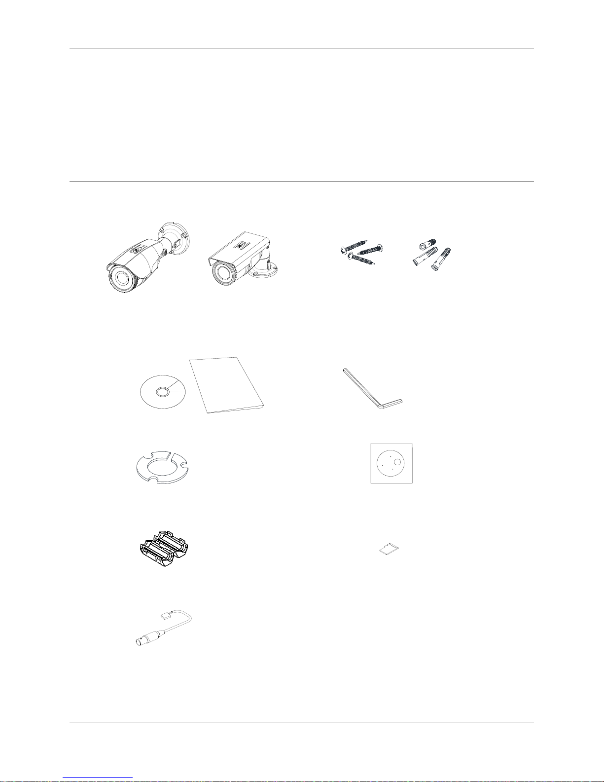
Camera x 1
Mounting screw with plastic anchors x 3
ADCi610-M022 IPL02B2BNWIY
Quick installation guide & CDROM x 1
Hex Wrench Driver
Silicon Waterproof Band
Paper Mounting Template x 1
Ferrite Core (ADCi610-M022)
microSD card (pre-installed exclusively in the
camera model, IQS02MFONWTY)
Video Output Cable (IPL02B1BNWIY & IPL02B2BNWIY )
Package contents
The package contains a camera, screws, anchors, a waterproof band, a ferrite core, a hex wrench
driver, universal plugs, a quick installation guide, a CD ROM, a paper mounting template, and a
microSD card (exclusive for the camera model, IQS02MFONWTY). Unpack the package carefully, and
handle the equipment with care.
Note:
The contents of the package may vary by model:
3
Page 8
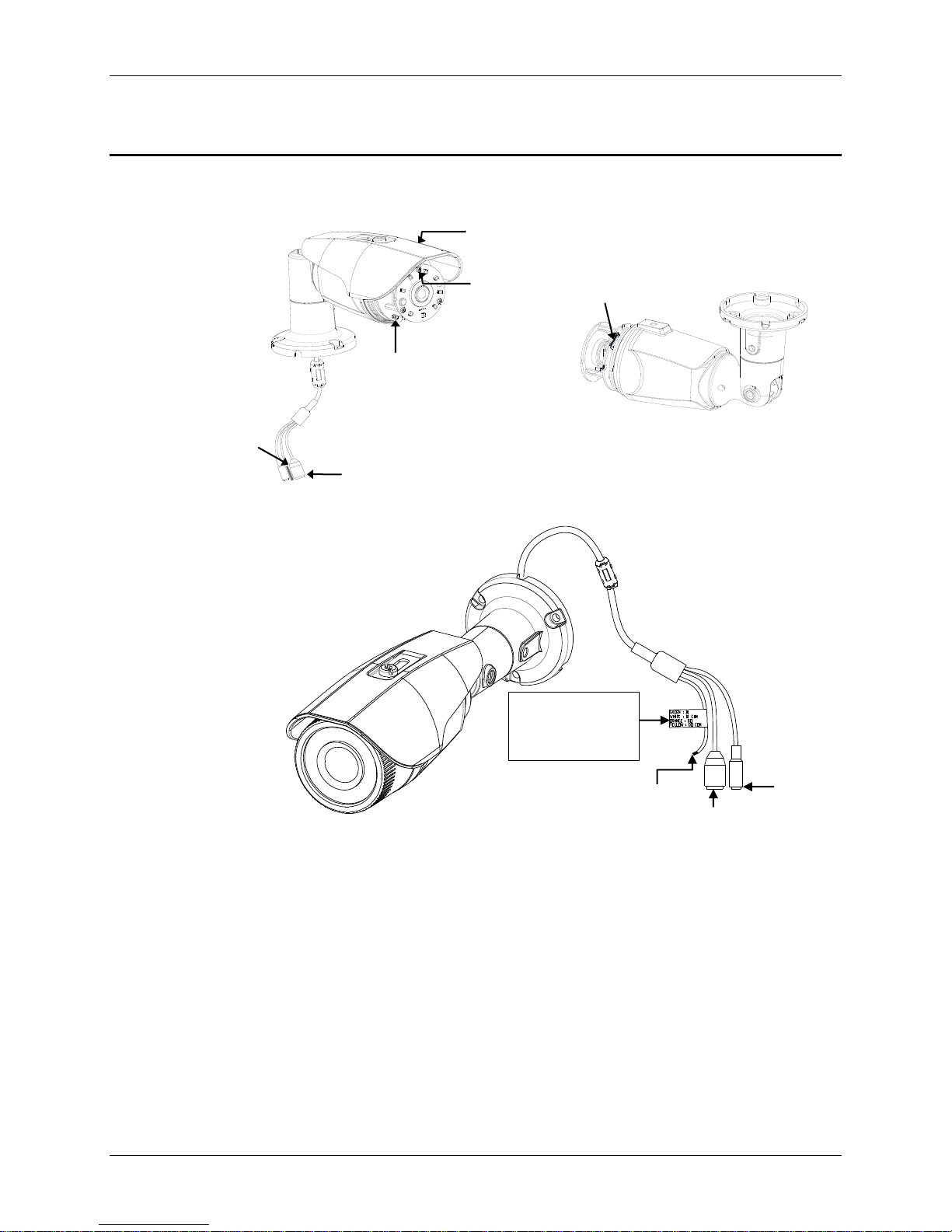
Controls/Connectors
GREEN: DI
WHITE: DI COM
ORANGE: DO
YELLOW: DO COM
Terminal
Connector
LAN
Connector
Power
Connector
LAN Connector
Reset button
microSD / SDHC/ SDXC card slot
Terminal Connector
Sunshield
CDS Light Sensor
ADCi610-M022
Controls/Connectors
4 Quick Start Guide
Page 9
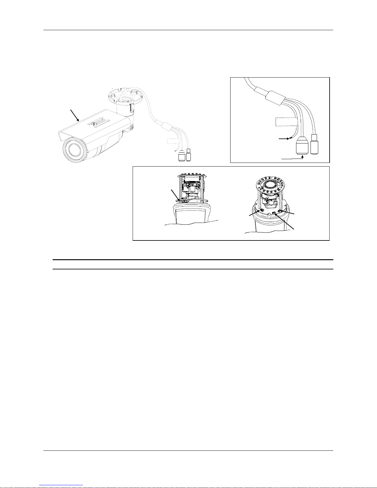
IPL02B1BNWIY
Video Out
PAL/NTSC
Reset
SD Card
Reset button
PAL/NTSC button
Video output
Cable socket
Terminal Connector
LAN Connector
Sunshield
microSD/SDHC/
SDXC card slot
IPL02B2BNWIY
Controls/Connectors
Note
Models herein and their appearance are subject to change without any prior notice.
Sunshield: Protects the camera lens against direct sunshine.
Reset button: This button will restart or reset to factory default settings. Refer to Reboot or Factory
Default under the Maintenance section in the camera’s Installation and Operation Manual for more
details.
CDS Light Sensor: To detect the level of ambient light or intensity of light. The sensor should not be
blocked by a cable or any other objects.
microSD/SDHC/SDXC card slot: The camera supports up to 64GB. Class 4 or higher SD card is
recommended for HD recordings.
Terminal Connector: Cable connections for digital input/output. Refer to Connections in the
camera’s Installation and Operation Manual for more details.
LAN connector: RJ45 LAN connector for 10/100 Base-T Ethernet.
5
Page 10
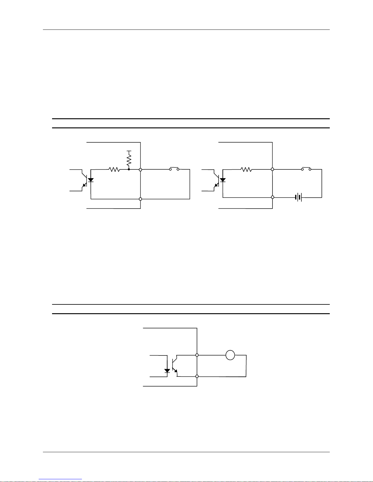
Controls/Connectors
DO
COM
Relay Type
Device
Internal
+3.3V
DI
COM
DI
COM
+
-
Relay Type
Voltage Type
+
-
Output of
Sensor
Output of
Sensor
Internal
Internal
+
-
Peripheral Connection
Sensor (DI) Connection
Sensor(DI) can be connected to either a voltage type sensor or a replay type sensor like in the
following figures. Settings can be done through the camera’s webpage.
Input voltage range: 0VDC minimum to 5VDC maximum, Max 50mA
CAUTION
Do not exceed the maximum input voltage or relay rate.
Alarm (DO) Connection
Only the replay type is supported.
Relay Rating: Max 24VDC 50mA
The activation can be managed through the camera’s webpage. (IPL02B2BNWIY)
CAUTION
Do not exceed the maximum replay rate.
6 Quick Start Guide
Page 11

Controls/Connectors
-
+
Power Connection
The camera can be powered from either 12VDC or PoE. If it is powered from 12VDC, connect an adaptor
which can supply the camera with enough power. Also, refer to the characteristics of the polarity according
to the image below.
LAN Connection
The LAN connector is an RJ45 LAN connector for 10/100 Base-T Ethernet. Use the Ethernet cable (RJ45)
to connect the device to a hub or a router in the network.
.
7
Page 12
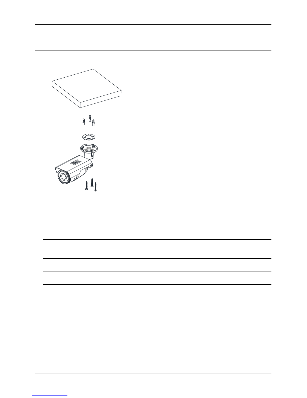
Installation
Model Shown IPL02B2BNWIY
Installation
1. Place the paper mounting template that is included in
the package on the desired installation surface.
2. Drill three holes in the correct positions based on the
paper mounting template, and insert the plastic anchors
into the holes.
3. Attach the silicon waterproof band included in the
package to the camera’s mounting surface by aligning it
with the three alignment holes on the camera’s mounting
surface.
4. Connect the required cables to the device. Refer to
Connections in this manual for more details.
5. Place the camera body on the mounting surface to
match its alignment holes with the corresponding plastic
anchors.
6. Tighten the plastic anchors with the screws through the
camera’s alignment holes.
7. Adjust the heading direction of the camera. Refer to the
section, ‘Adjusting angle of the camera’ for more details.
8. Attach the lens cover to the camera by rotating it
clockwise.
9. Adjust zoom and focus of the camera. Refer to the
section, ‘Adjusting zoom and focus’ in this manual for the
instructions.
CAUTION
Sealing gaps is recommended as gaps may appear after the camera installation. Gaps may cause
problems such as moisture, water leakage, and etc., which negatively affect the operation of the
camera if gaps appear but remain unsealed.
CAUTION
To prevent products from damage, place the camera on stable and non-vibrating surfaces If the
stability is in doubt, consult safety personnel for reinforcements, and then proceed with the installation.
8 Quick Start Guide
Page 13
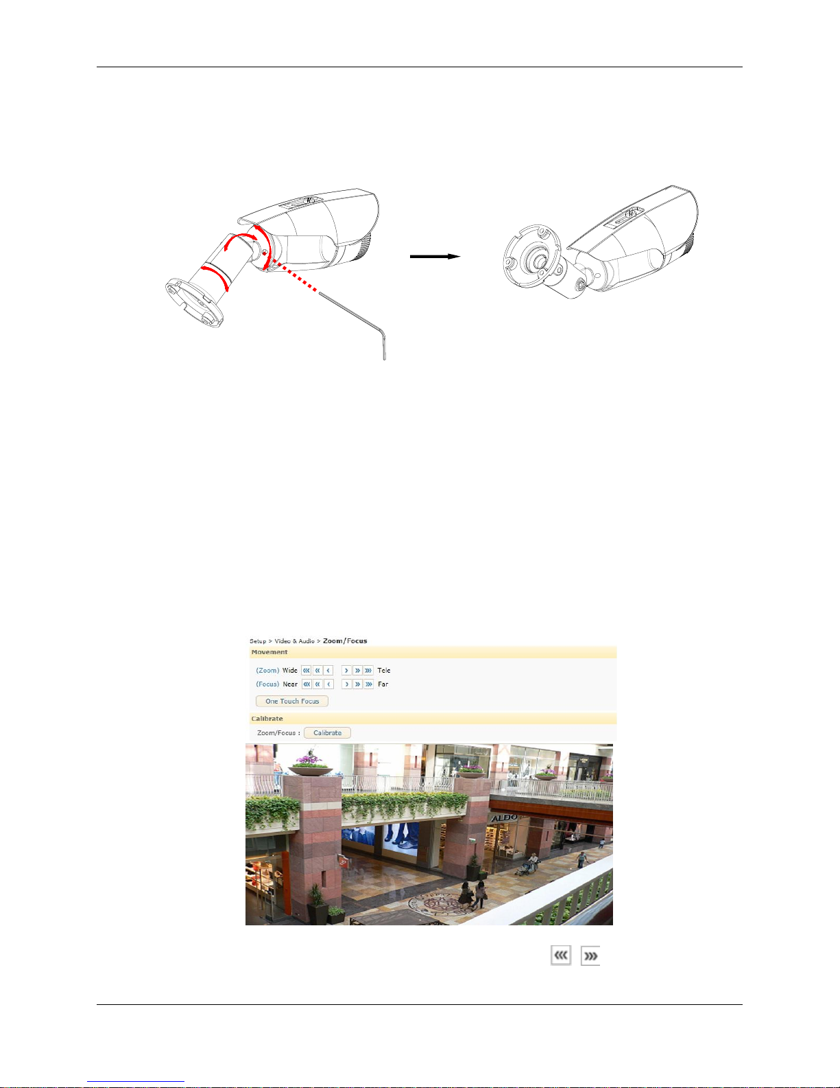
Installation
A. Loosen the joint(③) with the hex wrench driver, and
rotate the camera bracket 180 degrees if the bracket was
fixed for wall mount(image on the left).
Then, tighten the joint(③).
B. Loosen the joint(②) to ideally adjust the tilt angle of the
camera, and tighten it if the angle is appropriate.
C. Adjust the angle delicately if necessary after the
installation on the ceiling.
①
②
A. Loosen the joint(②) with the hex wrench driver to
adjust the tilt angle of the camera for wall mount.
B. Adjust the angle delicately by loosening the joint(①)
if necessary after the installation on the wall.
Model Shown: ADCi610-M022
Wall Mount
Ceiling Mount
Adjusting angle of the camera
Adjust the angle of the camera by changing the heading direction by reference to the following pictures
Adjusting zoom and focus IPL02B1BNWIY & IPL02B2BNWIY
Your camera is supported with motorized zoom and focus. Thus, connecting the device to a network is
pre-requisite to enable the adjustment of zoom and focus. For the network connection, refer to the
section, Network Connection and Configuration in this manual.
Once the device is on the network and the webpage is open, go to Setup> Video > Zoom/Focus.
Then, the features shown below will appear.
1. Adjust zoom and focus by clicking the arrow buttons. The buttons
move the lens more
9
Page 14
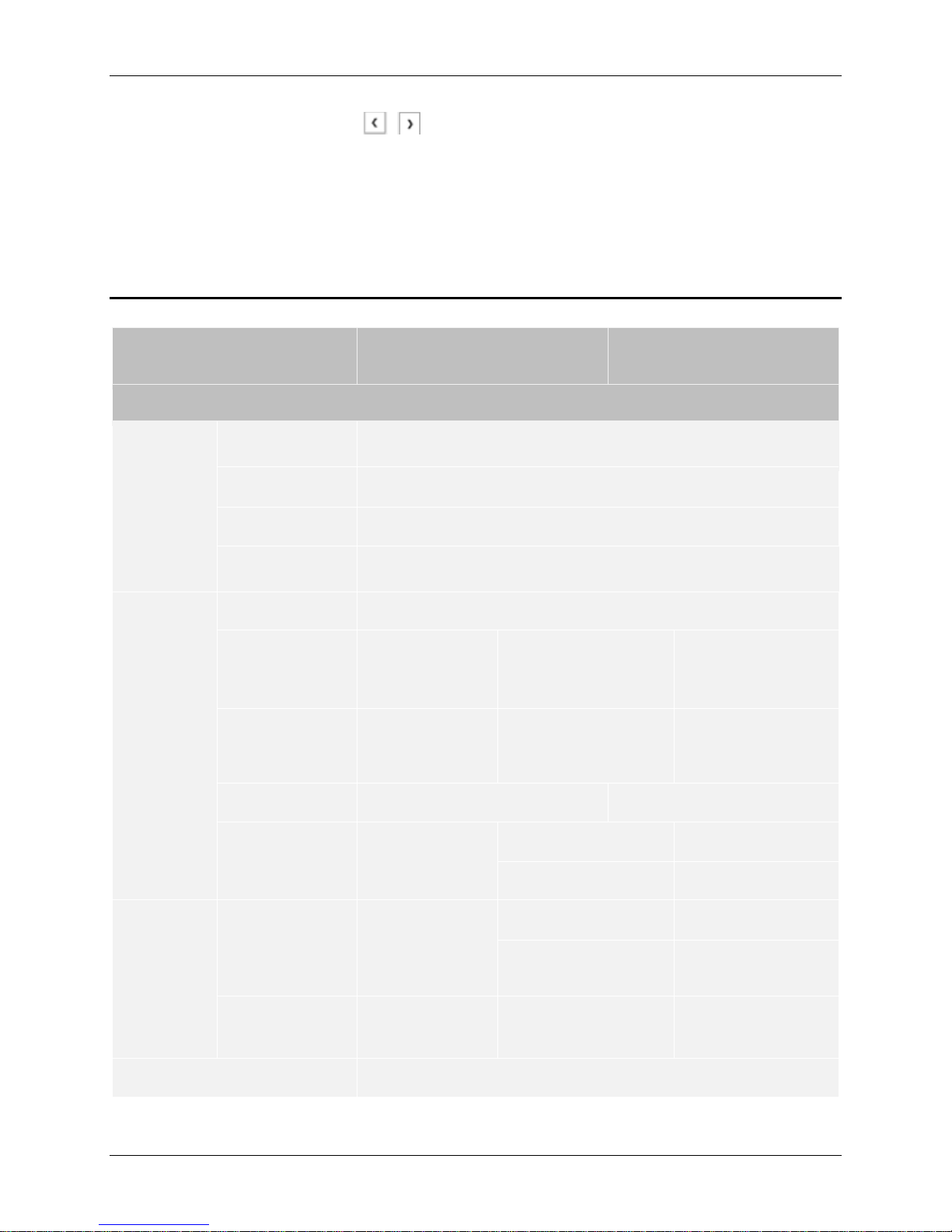
Specifications
Model List
ADCi610-M022
IPL02B1BNWIY
IPL02B2BNWIY
Camera
Image
Sensor
Max.
Resolution
1080p (1920x1080)
Pixel Size
3x3 ㎛
Type
CMOS
Active Image
Area
5,856 H x 3,276V ㎛
Lens
Type
Built-in Lens
Focal Length
4.3 mm
IPL02B2BNWIY
IPL02B1BNWIY
3.0(w) ~ 9.0(t) mm
2.8(w) ~ 12.0(t) mm
F No.
F2.0
F1.2(w) ~ F2.3(w),
Optical 3x Motorized
Focus & Zoom lens
F1.4
IRIS
Fixed
Auto iris
Format
1/2.9”
IPL02B2BNWIY
IPL02B1BNWIY
1/2.9”
1/2.7”
Angle of
View
Horizontal
74.4°
IPL02B2BNWIY
IPL02B1BNWIY
Approx. 110.8°(Wide)
to 35.5°(Tele)
Approx. 106°(Wide)
to 32°(Tele)
Vertical
40.8°
Approx. 57.7°(Wide)
to 19.9°(Tele)
Electronic Shutter Time
1/2~1/10,000 seconds
extensively than the buttons
Or, click One Touch Focus to automatically set the lens focus.
Refer to the camera’s Configuration Manual for more detailed configuration about zoom and focus on
the webpage.
.
Specifications
10 Quick Start Guide
Page 15

Specifications
Min. Illumination
Color : 1.0 Lux(30IRE)
B/W: 0 Lux(IR LED On)
Color : 0.5 Lux(30IRE)
B/W: 0 Lux(IR LED On)
CODEC
Video Compression
H.264 Baseline, Main, High profile(MPEG-4 Part 10/ AVC),
MJPEG(Motion JPEG)
Video Streaming
Dual Stream, Configurable streams in H.264, MJPEG
H.264: Controllable frame rate, bandwidth(VBR/CBR),GOP
MJPEG: Controllable frame rate, JPEG quality
Resolutions
1920x1080
1280x720
1120x630
960x540
800X450,
640X360
480x270
320x180
1920x1080
1280x720
1120x630
960x540
800X450,
640X360
480x270
320x180
Max Frame Rate
H.264: Max 30fps in all resolution
MJPEG: Max 30fps in all resolution
Special Features
Image Settings
Configurable brightness, contrast, saturation, sharpness
Orientation Control
Flip & Mirror
Rotation Control
None / Left(-90 degrees) / Right(+90 degrees)
Dynamic 2D Digital Noise
Reduction(DNR)
Supported (1 ~ 15)
Smart Bitrate Control
Supported (In VBR mode)
Exposure Adjustment
+1.0, +0.6, +0.3, 0, -0.3, -0.6, -1.0 EV
White Balance
ATW1 / ATW2 / Push / Manual
Back Light Compensation
None / Left(
90 degrees) / Right(+90
degrees)
IR Illuminator
Off / Manual
Wide Dynamic Range
On / Off
Flickerless Control
Normal, 50Hz, 60Hz
DSS (Sens-up)
2X ~ 16X, Off
11
Page 16
Specifications
Day & Night
Removable IR cut filter
OSD
Time stamp and text caption overlay
Privacy Zone
4 configurable regions (Configure with IE only)
Network
Ethernet Standard
10 / 100 / Base-T
QoS Layer 3 DiffServ, TCP/IP, UDP/IP, HTTP, HTTPS, FTP,
RTSP, RTCP, RTP/UDP, RTP/TCP, mDNS, UPnP™, SMTP,
DHCP, DNS, DynDNS, NTP, SNMPv1/v2c, IGMP, ICMP,
SSLv2/v3, TLSv1
Multi-level access with password protection
Once per 24 hours
Protocol
Security
NTP Time Synchronization
Poll Rate
Integration
Application Programming
Interface
Software Development Kit(SDK) IAPI3
ONVIF 2.4 Profile S (or later)
Event Sources
Video Motion Detection; Sensor(DI)
Event Actions
File upload: E-mail, FTP,
Notification: E-mail, FTP, HTTP, TCP
Record : SD card storage, FTP
Trigger-Alarm(DO)
Event Metadata Streaming
(RTSP/RTP)
Video Motion Detection(MD)
Mechanical
Material
Aluminum Die-Casting
Weight
600g (1.32 lbs)
870g (1.92lbs)
Dimension
2.9” x 3.0” x 4.13”
3.5” x 3.4” x 11”
Protection Class
IP66, weather-proof
Environment
Operating Humidity
Humidity up to 85% RH (non-condensing)
Operation Temperature
[DC12V] -20°C ~ 50°C (-4°F ~ 122°F)
[PoE] -20°C ~ 50°C (-4°F ~ 122°F)
Storage Temperature
-40°C ~ 60°C (-40°F ~ 140
°F)
12 Quick Start Guide
Page 17
Specifications
Power
Power Source / Consumption
DC 12V, PoE IEEE 802.3af
Class 2 / max. 6W
DC 12V, PoE IEEE 802.3af
Class 2 / max.
12W@DC12V
Tolerance (Voltage Variation)
± 10% (DC10.8V ~ 13.2V)
Interface
Edge Storage
1x mircoSD/microSDHC/microSDXC memory card slot
(card not included)
64GB Capacity
Regulatory
Safety
UL60950-1
IEC 60950-1
CSA 22.2 No. 60950
EN60950-1
Emission
FCC Part 15 Class A
EN55022 Class A
AS/NZS CISPR 22 Class A
ICES-003/NMB-003 Class A
Immunity
EN50130-4
EN55024
EN61000-6-1
IEC 62599-2
RoHS/WEEE
Environment
13
Page 18
Network Connection and Configuration
Network Connection and Configuration
Network Connection Types
There are many different ways that you can connect the camera to your network, depending on your
applications requirements. You should always set the camera’s network settings according to your
network configurations. The following diagrams depict some typical applications with guidelines on
network settings. For more information on network settings, always consult with your network
administrator or ISP as required.
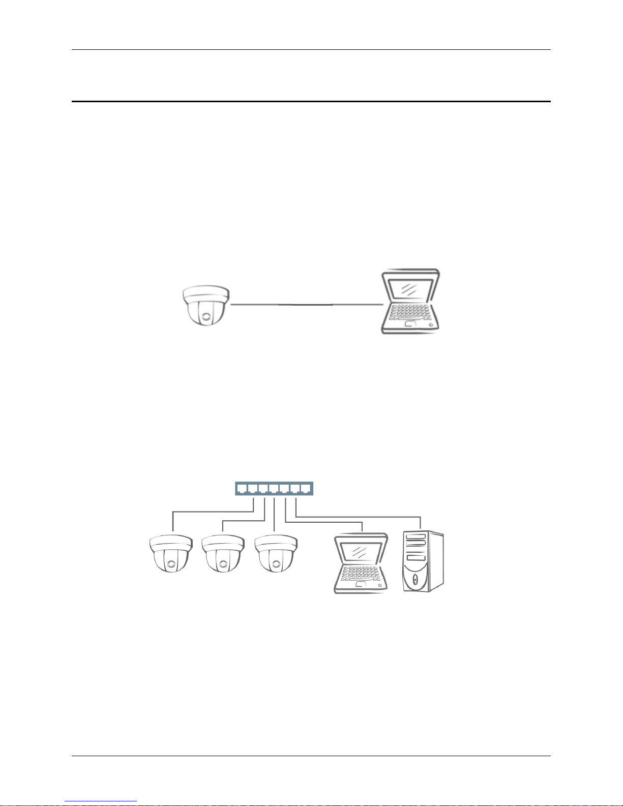
Type 1: Direct Connection to a PC
Connect the camera directly to a PC using a standard Ethernet cable connected to a LAN connector.
To access the camera, the PC must be on the same network as the camera. The default IP address of
the camera is a static one (e.g. 192.168.1.168) with the subnet mask, 255.255.255.0. If the default
static IP address cannot be used on your network, use Illustra Connect to reassign an IP address to
your camera, or reassign the IP address of your PC to be on the same network as the camera. Then,
you can access the camera from your PC.
Type 2: Connecting Camera(s) to a Local Area Network (LAN)
To add the camera(s) to an existing LAN, just connect the camera(s) to the hub or switch on your
network.
Your camera has DHCP enabled as a default, so IP address is supposed to be assigned by a DHCP
server. However, if you do not have a DHCP server on your network or if your DHCP server fails to
assign an IP address, the IP address of your camera will default to 192.168.1.168 with the subnet mask,
255.255.255.0. Use Illustra Connect to reassign an IP address to your camera if the IP address is not
on the same network as your PC.
14 Quick Start Guide
Page 19
Network Connection and Configuration
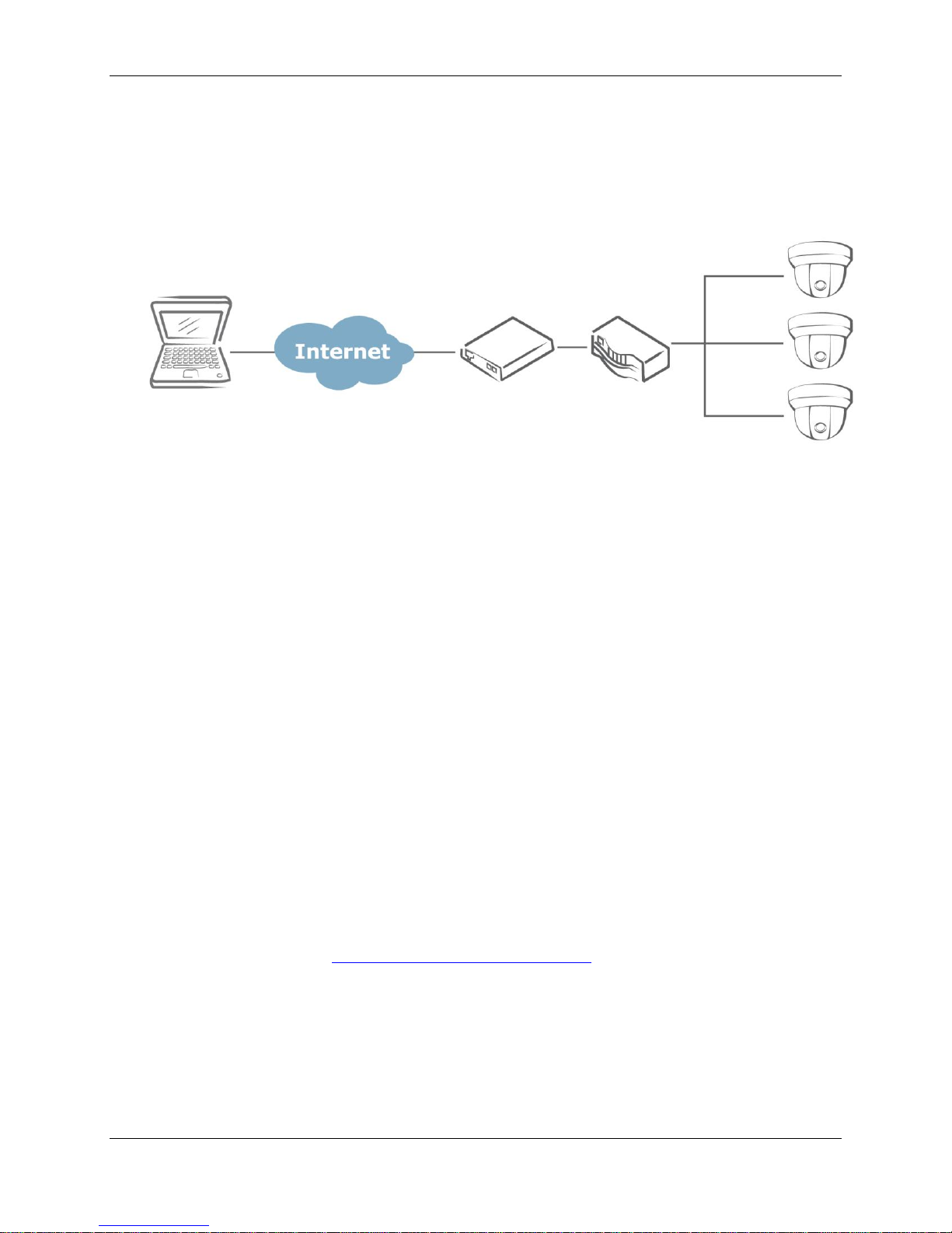
Type 3: Remote Connection via the Internet
If the network where the camera resides is connected to the Internet, you can also provide remote
access to your camera over the Internet.
Typically a broadband router has built-in DHCP function to assign a local IP address to your camera.
You can alternatively assign a fixed IP address to the camera to prevent it from frequent changing.
To access the camera from a local PC, simply use the local IP address of the camera.
To enable remote access, you must configure your router/firewall to forward an incoming request to
that fixed local IP address of the camera. Therefore, when an external host sends a request to access
your camera, the request will first reach the router’s external IP address and then be forwarded to the
local IP address of the camera.
Port forwarding is based on the service you want to provide. For example, forward HTTP port to enable
remote web access to your camera, or RTSP port to enable access to video/audio streams from the
camera.
Accessing the Camera for the First Time
The camera comes with a web-based setup utility, allowing you to view the video of the camera and
configure the camera for optimal use in your environment.
To access the camera’s web-based control utility, you need a PC that meets the following
requirements:
Operating System: Windows Vista or Windows 7, Windows 8 and Mac OS
Browser: Internet Explorer Version 8.0 or later, Chrome, Safari and Firefox
CPU: Intel Core 2 duo P8400 or higher
VGA: DirectX 3D supported (*If Direct3D Acceleration is disabled, type ‘dxdiag’ from
Start >Run on your computer, and check the DirectX Features.)
RAM: DDR3 4GB or more
Others: Java (http://java.com/en/download/index.jsp) + QuickTime
Then, take the following steps to connect your PC to the camera.
Step 1: Make the connection
For initial setup purpose, connect one end of an Ethernet cable to the RJ45 connector of the camera
and the other end to the LAN port on your PC.
Step 2: Configure your PC’s IP address
Configure the IP address of your PC referring to Network Connection Types on page 4.
15
Page 20
Network Connection and Configuration
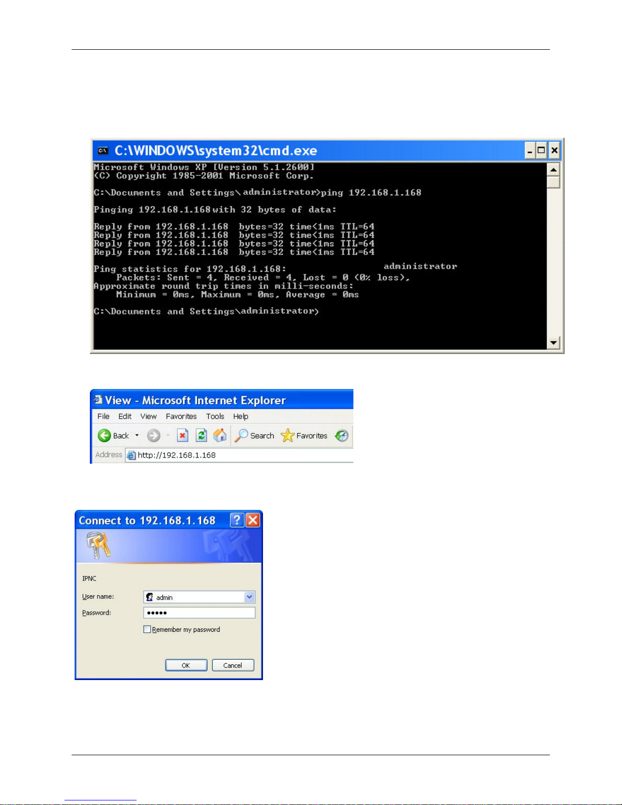
Step 3: Verify the connection between the PC and the IP Cam
1. Launch Command Prompt by clicking the Start menu, Programs, Accessories and then
Command Prompt.
2. At the prompt window, type ping x.x.x.x, where x.x.x.x is the IP address of the camera.
3. If the message of “Reply from…” appears, it means the connection is established.
Step 4: Access the camera from IE browser
Open the IE browser and enter the IP address of the camera in the URL field.
When user clicks on “Setup” or other menu items, then camera prompts the user for credentials and
screenshot is different from IE: When prompted to login, enter the user name and the password. (The
defaults: admin, admin). Note that the password is case-sensitive.
16 Quick Start Guide
Page 21

Network Connection and Configuration
Using the Illustra Connect Tool to Manage Cameras
In addition to using the IE browser to access your camera, you can alternatively use the provided tool,
Illustra Connect.
Illustra Connect is a management tool designed to manage your network cameras on the LAN. It can:
- help you find multiple network cameras.
- set IP addresses automatically resolving conflicts.
- show connection status.
- manage firmware upgrade.
17
Page 22
Using exacqVision Edge
Using exacqVision Edge
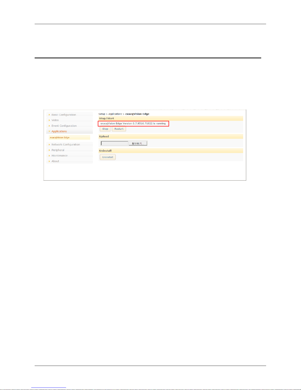
Features to install and manage exacqVision Edge server software on the camera are found in Setup >
Applications > exacqVision Edge on the camera’s web interface. The page will allow the installation or
removal of Edge or if the software is installed, starting or stopping the server. exacqVision Edge cannot
be run without a SD Card installed in the camera. If the Edge and a SD Card are present and Edge will
not start, try removing and reinserting the SD Card or formatting the card from the Storage menu found
at the top of the web interface.
If you need the instructions on running and updating of the exacqVision Edge application via the
camera’s webpage, refer to the camera’s Configuration Manual for the details.
18 Quick Start Guide
 Loading...