

Page 1
Illustra Flex 3MP Indoor and Outdoor Dome Cameras
Quick Start Guide
Page 2

Notice
Please read this manual thoroughly and save it for future use before attempting to connect or operate
this unit.
The information in this manual was current when published. The manufacturer reserves the right to
revise and improve its products. All specifications are therefore subject to change without notice.
Copyright
Under copyright laws, the contents of this manual may not be copied, photocopied, reproduced,
translated or reduced to any electronic medium or machine-readable form, in whole or in part, without
prior written consent of Tyco Security Products.
© 2017 Tyco Security Products. All rights reserved.
Tyco Security Products
6600 Congress Avenue
Boca Raton, FL 33487 U.S.A.
Customer Service
Thank you for using American Dynamics products. We support our products through an extensive
worldwide network of dealers. The dealer through whom you originally purchased this product is your
point of contact if you need service or support. Our dealers are empowered to provide the very best in
customer service and support. Dealers should contact American Dynamics at (800) 507-6268 or
(561) 912-6259 or on the Web at www.americandynamics.net.
Trademarks
The trademarks, logos, and service marks displayed on this document are registered in the United
States [or other countries]. Any misuse of the trademarks is strictly prohibited and Tyco Security
Products will aggressively enforce its intellectual property rights to the fullest extent of the law,
including pursuit of criminal prosecution wherever necessary. All trademarks not owned by Tyco
Security Products are the property of their respective owners, and are used with permission or
allowed under applicable laws.
Product offerings and specifications are subject to change without notice. Actual products may vary
from photos. Not all products include all features. Availability varies by region; contact your sales
representative.
Page 3

Table of Contents
Illustra Flex Series 3MP Indoor Dome Camera 1
Product features 1
Product overview 1
Installation 5
Illustra Flex Series 3MP Outdoor Dome Camera 9
Product features 9
Product overview 9
Installation 13
System Requirements 18
Network Connection 19
Default IP Addr ess 19
DHCP 20
Managing cameras with the Illustra Connect tool 21
Network Topology 23
Appendix A: Technical Specifications 24
Page 4
Warning
• These units operate at AC 24V/ PoE.
• Installation and service should be performed only by qualified and experienced technicians
and comply with all local codes and rules to maintain your warranty.
• To reduce the risk of fire or electric shock, do not expose the product to rain or moisture.
• Wipe the camera with a dry soft cloth. For tough stains, slightly apply with diluted neutral
detergent and wipe with a dry soft cloth.
• Do not apply benzene or thinner to the camera, which may cause the surface of the unit to
be melted or lens to be fogged.
• Avoid aligning the lens to very bright objects (for example, light fixtures) for long periods of
time.
• ITE is to be connected only to PoE networks without routing to the outside plant.
• The power supply shall be approved for ITE NEC Class 2 or LPS with a rating of 24VAC,
550mA minimum and 50 degrees Celsius.
• Video Out connection should be intra-building only.
• Avoid operating or storing the unit in the following locations:
• Extremely humid, dusty, or hot/cold environments. Recommended operating
temperature is:
• Indoor Minidome: -20˚C to 50˚C (-4˚F to 122˚F)
• Outdoor Minidome: -50˚C to 50˚C (-58˚F to 122˚F)
• Power over Ethernet (PoE) does not support heater.
• Near sources of powerful radio or TV transmitters.
• Near fluorescent lamps or objects with reflections.
• Under unstable or flickering light sources.
WEEE (Waste Electrical and Electronic Equipment). Correct disposal of this product (applicable
in the European Union and other European countries with separate collection systems). This
product should be disposed of, at the end of its useful life, as per applicable local laws, regulations,
and procedures.
Page 5
Illustra Flex 3MP Indoor and Outdoor Dome Cameras Quick Start Guide
Illustra Flex Series 3MP Indoor Dome Camera
This chapter provides product features, installation procedures, and connection information regarding
the Illustra Flex Series 3MP Indoor Dome camera.
Product features
Len cases require special care when handling and cleaning to avoid scratches. For information on
bubble handling and cleaning, see 8200-1174-01 Bubble Clearing Procedure Application Note.
Go to https://illustracameras.com/products.
From the Products page, select your camera product range and then select your camera model. Click
Downloads and search for Bubble Handling and Cleaning Procedure.
Product overview
This chapter explains the features and installation of the Flex Indoor Dome camera. Product code
and description of the camera is provided in the table below.
Table 1 Product code and description of the Flex Indoor Dome camera
Product Code Description
IFS03D1ICWTT Illustra Flex 3MP Mini-dome, 2.8-12mm, indoor, vandal, clear, white, TDN, TWDR
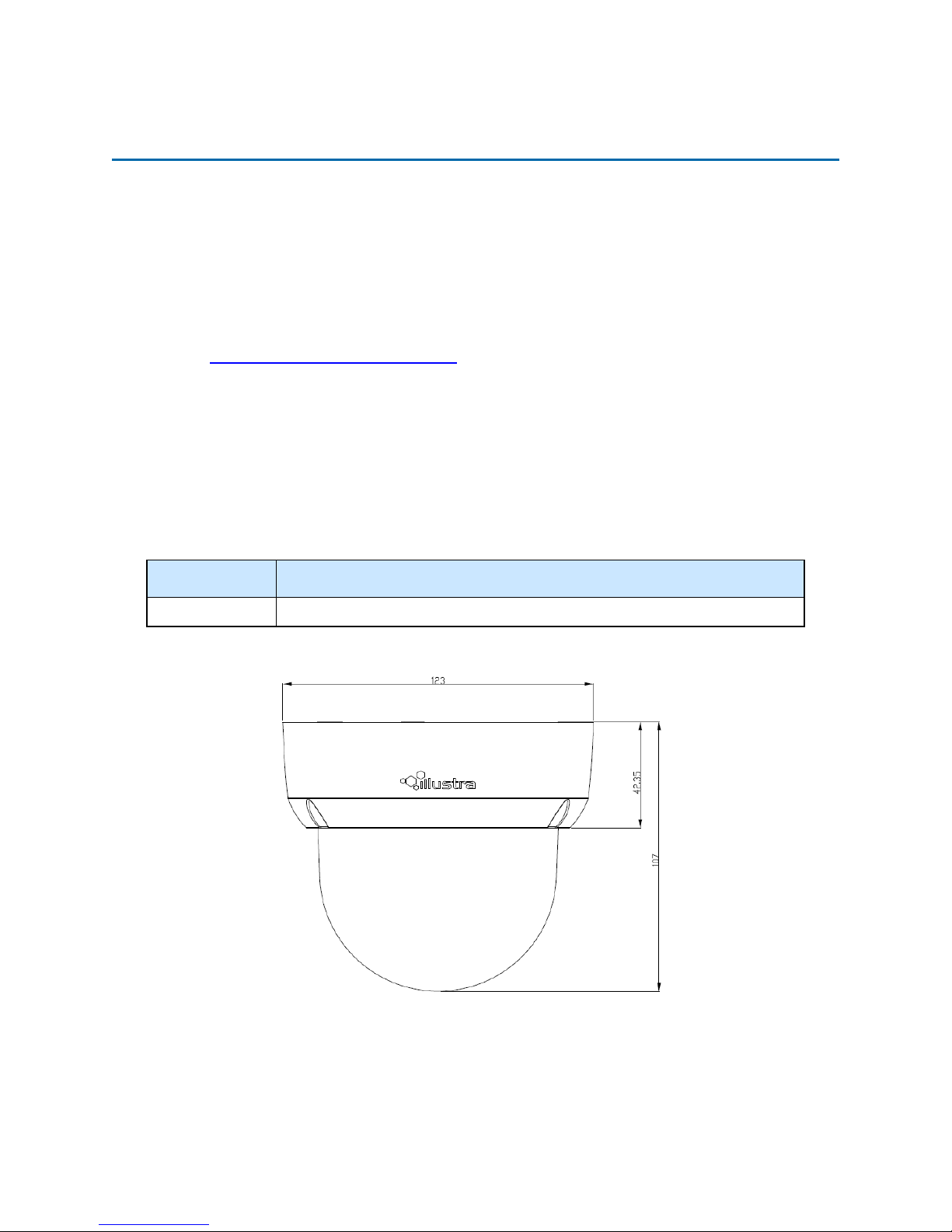
Figure 2 Physical dimensions of the Indoor Dome camera (mm)
1 8200-1456-02 E0
Page 6
Illustra Flex 3MP Indoor and Outdoor Dome Cameras Quick Start Guide
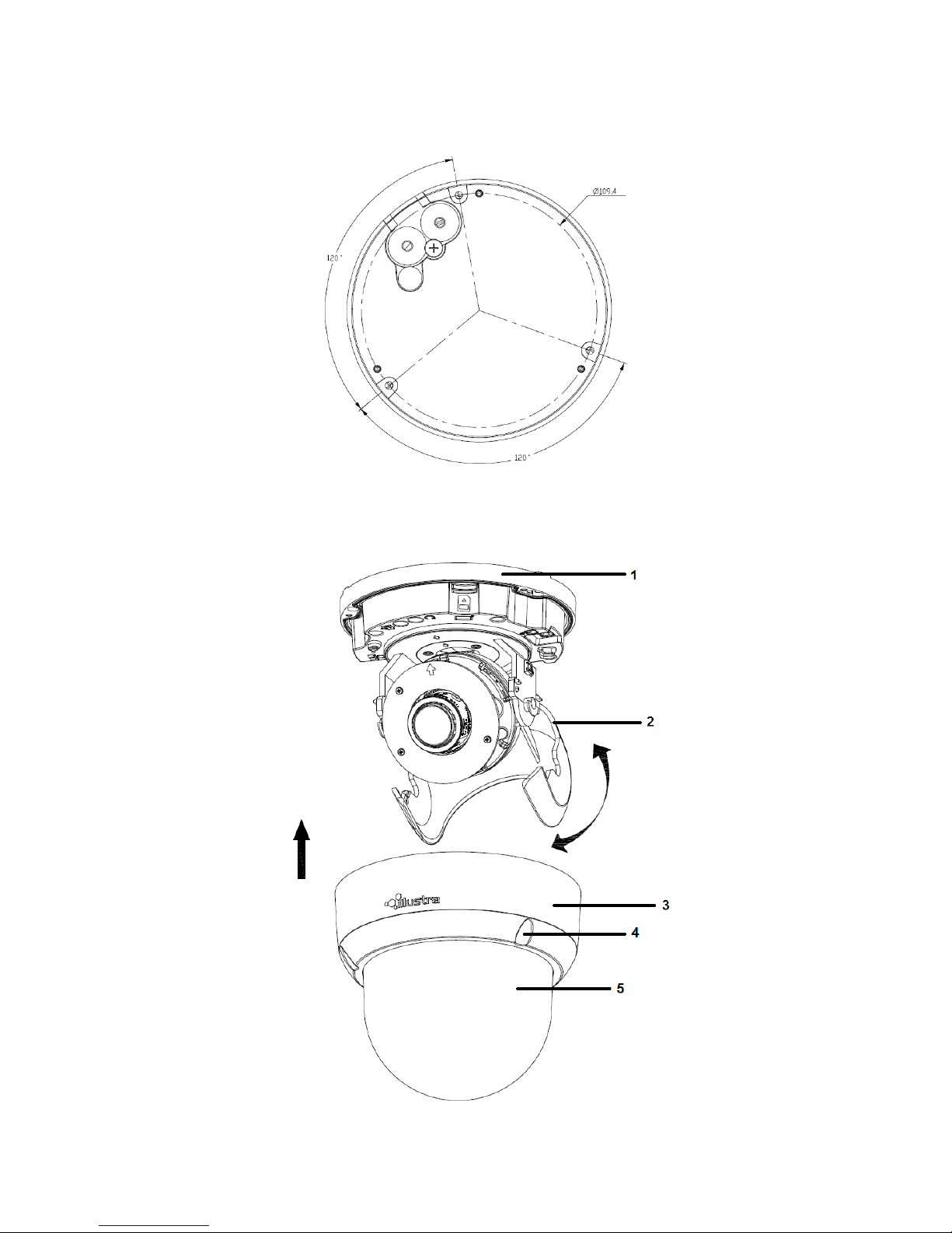
Figure 3 Physical dimensions of the Indoor Dome camera
Figure 4 Pictorial index of the camera
8200-1456-02 E0 2
Page 7
Illustra Flex 3MP Indoor and Outdoor Dome Cameras Quick Start Guide
Table 5 Pictorial index descriptions
Index number Description
1 Camera bottom case
2 Tilt adjustment bracket
3 Loosen the screw to take off camera housing
4 Camera housing
5 Dome cover
Figure 6 Pin definitions of the unit
3 8200-1456-02 E0
Page 8
Illustra Flex 3MP Indoor and Outdoor Dome Cameras Quick Start Guide
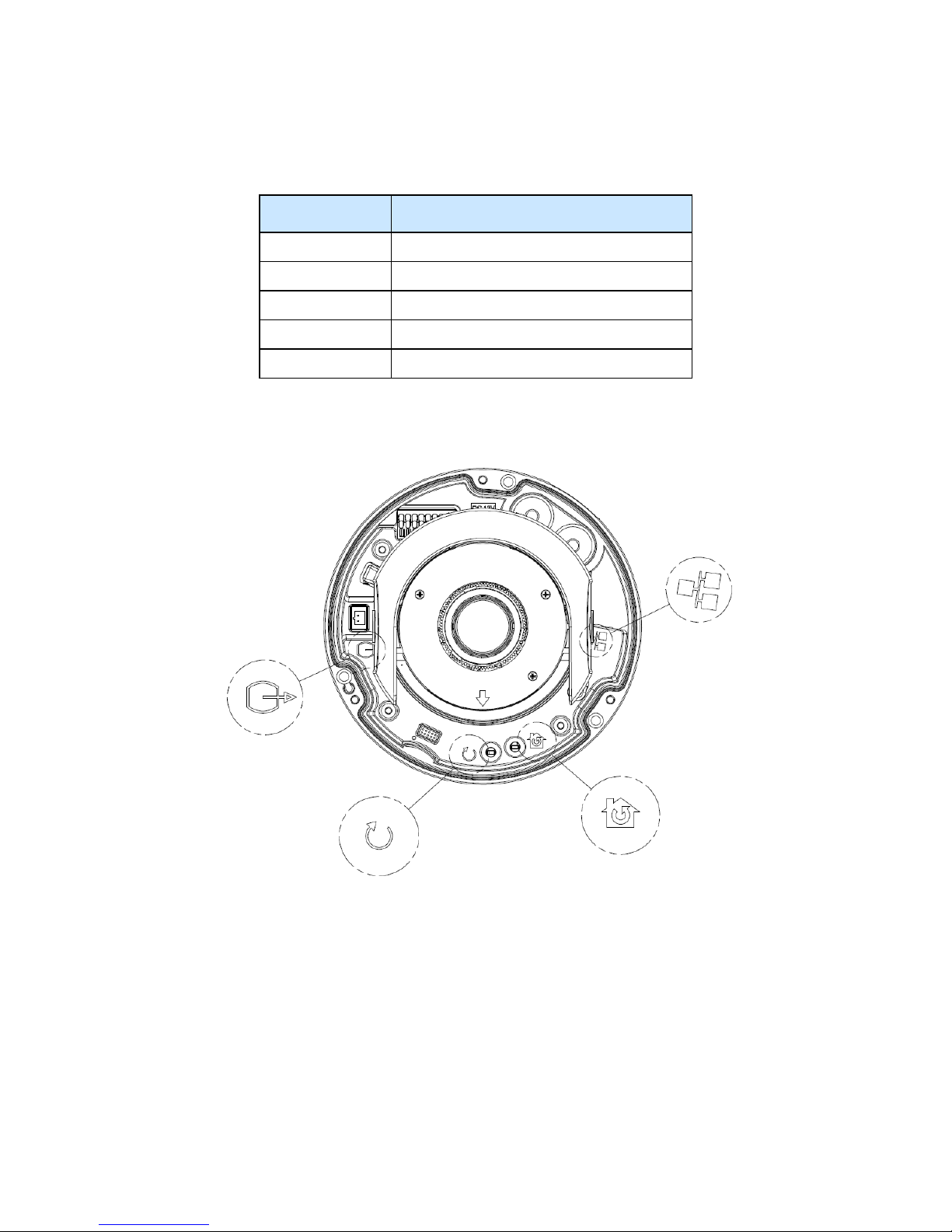
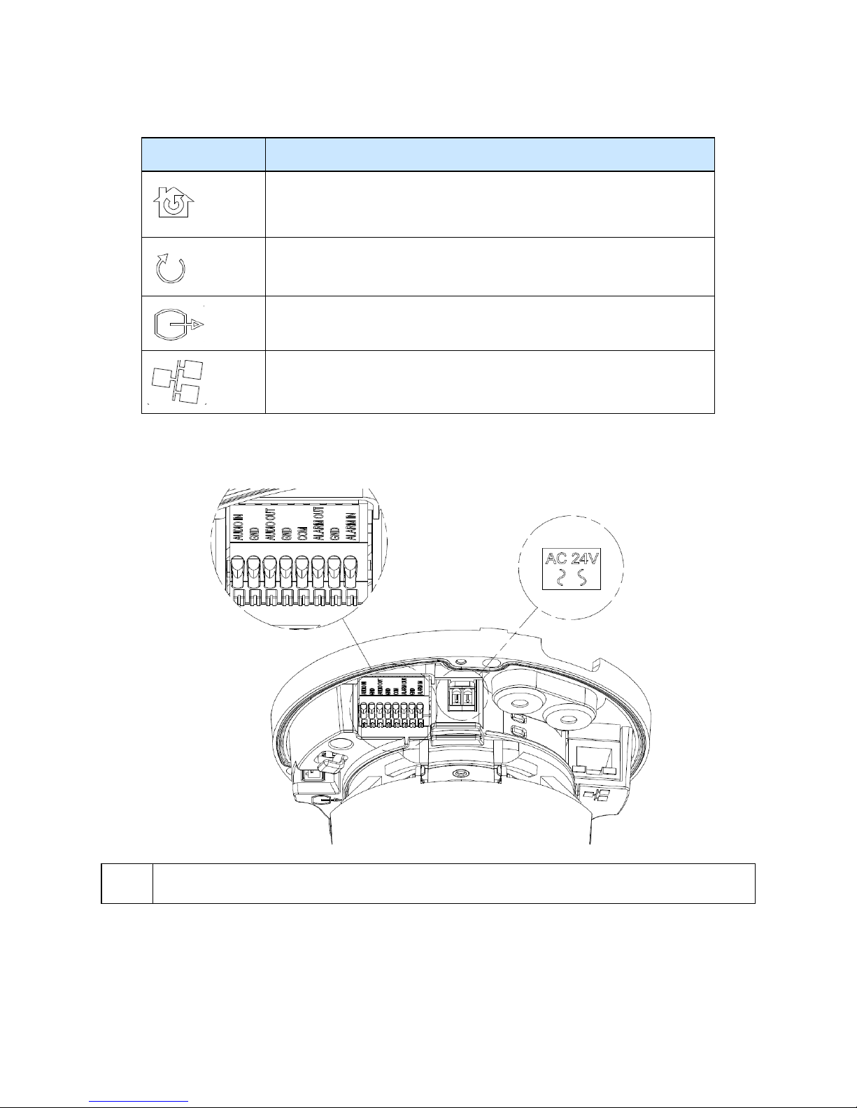
Table 7 Interior button descriptions
Interior button Description
Resets to factory default by pressing and holding the button for five seconds.
Reboots the unit.
Analog out port.
Power over Ethernet (PoE) port.
Figure 8 Connectors of the camera
NOTE
Connectors and field wiring terminals for external Class 2 circuits provided with marking indicating
minimum Class of wiring to be used. Class 2 shall be marked adjacent to the field wiring terminals.
8200-1456-02 E0 4
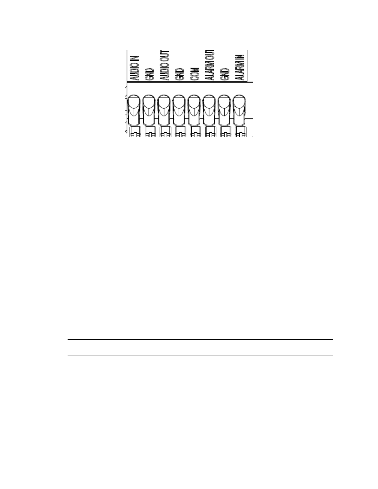
Figure 9 Audio and alarm pin definitions
Page 9
Installation
In the box
Illustra Flex 3MP Indoor and Outdoor Dome Cameras Quick Start Guide
Check everything in the packing box matches to the order form and the packing slip. In addition to
this guide, items below are included in the packing box:
• 1 Network Indoor Dome Camera
• 1 printed Quick Start Guide
• 1 printed Regulatory document
• 1 NTSC/PAL output female BNC cable
• 1 adapter plate (for pendant cap
• 3 7mm adapter plate screws
• 1 Torx 10 Security L-Key
• 3 18mm plastic anchors and screws
• 1 installation template sticker
• 2 8mm pendant cap screws
Contact your dealer if any item is missing.
Note:The adapter plate is for an installation with a ADCi6DPCAPI (W/B) pendant cap and can also
be used to mount to a standard dual gang electrical box.
Installation tools
The following tools assist with installation:
• a drill
• screwdrivers
• wire cutters
5 8200-1456-02 E0
Page 10
Illustra Flex 3MP Indoor and Outdoor Dome Cameras Quick Start Guide
Checking appearance
When first unboxing, check whether if there is any visible damage to the appearance of the unit and
its accessories. The protective materials used for the packaging should be able to protect the unit
from most types of accidents during transportation.
Remove the protective part of the unit when every item is checked in accordance with the list in In
the box on page 5.
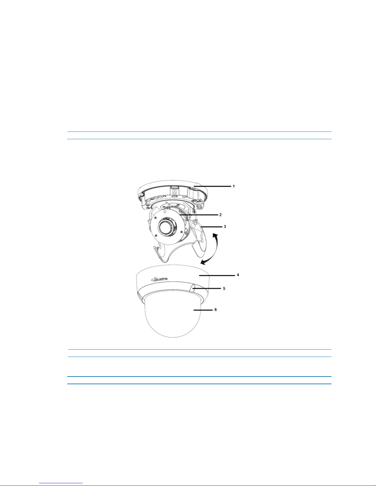
Procedure 1 Disassembling the camera
Refer to Figure 10 on page 6 for a pictorial index of disassembling the camera.
Step Action
1 Remove the screws (5) to take off camera housing.
2 Gently remove the camera housing (4) and dome cover (6) and set aside.
Figure 10 Disassembling the camera
Procedure 2 Connecting the wires
Step Action
This unit supports one of the following options as power supply:
1 AC 24V:
a Connect 24V (~ ) cables to terminals ~ AC 24V
2 PoE:
8200-1456-02 E0 6
- End -
Page 11
Illustra Flex 3MP Indoor and Outdoor Dome Cameras Quick Start Guide
a Connect the RJ-45 jack to a PoE compatible network device that supplied power
through the Ethernet cable.
3 Insert Audio cable and alarm cable to the unit, and connect the network cable to the RJ-45
terminal of a switch.
Note:The power source needs to be NEC Class 2 or LPS. The PoE connection should be provided
by a UL Listed product and the connections shall be made in accordance with Article 800 of the NEC
or local regulations.
- End -
Procedure 3 Mounting the camera
Step Action
1 Mark holes that correspond to the camera base on the mounting surface
2 Drill holes.
3 Fasten the anchors to the mounting surface with screws.
4 Connect the Safety Wire (fall prevention wire, not supplied) with one end to the ceiling and
the other to the safety-cord screw of the unit.
5 Secure the unit bottom case to the wall or ceiling with tapping screws.
6 Adjust the viewing angle. Refer to Adjusting the Position on page 7 for information regarding
WARNING
CAUTION
Procedure 4 Adjusting the Position
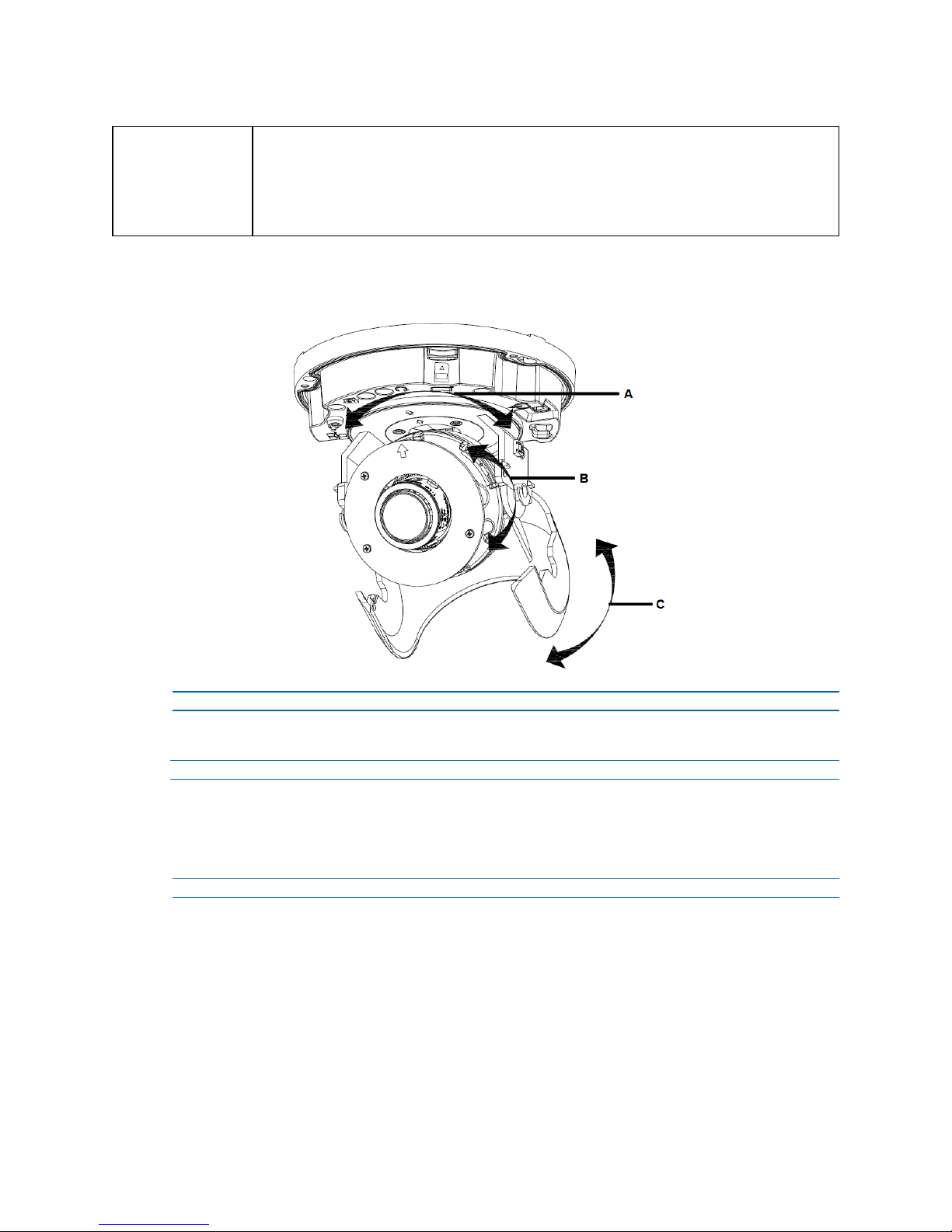
The unit has three axes for positioning, refer to Figure 11 on page 8. While monitoring, adjust the
position as below:
Step Action
1 Pan Adjustment (A). For Wall Mount and Tilted Ceilings
2 Horizontal Rotation (B)
how to adjust the viewing angle.
Depending on the material of your mounting surface, you may require different screws and
anchors than those as supplied. To prevent the unit from falling off, ensure that it is secured to a
firm place (ceiling slab or channel) with a safety wire (not supplied) strong enough to sustain the
total weight of the unit. Pay attention to the finishing at the end of the wire. Never turn the lens
more than 360°, which should disconnect or break internal cables.
Safety wire must be connected with one end to the ceiling and the other to the safety-cord screw of
the unit.
- End -
a Rotate the lens base (maximum 375°) until you are satisfied with the field of view.
a Rotate 3D assembly in the base. Do not turn assembly more than 360° as this
assembly may cause the internal cables to twist and disconnect or break.
3 Tilt Adjustment (C):
a Tilt the lens base (maximum 90°) until you are satisfied with the field of view.
7 8200-1456-02 E0
Page 12
Illustra Flex 3MP Indoor and Outdoor Dome Cameras Quick Start Guide
Limitation for three axes position:
CAUTION
• Pan range: 375°
• Tilt range: 90°
• Rotate range: Motorize Lens 356°
Figure 11 Adjusting the position of the camera
- End -
Procedure 5 Locking the Camera
Step Action
1 Use a soft, lint-free cloth to wipe the dome cover and remove fingerprints.
2 Attach the inner liner and camera housing.
3 Turn the power on after you have install the unit.
- End -
8200-1456-02 E0 8
Page 13
Illustra Flex 3MP Indoor and Outdoor Dome Cameras Quick Start Guide
Illustra Flex Series 3MP Outdoor Dome Camera
This chapter provides product features, installation procedures, and connection information regarding
the Illustra Flex Series 3MP Outdoor Dome camera.
Product features
Len cases require special care when handling and cleaning to avoid scratches. For information on
bubble handling and cleaning, see 8200-1174-01 Bubble Clearing Procedure Application Note.
Go to https://illustracameras.com/products.
From the Products page, select your camera product range and then select your camera model. Click
Downloads and search for Bubble Handling and Cleaning Procedure.
Product overview
This chapter explains the features and installation of the Flex Outdoor Dome camera. Product code
and description of the camera is provided in the table below.
Table 12 Product code and description of the Flex Outdoor camera
Product Code Description
IFS03D1OCWIT Illustra Flex 3MP Mini-dome, 2.8-12mm, outdoor, vandal, clear, white, TDN w/IR, TWDR
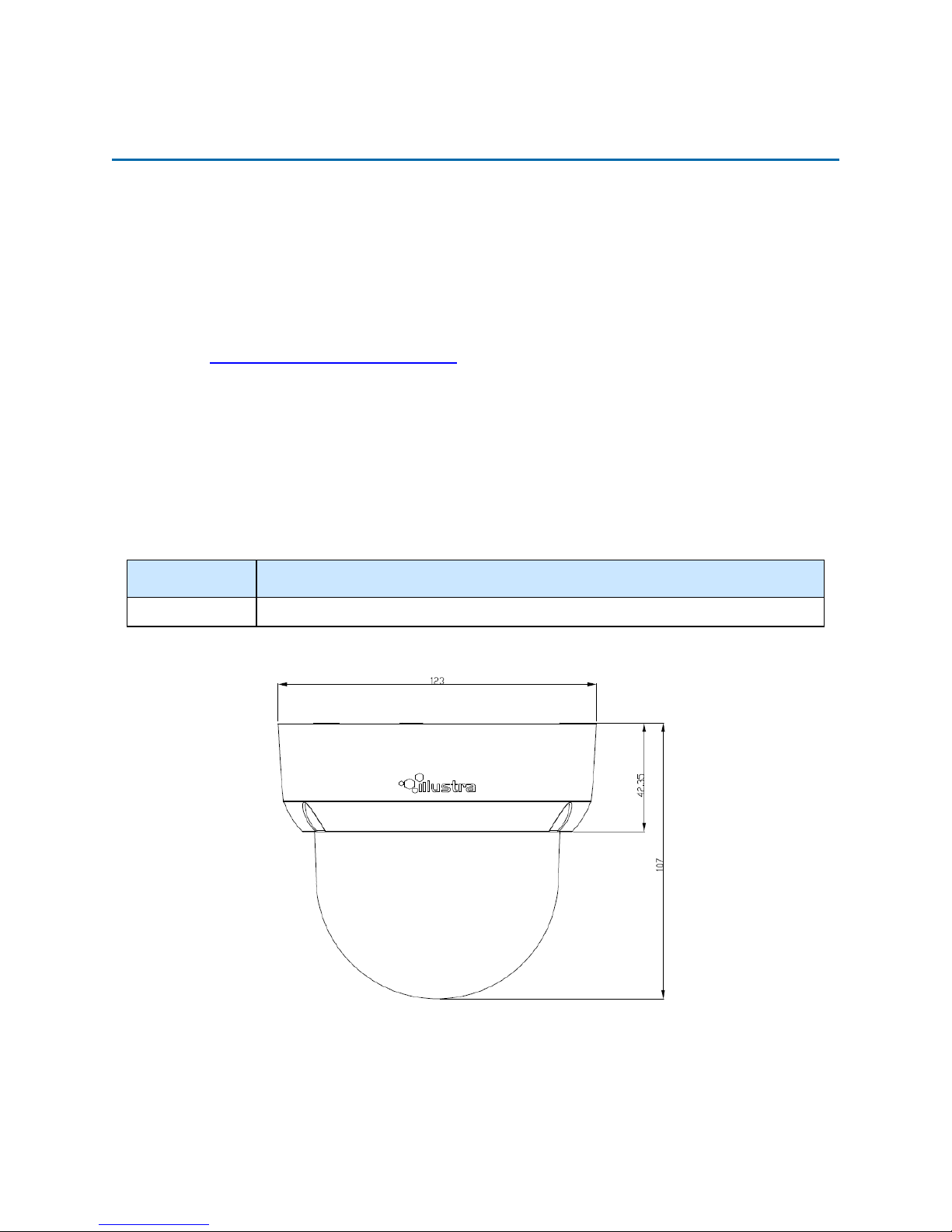
Figure 13 Physical dimensions of the Outdoor Dome camera (mm)
9 8200-1456-02 E0
Page 14
Illustra Flex 3MP Indoor and Outdoor Dome Cameras Quick Start Guide
Figure 14 Physical dimensions of the Outdoor Dome camera
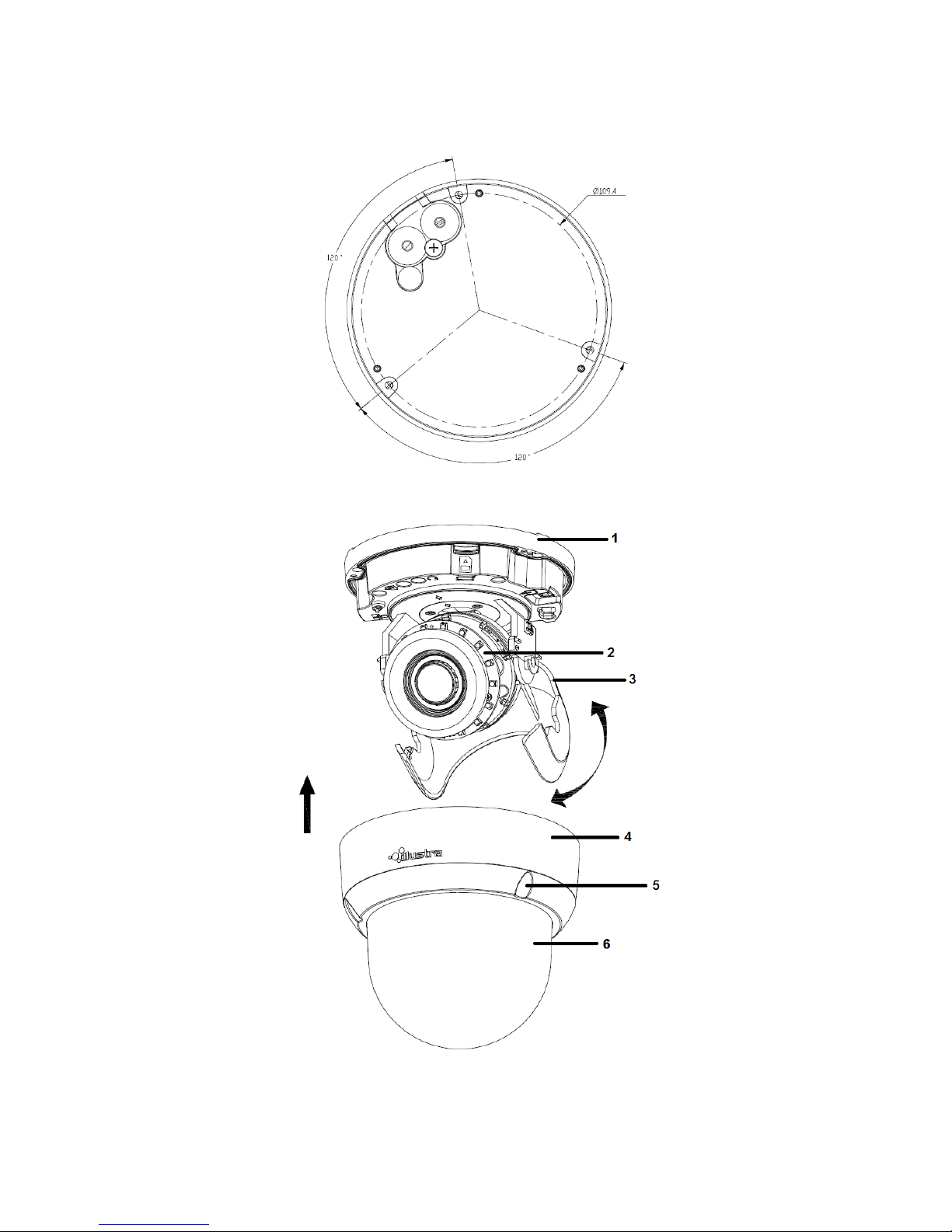
Figure 15 Pictorial index of the Outdoor Dome camera
8200-1456-02 E0 10
Page 15
Illustra Flex 3MP Indoor and Outdoor Dome Cameras Quick Start Guide
Table 16 Pictorial index descriptions
Index number Description
1 Camera bottom case
2 IR board
3 Tilt adjustment bracket
4 Camera top case
5 Loosen the screw to take off camera housing
6 Dome cover
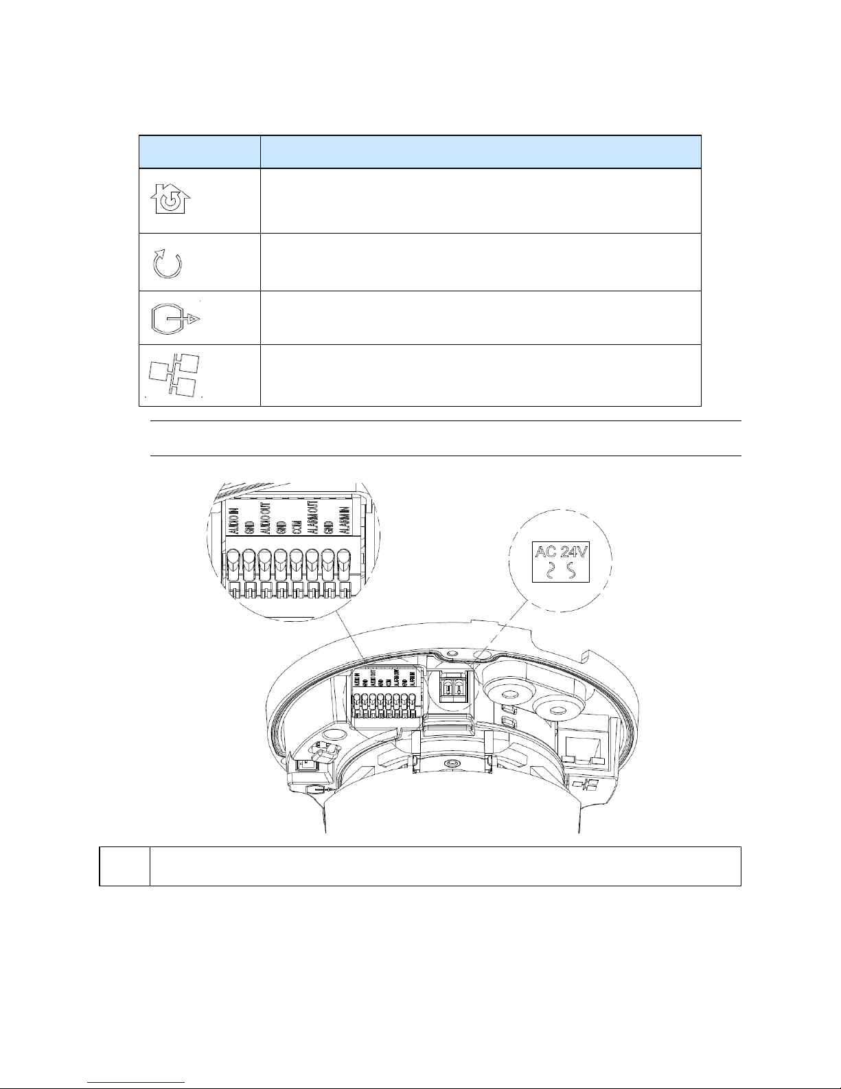
Figure 17 Pin definitions of the unit
11 8200-1456-02 E0
Page 16
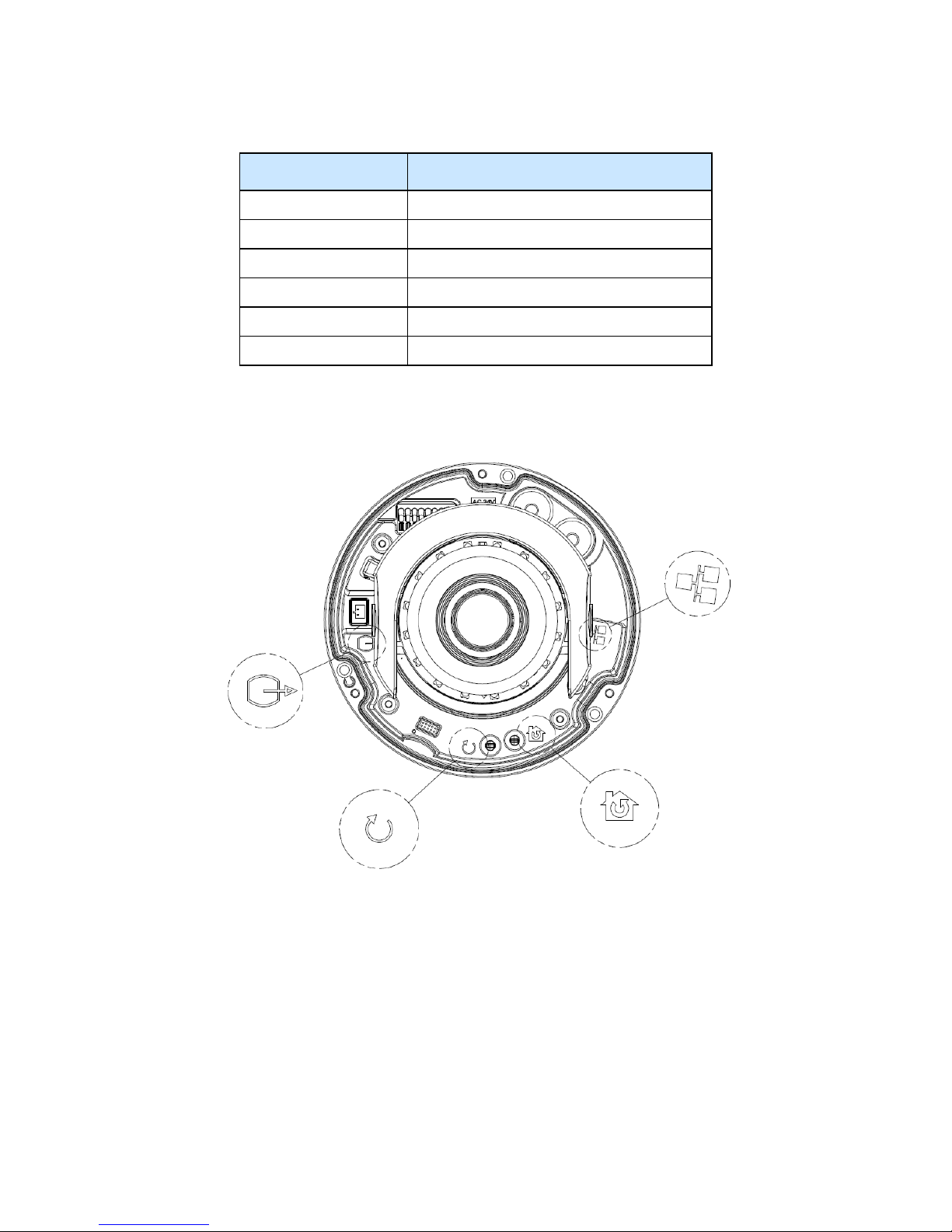
Illustra Flex 3MP Indoor and Outdoor Dome Cameras Quick Start Guide
Table 18 Interior button descriptions
Interior button Description
Resets to factory default by pressing and holding the button for five seconds.
Reboots the unit.
Analog out port.
Power over Ethernet (PoE) port.
Note:The connector cable of the Outdoor Dome Camera should be contained in a conduit suitable for
outdoor use.
NOTE
Figure 19 Connectors of the unit
Connectors and field wiring terminals for external Class 2 circuits provided with marking indicating
minimum Class of wiring to be used. Class 2 shall be marked adjacent to the field wiring terminals.
8200-1456-02 E0 12
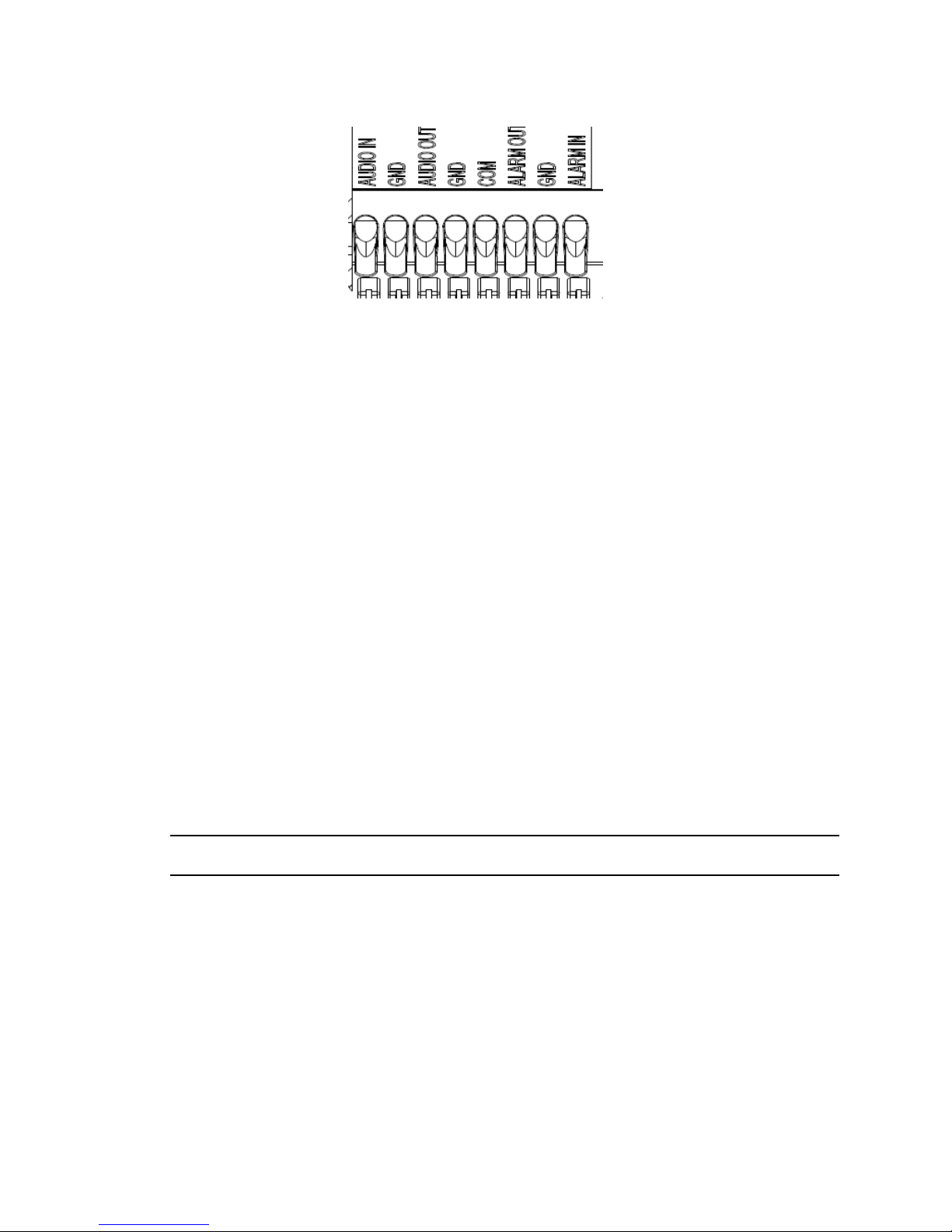
Figure 20 Audio and alarm pin definitions
Page 17
Installation
In the box
Check everything in the packing box matches to the order form and the packing slip. In addition to
this guide, items below are included in the packing box.
Illustra Flex 3MP Indoor and Outdoor Dome Cameras Quick Start Guide
• 1 Network Outdoor Dome Camera
• 1 printed Quick Start Guide
• 1 printed Regulatory document
• 1 NTSC/PAL output female BNC cable
• 1 adapter plate (for pendant cap)
• 3 7mm adapter plate screws
• Desiccant
• 1 Torx 10 Security L-Key
• 3 18mm plastic anchors and screws
• 1 installation template sticker
• 2 8mm pendant cap screws
Contact your dealer if any item is missing.
Note:The adapter plate is for an installation with a ADCi6DPCAPI (W/B) pendant cap and can also
be used to mount to a standard dual gang electrical box.
Installation tools
The following tools assist with installation:
• a drill
• screwdrivers
• wire cutters
13 8200-1456-02 E0
Page 18
Illustra Flex 3MP Indoor and Outdoor Dome Cameras Quick Start Guide
Checking appearance
When first unboxing, check whether if there is any visible damage to the appearance of the unit and
its accessories. The protective materials used for the packaging should be able to protect the unit
from most types of accidents during transportation.
Remove the protective part of the unit when every item is checked in accordance with the list in In
the box on page 13.
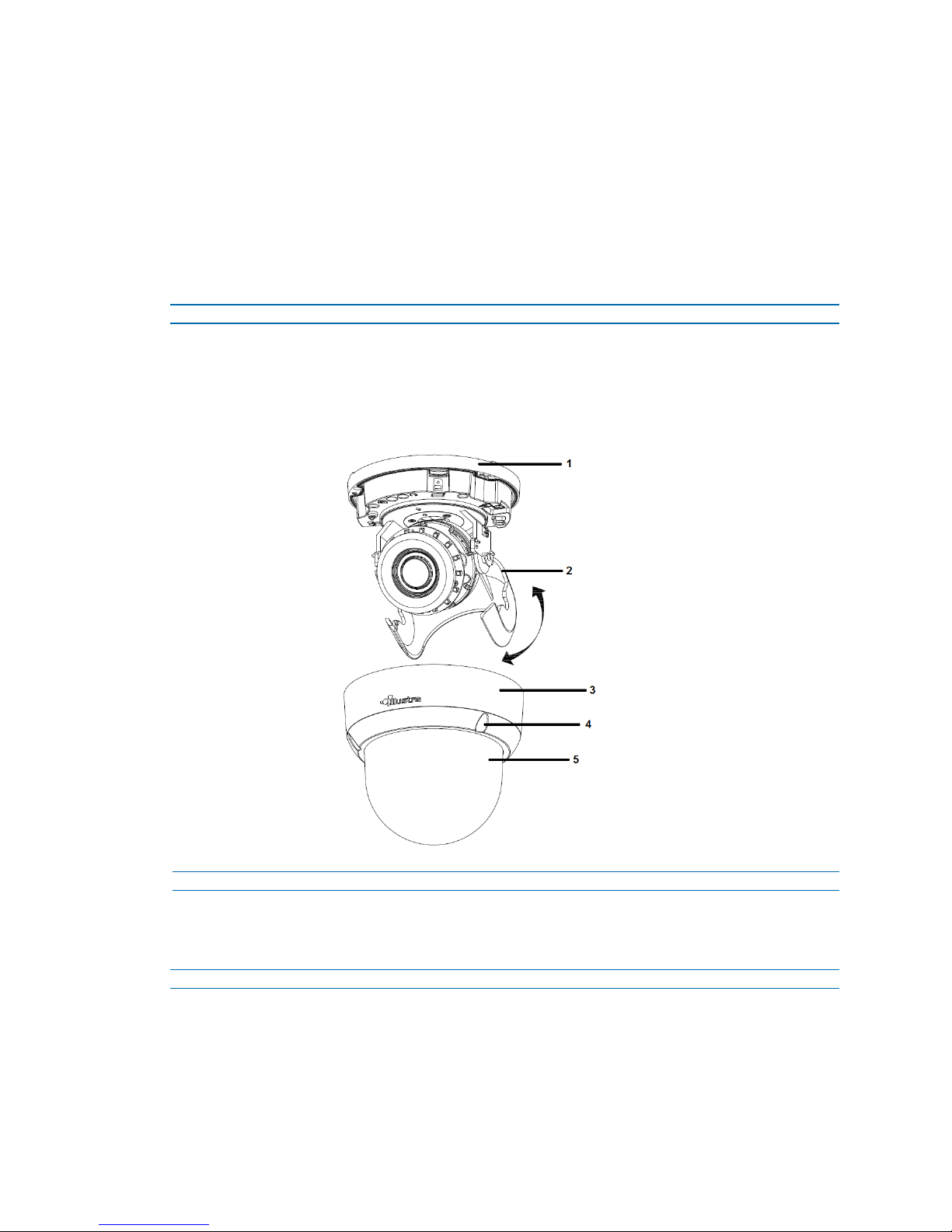
Procedure 6 Disassembling the Camera
Step Action
1 Remove the screws (4).
2 Gently remove the camera housing (3) and dome cover (5).
3 Set the camera housing aside.
Figure 21 Disassembling the outdoor camera
Procedure 7 Connecting the wires
Connect the power cable to the power plugs with one of the following options:
Step Action
1 AC 24V:
a Insert the power cable for AC 24V.
b Connect 24 V (~) cables to terminals ~AC 24V.
2 PoE:
8200-1456-02 E0 14
- End -
Page 19
Illustra Flex 3MP Indoor and Outdoor Dome Cameras Quick Start Guide
a Connect the RJ-45 jack to a PoE compatible network device that supplies power
through the Ethernet cable.
Note:The power source needs to be NEC Class 2 or LPS. The PoE connection should be provided
by a UL Listed product and the connections shall be made in accordance with Article 800 of the NEC
or local regulations.
- End -
Procedure 8 Mounting the camera
Step Action
1 Mark holes that correspond to the camera base on the mounting surface
2 Drill holes.
3 Fasten the anchors to the mounting surface with screws.
4 Connect the Safety Wire (fall prevention wire, not supplied) with one end to the ceiling and
the other to the safety-cord screw of the unit.
5 Secure the unit bottom case to the wall or ceiling with tapping screws.
6 Adjust the viewing angle.
WARNING
CAUTION
Procedure 9 Optional - 4S Electrical Junction Box
Step Action
1 Secure the mounting kit (optional) to 4S Electrical box using 2 appropriate screws.
2 Secure the unit case to mounting kit using 2 appropriate screws.
3 Tuck the cables in the 4S Electrical box.
4 Adjust the view angles.
5 Attach the unit housing.
6 Turn the power on after you install the unit.
Depending on the material of your mounting surface, you may require different screws and
anchors than those as supplied. To prevent the unit from falling off, ensure that it is secured to a
firm place (ceiling slab or channel) with a safety wire (not supplied) strong enough to sustain the
total weight of the unit. Pay also attention to the finishing at the end of the wire. Never turn the lens
more than 360°, which should disconnect or break internal cables.
Safety wire must be connected with one end to the ceiling and the other to the safety-cord screw of
the unit.
- End -
15 8200-1456-02 E0
Page 20
Illustra Flex 3MP Indoor and Outdoor Dome Cameras Quick Start Guide
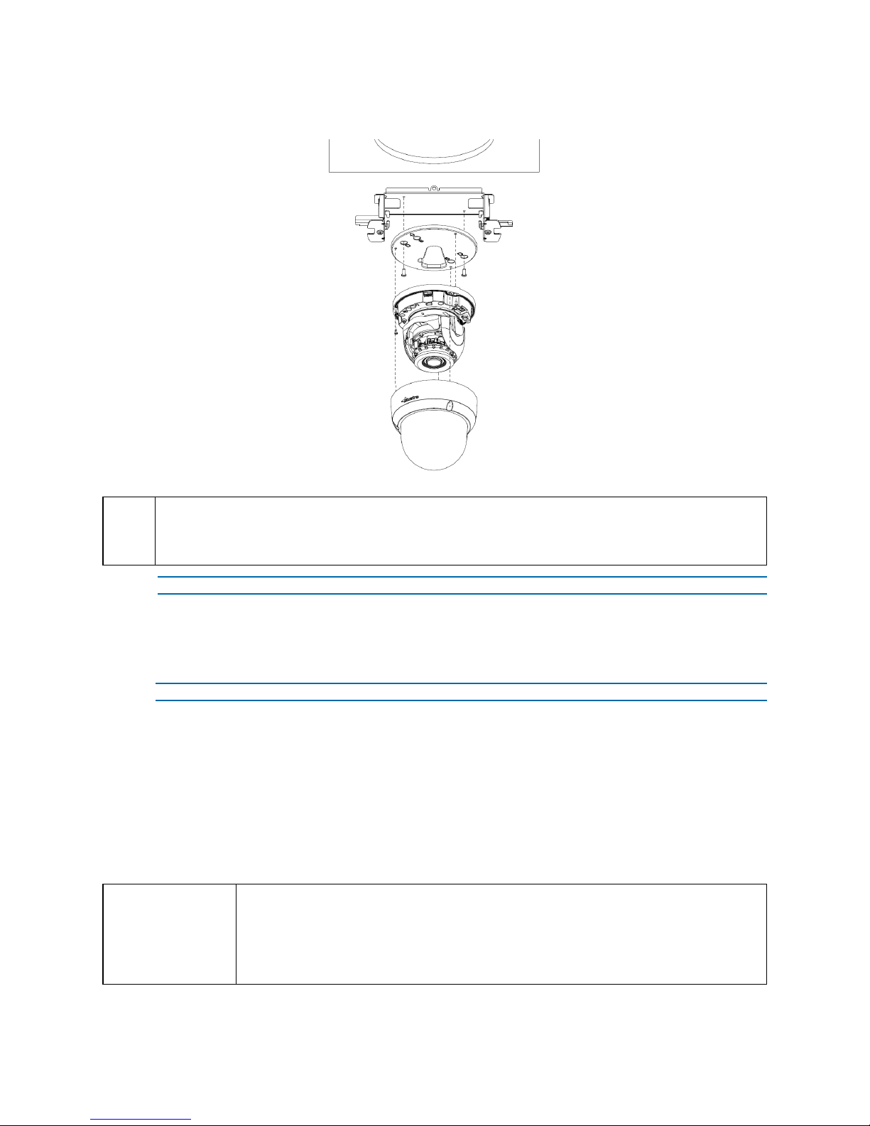
Figure 22 Mounting the camera with the junction box
NOTE
Procedure 10 Adjusting the Position
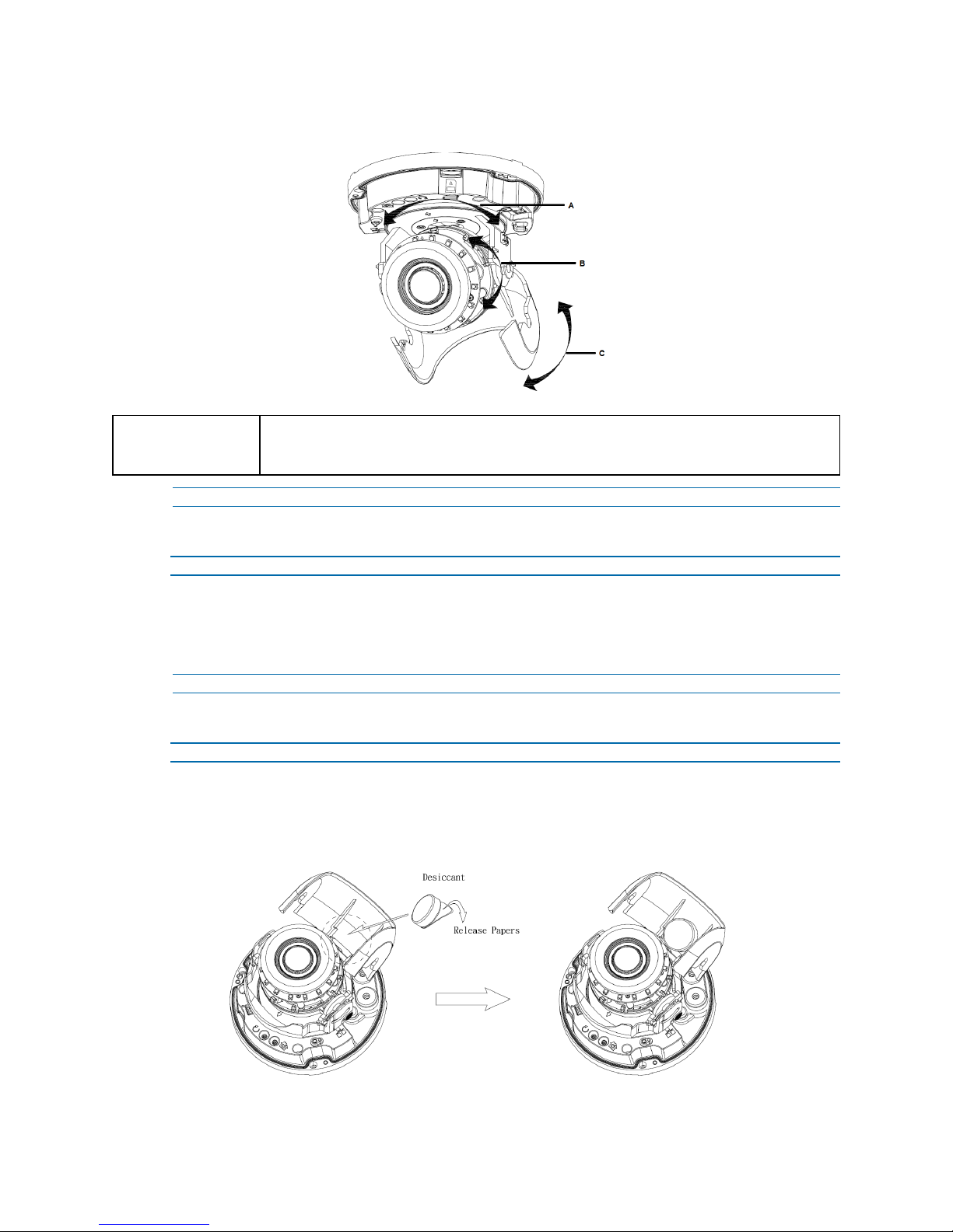
The unit has three axes for positioning, refer to Figure 23 on page 17. While monitoring, adjust the
position as below.
Step Action
CAUTION
The mounting kit called out in Figure 22 on page 16 is not supplied with the unit.
Keeping tilt angle over 25 degrees is recommended when IR-LED light is used. If tilt angel is below 25
degrees from the horizontal, the image would be flashed by the reflection of IR-LED light.
- End -
1 Pan Adjustment (A) For Wall Mount and Tilted Ceilings:
a Rotate the lens base (maximum 375°) until you are satisfied with the field of view.
2 Horizontal Rotation (B):
a Rotate 3D assembly in the base. Do not turn assembly more than 360° as this
assembly may cause the internal cables to twist and disconnect or break.
3 Tilt Adjustment (C):
a Tilt the lens base (maximum 90°) until you are satisfied with the field of view.
Limitation for three axes position:
• Pan range: 375°
• Tilt range: 75°
• Rotate range: Motorize Lens 356°
8200-1456-02 E0 16
Page 21
Illustra Flex 3MP Indoor and Outdoor Dome Cameras Quick Start Guide
Figure 23 Adjusting the position of the camera
NOTE
For outdoor Dome camera series:
Users can adjust zoom level and focus level using the Illustra Connect Web User
Interface.
- End -
Procedure 11 Locking the Camera
Step Action
1 Use a soft, lint-free cloth to wipe the dome cover and remove fingerprints.
2 Attach the inner liner and camera housing.
3 Turn the power on after you have install the unit.
- End -
Procedure 12 Applying the desiccant
Step Action
1 Remove the papers from the back of the desiccant.
2 Attach to the interior side of the tilt adjuster as seen in the image below.
Figure 24 Location for desiccant application
17 8200-1456-02 E0
Page 22
Illustra Flex 3MP Indoor and Outdoor Dome Cameras Quick Start Guide
System Requirements
The below table lists the minimum requirements to implement and operate Illustra Flex 3MP Indoor
and Outdoor Dome cameras.
Table 25 System Requirements
System hardware
CPU Intel Pentium 4 2.4GHz or equivalent
RAM 1 GB or above
Display NVIDIA GeForce 6 Series or ATI Mobility Radeon 9500
System software
Browser Microsoft Internet Explorer 9 or above, Firefox, Safari, Chrome
Unit
Power Supply AC 24V / PoE
Networking
Wired
NOTE All the installation and operations should comply with your local electricity safety rules.
CAUTION
To avoid damage to the unit, never connect more than one type of power supply (PoE IEEE802.3
Ethernet Class 0 or AC24V power plug) at the same time. If using PoE, this camera is to be
connecting only to PoE networks without routing to heterogeneous devices.
10/100BASE-T Ethernet (RJ-45 connector)
NOTE: A switch is required for surveillance on multiple units.
18 8200-1456-02 E0
Page 23
Illustra Flex 3MP Indoor and Outdoor Dome Cameras Quick Start Guide
Network Connection
Default IP Address
Since this is a network-based unit, an IP address must be assigned at the very first bootup. The
default IP address of the unit is 192.168.1.168 and sub mask is 255.255.255.0.
However, if you have a DHCP server in your network, the unit obtains an IP address automatically
from the DHCP server so that you do not need to change the IP address of the camera.
Note:If you assign the camera a Static IP address prior to DHCP being enabled, the camera first
reboots for approximately 30 seconds and then remains accessible at its Static IP until it connects to
a DHCP server.
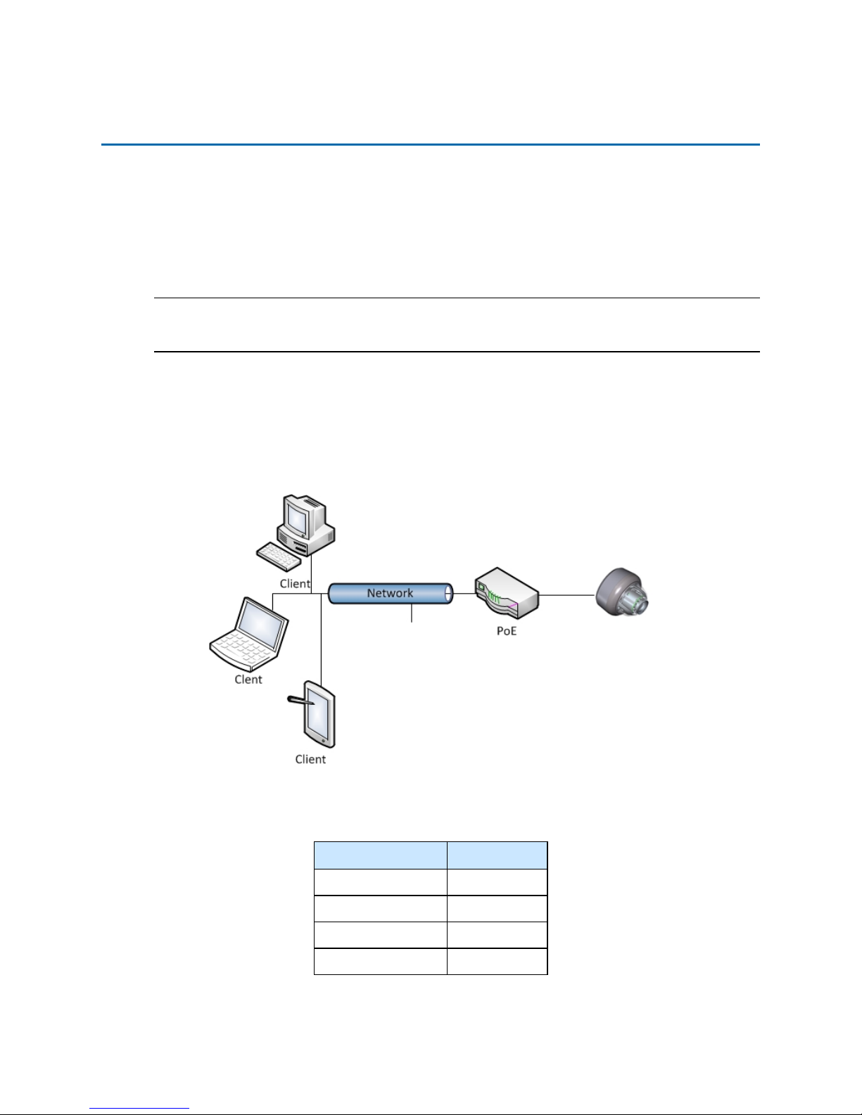
• Connect to a PC directly: Directly connect the camera to a PC using a standard Ethernet
cable.
• Connecting a camera to a Local Area Network (LAN): To add the camera to an existing
LAN, connect the camera to the hub or switch on your network. If you want to provide the
camera power using the Ethernet connection, a PoE-enabled hub or switch is required.
Figure 26 Network connection diagram
Default camera settings
The following table describes the default camera settings.
19 8200-1456-02 E0
Network Settings Defaults
DHCP Enabled
Static IPAddress 192.168.1.168
Default Username admin
Default Password admin
Page 24

Illustra Flex 3MP Indoor and Outdoor Dome Cameras Quick Start Guide
Procedure 13 Connecting from a computer
Step Action
1 Ensure the camera and your computer are in the same subnet.
2 Check whether if the network is available between the unit and the computer by pinging the
default IP address.
a Start a command prompt.
b Type “Ping 192.168.1.168”. If the message “Reply from…” appears, it means the con-
nection is available.
3 Start Internet Explorer and enter IP address: 192.168.1.168. A login window appears. In the
window, enter the default user name: admin and password: admin to log in.
- End -
DHCP
On initial camera startup, and after a hardware factory reset, Dynamic Host Configuration Protocol
(DHCP) is enabled by default and remains enabled until the camera receives either a DHCP address
or is assigned a Static IP address.
Procedure 14 Enable DHCP
Step Action
1 Select Setup on the Web User Interface banner to display the setup menus.
2 Select the TCP/IP tab in the Basic Configuration menu.
3 Select the Enable DHCP check box to enable DHCP and disable manual settings.
4 Select Apply to save the settings.
The camera searches for a DHCP server. If one is found it connects to that server. If no connection
is made to a DHCP server within two minutes, the camera goes to the default IP address
192.168.1.168, but continues to search for a DHCP address.
Note:If you assign the camera a Static IP address prior to DHCP being enabled, the camera first
reboots for approximately 30 seconds and then remains accessible at its Static IP until it connects to
a DHCP server.
- End -
Procedure 15 Disable DHCP
Step Action
1 Select Setup on the Web User Interface banner to display the setup menus.
2 Select the TCP/IP tab in the Basic Configuration menu.
3 Clear the Enable DHCP check box to disable DHCP and allow manual settings to be
entered.
The default setting is ‘Enabled’.
4 If Enable DHCP has been disabled:
8200-1456-02 E0 20
Page 25

Illustra Flex 3MP Indoor and Outdoor Dome Cameras Quick Start Guide
a Enter the IPv4 Address in the IPv4 Address text box in the form xxx.xxx.xxx.xxx.The
default setting is ‘192.168.1.168’
b Enter the Network Mask in the Network Mask text box xxx.xxx.xxx.xxx. The default
setting is ‘255.255.255.0’
c Enter the Gateway IP address in Gateway text box xxx.xxx.xxx.xxx.
d Enter the Primary DNS Server in the Primary DNS Server text box xxx.xxx.xxx.xxx.
5 Select Apply to save the settings.
- End -
Managing cameras with the Illustra Connect tool
In addition to using the IE browser to access your camera, you can alternatively use the provided
tool, Illustra Connect.
Illustra Connect is a management tool designed to manage your network cameras on the LAN. It can:
• help you find multiple network cameras
• set the IP addresses
• show connection status
• manage firmware upgrades
• bulk configuration
Procedure 16 Connecting to the camera using Illustra Connect
Note:
Illustra Connect can only discover devices on the same subnet as its host computer. Therefore, the
camera and the computer being used to configure it must be on the same subnet.
Step Action
1 Using a computer which is connected to the same network and subnet, install the Illustra
Connect software.
The Illustra Connect software and the Illustra Connect manual are available to download on
www.illustracameras.com
2 When the installation is complete, run Illustra Connect.
It searches the network and displays all compliant devices.
3 Select the camera you want to configure, locating it by its unique MAC address.
4 Right-click the camera and select Launch Web GUI Configuration. The camera Web User
Interface displays.
21 8200-1456-02 E0
- End -
Page 26

Illustra Flex 3MP Indoor and Outdoor Dome Cameras Quick Start Guide
Procedure 17 Connecting to the camera using the static IP address
Step Action
1 The camera attempts to obtain an IP Address from the DHCP Server. When no DHCP
Server is available the camera is assigned a Static IP address of 192.168.1.168.
2 Open Microsoft Internet Explorer and enter the URL of the camera as 192.168.1.168. The
camera sign in page displays.
Note:
The computer you use to configure the camera must have an IPaddress on the same subnet.
- End -
Procedure 18 Logging on to the camera web user interface
Step Action
1 When you select the camera, the sign in page displays. Select your preferred language from
the drop-down menu.
2 Enter the username in the Username text box. The default username is admin.
3 Enter the password in the Password text box. The default password is admin.
4 Select Log in.
5 The Live view page appears. This displays the current view of the camera.
Note:
To view the video pane the latest version of QuickTime must be installed and enabled on the
computer running the browser session.
- End -
Procedure 19 Enabling the correct video orientation for a wall mounted
camera
Step Action
1 Log on to the camera web user interface.
2 Select Setup on the camera web user interface banner to display the setup menus.
3 Select the Picture Basic tab from the Basic Configuration menu.
4 Select the required Orientation setting:
• Mirror
• Flip
5 The video pane updates to display the new settings.
8200-1456-02 E0 22
- End -
Page 27
Illustra Flex 3MP Indoor and Outdoor Dome Cameras Quick Start Guide
Network Topology
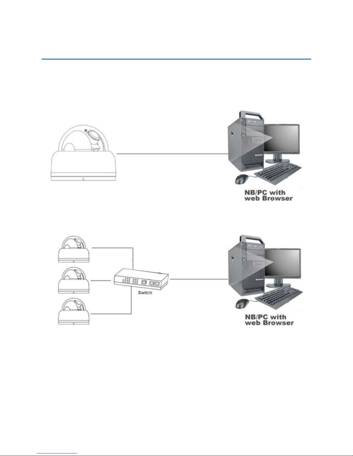
The Illustra Flex cameras deliver video images and audio in real-time using the Internet and Intranet.
It is equipped with an Ethernet RJ-45 network interface.
The following images illustrate the network topologies of the cameras.
Figure 27 Dome Cameras Network Topology Type I
Figure 28 Dome Cameras Network Topology Type II
23 8200-1456-02 E0
Page 28
Illustra Flex 3MP Indoor and Outdoor Dome Cameras Quick Start Guide
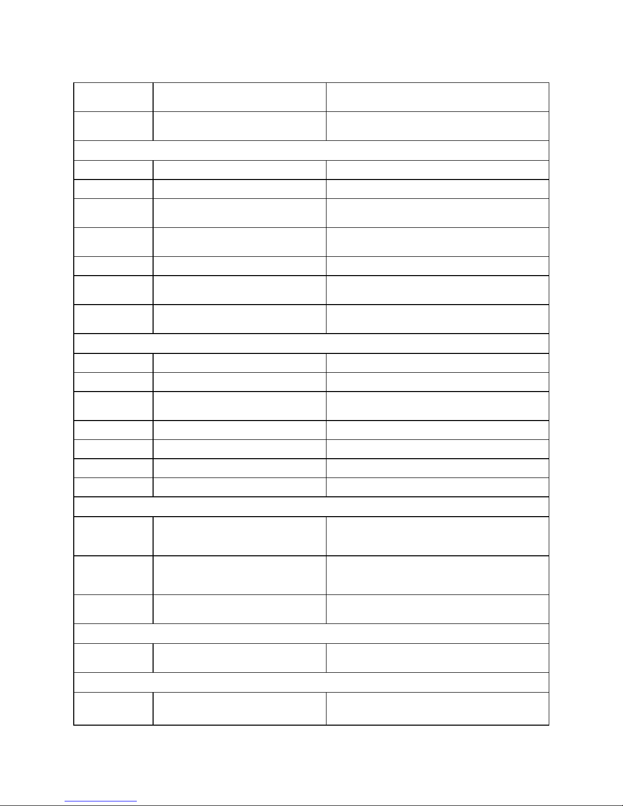
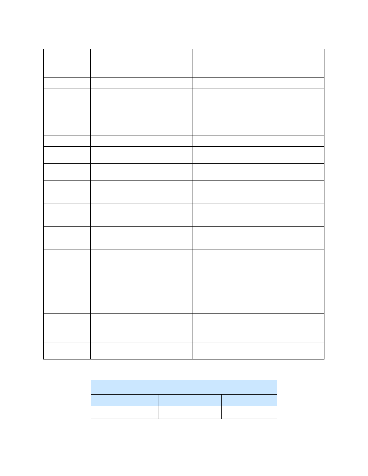
Appendix A: Technical Specifications
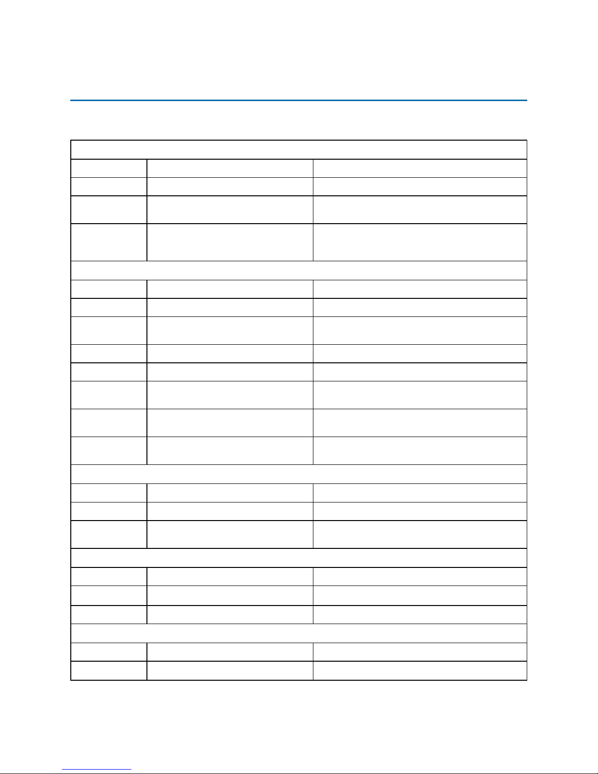
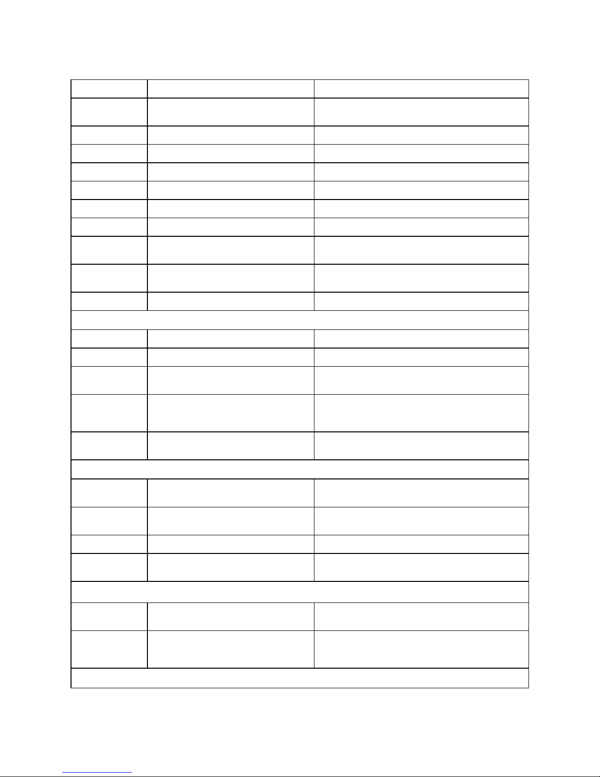
The table below lists technical specifications of the Flex 3MP Indoor and Outdoor Dome camera.
General Features
Model Type Indoor Mini-dome camera Outdoor Mini-Dome camera
Model No. IFS03D1ICWTT IFS03D1OCWIT
Camera Body
Color
Vandal
Resistant
Rating
White White
IK10 IK10
Mechanical Features
Dimensions Ø123x107mm Ø123x107mm
Weight approximately 0.7kg approximately 0.7kg
Pan Rotation
Angle
Tilt Angle 90° 75°
Z-axis Rotation 356° 356°
Housing
Material
Bubble Trim
Ring Material
Other Housing
Material
375° 375°
Aluminum Alloy Aluminum Alloy
ADC12 ADC12
PC/KE-951U PC/KE-951U
Video Processor
ROM/Flash Size 256 Mbytes 256 Mbytes
RAM Size 512 Mbytes 512 Mbytes
RTC Hold Up
Time
Format 1/2.8" CMOS 1/2.8" CMOS
Capture Method Rolling Rolling
Scan Method Progressive Progressive
Design Type Varifocal 6 groups 8 elements (1 aspheric glass lens)
Mount Phi 14mm Phi 14mm
24 hours 24 hours
24 8200-1456-02 E0
Image Sensor
Lens
Page 29
Illustra Flex 3MP Indoor and Outdoor Dome Cameras Quick Start Guide
Aperture Range F/1.4(W) ~ F/2.7(T) F/1.4(W) ~ F/2.7(T)
Focal Length
Range
Focal Means Motorized Motorized
Focal Type Varifocal Varifocal
Focus Type Motorized Motorized
Auto Focus One-Touch One-Touch
IR Correction N/A Optical corrected
Day/Night True D/N with ICR True D/N with ICR
Horizontal
Angle of View
Vertical Angle
of View
Format 1/2.7" 1/2.7"
2.8-12 mm 2.8-12 mm
98゚ (Wide); 35゚ (Tele) 98゚ (Wide); 35゚ (Tele)
71゚ (Wide); 26゚ (Tele) 71゚ (Wide); 26゚ (Tele)
Illuminator
Wavelength N/A 850 mm
IR Distance N/A 25m
Smart IR N/A
Yes. When Smart IR is ON, AE luma target will be
reduced slightly and applies some dWDR.
Adaptive IR N/A
Number of IR
LED devices
N/A 16PCS
Yes. Adaptive IR refers to lens position to adjust
the IR intensity of both narrow and broad IR LEDs
to have better exposure balance.
Power Supply
Power
Requirement
Current Draw
Amps
Wattage 5.9W 11.9W
Line Frequency
Range
AC 24V, PoE IEEE 802.3af class 3 AC 24V, PoE IEEE 802.3af class 3
0.338mA 0.688mA
47 to 63 Hz 47 to 63 Hz
Video Codecs
Frame Rate
Range
Maximum
Resolution and
Rate
1 to 60 ips 1 to 60 ips
3MP @ 30 ips 3MP @ 30 ips
Video Imaging
8200-1456-02 E0 25
Page 30
Illustra Flex 3MP Indoor and Outdoor Dome Cameras Quick Start Guide
Dynamic Range
Method
Noise
Reduction
True WDR True WDR
2D and 3D NR Noise Reduction
Audio
Sampling Bits 16-BIT 16-BIT
Input Type SE/Line/MIC SE/Line/MIC
Input
Impedance
Maximum Input
Level
Input connector Terminal Block Terminal Block
Output Type
Impedance
Maximum
Output
20K/Attenuation = 0 dB 20K/Attenuation = 0 dB
2Vp-p 2Vp-p
Hi impedance Hi impedance
2Vp-p 2Vp-p
I/O Interfaces
SD Card SDXC slot up to 128GB SDXC slot up to 128GB
Alarm Inputs 1 1
Auxiliary
Outputs
Video Output Yes Yes
IP Connector RJ-45 RJ-45
LED Indicators Network, Green LED, Orange LED Network, Green LED, Orange LED
Reset Buttons Reboot and Return to Defaults Reboot and Return to Defaults
1 1
Environmental
Operating
Temperature
Range
Start-up
Temperature
Range
Water/Dust
Intrusion
-20° ~+50°C -50° ~ +50°C
-20° ~+50°C -40° ~ +50°C
N/A IP66/67
Client Interfaces
Browsers
supported
IE 9 or above, Firefox,Safari, Chrome IE 9 or above, Firefox,Safari, Chrome
Networking
Languages
supported
English (default), Arabic, Czech,
Danish, German, Spanish, French,
26 8200-1456-02 E0
English (default), Arabic, Czech, Danish, German,
Spanish, French, Hungarian, Italian, Korean,
Page 31
Illustra Flex 3MP Indoor and Outdoor Dome Cameras Quick Start Guide
Hungarian, Italian, Korean, Japanese,
Netherlands, Polish, Portuguese,
Swedish, Turkish, Chinese Traditional,
Chinese Simplified.
Ethernet 10/100Base-T 10/100Base-T
TCP/IP, IPv4, IPv6, TCP, UDP, HTTP,
FTP, DHCP, WS-Discovery, DNS,
Supported
Protocols
Base Protocol TCP/IP - RFC4614 TCP/IP - RFC4614
Internet Layer
Addressing
Transport Layer
Data
Transmission
Network
Address
Configuration
DDNS, RTP, TLS, Unicast, Multicast,
NTP, SMTP, WSSecurity, IEEE 802.1x,
PEAP, SSH, HTTPS, SSL, SOAP,
WSAddressing, CIFS, SNMP, UPnP,
RTSP, LLDP
IPv4 - RFC791
IPv6 - RFC2460
TCP - RFC973
UDP - RFC768
HTTP/HTTPS - RFC2616
FTP - RFC959
SFTP
DHCP - RFC2131 Zeroconf RFC3927 Static IP address
LLDP
Japanese, Netherlands, Polish, Portuguese,
Swedish, Turkish, Chinese Traditional, Chinese
Simplified.
TCP/IP, IPv4, IPv6, TCP, UDP, HTTP, FTP, DHCP,
WS-Discovery, DNS, DDNS, RTP, TLS, Unicast,
Multicast, NTP, SMTP, WSSecurity, IEEE 802.1x,
PEAP, SSH, HTTPS, SSL, SOAP, WSAddressing,
CIFS, SNMP, UPnP, RTSP, LLDP
IPv4 - RFC791
IPv6 - RFC2460
TCP - RFC973
UDP - RFC768
HTTP/HTTPS - RFC2616
FTP - RFC959
SFTP
DHCP - RFC2131 Zeroconf - RFC3927 Static IP
address
LLDP
Time
Synchronization
E-mail
Authentication
and Security
Streaming
Firmware
Upgrade
NTP - RFC1305
IETF NTP Working Group
i minute poll rate
SMTP - RFC5321
Authenticated SMTP - RFC4954
IEEE.802.1x - TLS/PEAP
HTTPS (HTTP over TLS) - RFC2818
WS-Security
Multi-level password protection
IP address filtering
HTTPS encryption
User access log
RTP - RFC3550
RTSP - RFC2326
Unicast Streaming
Multicast RFC 1112 level 1
Browser/illustra Connect/ONVIF Browser/illustra Connect/ONVIF
NTP - RFC1305
IETF NTP Working Group
i minute poll rate
SMTP - RFC5321
Authenticated SMTP - RFC4954
IEEE.802.1x - TLS/PEAP
HTTPS (HTTP over TLS) - RFC2818
WS-Security
Multi-level password protection
IP address filtering
HTTPS encryption
User access log
RTP - RFC3550
RTSP - RFC2326
Unicast Streaming
Multicast RFC 1112 level 1
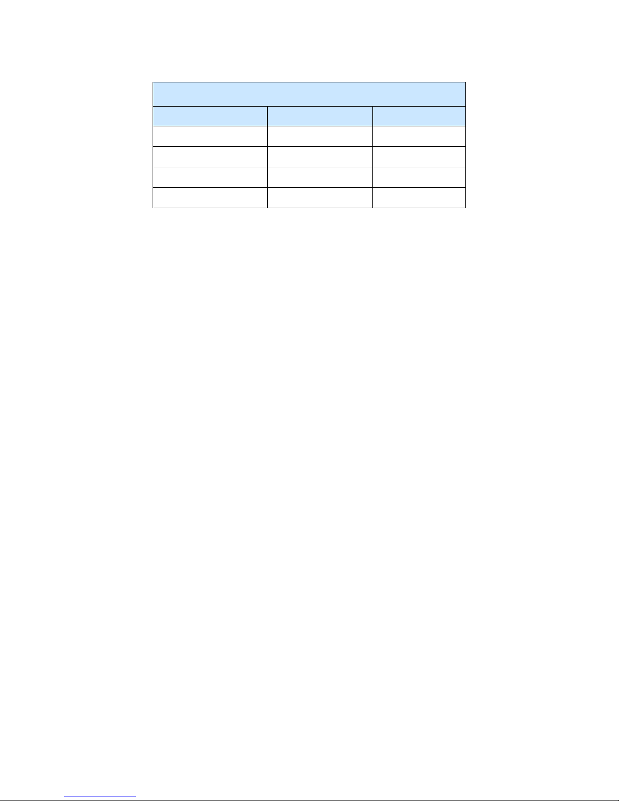
Indoor and Outdoor Dome camera resolutions
Stream 1 Stream 2 Stream 3
(2048x1536) QXGA 4:3 (1280x720) 720p 16:9 (480x360) 480 4:3
8200-1456-02 E0 27
Page 32
Illustra Flex 3MP Indoor and Outdoor Dome Cameras Quick Start Guide
Indoor and Outdoor Dome camera resolutions
Stream 1 Stream 2 Stream 3
(1920x1080) 1080p 16:9 (1024x576) PAL+ 16:9 (384x288) 4:3
(1664x936) 16:9 (640x360) nHD 16:9
(1280x720) 720p 16:9 (480x360) 480 4:3
(384x288) 4:3
28 8200-1456-02 E0
 Loading...