

Iliving ILG8FV110, ILG8FV112, ILG8FV111 User Manual
Model No.
6
Ventilating Fan
INSTALLATION INSTRUCTIONS
ILG8FV110 ILG8FV111
ILG8FV112
READ AND SAVE THESE INSTRUCTIONS
Thank you very much for purchasing our ventilating fan.
Please read these instructions carefully before attempting to install,
operate or service our ventilating fan. Failure to comply
with instructions could result in personal injury or property
damage. Please retain this booklet for future reference.
TABLE OF CONTENTS
UNPACKING
SUPPLIED ACCESSORIES
DESCRIPTION
GENERAL SAFETY INFORMATION
DIMENSIONS
WIRING DIAGRAM
FEATURE
INDICATION (PLUG AND PLAY FUNCTION DEVICES)
INSTALLATION (NEW CONSTRUCTION)
INSTALLATION (RETROFIT)
MAINTENANCE (CLEANING)
PRACTICAL GUIDE TO INSTALLATION
SPECIFICATIONS
..............................................................................................................
.......................................................................................
..........................................................................................................
........................................................................
............................................................................................................
...................................................................................................
..................................................................................................................
...........................................
Ⅰ
Ⅱ
......................................................................................................
.................................................................................
...................................................................................
.............................................................
...................................................................
02
02
02
03
04
05
05
06
07
11
13
14
14
UNPACKING
Unpack and carefully remove the unit from carton.
Refer to the supplied accessories list to verify that all parts are present.
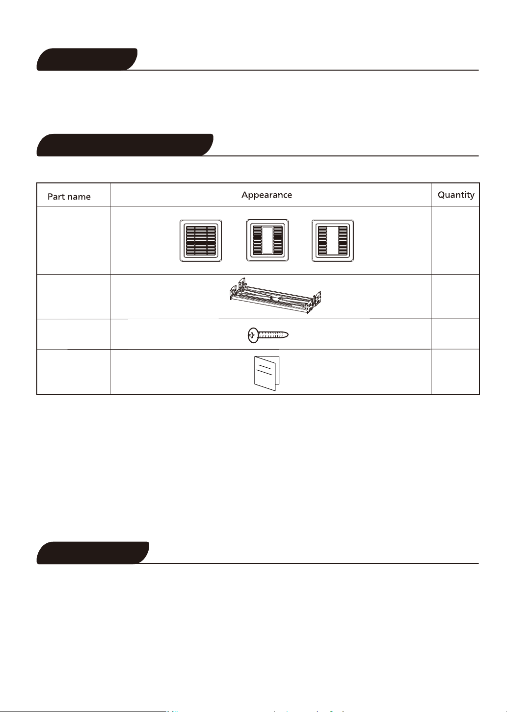
SUPPLIED ACCESSORIES
Louver
Suspension
bracket
assembly
Long screw
(ST4X30)
Installation
instructions
or
or
1
1
5
1
DESCRIPTION
These ventilating fan models are listed by ETL under ETL file No.5011292.
These ventilating fan models use a sirocco fan driven by a brushless DC motor.
The motor is designed to have an extended service life with reduced energy consumption.
The louver covering the fan body is a spring-loaded,quick remove type. A damper for preventing air
counterflow is provided.
The suspension bracket assembly can be used for both new construction and retrofit situation.
The light uses high brightness SMD LED as light source to ensure the performance.
2
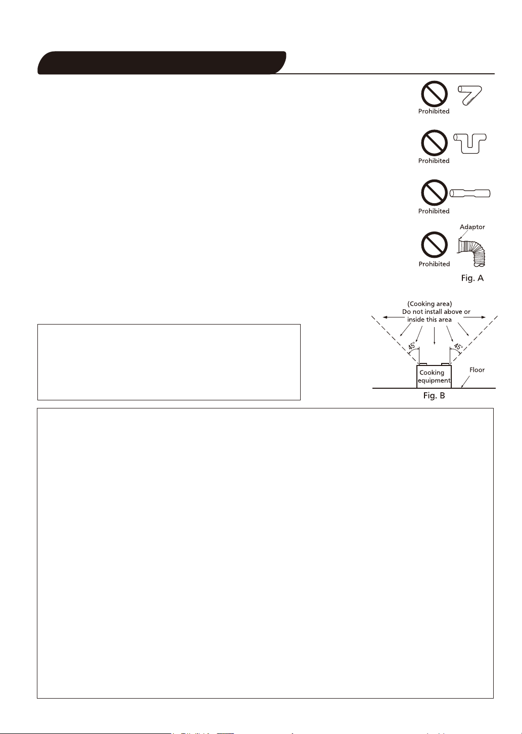
GENERAL SAFETY INFORMATION
Do not install this ventilating fan where interior room temperature may exceed
1.
104°F (40°C).
Make sure that the electric service supply voltage is AC 120V, 60Hz.
2.
Follow all local electrical and safety codes, as well as the National Electrical
3.
Code (NEC) and the Occupation Safety and Health Act (OSHA).
Always disconnect the power source before working on or near the fan, motor,
4.
light fixture or junction box.
Protect the power cord from sharp edges, oil, grease, hot surfaces, chemicals
5.
or other objects.
Do not kink the power cord.
6
Do not install the unit where ducts are configured as shown in Fig.A.
7.
Provide make up air for proper ventilation.
8.
A statement to the effect that when the product is to no longer
9.
be used, it must not be left in place but removed, to prevent it
from possibly falling.
CAUTION:
1.For general ventilating use only. Do not use to exhaust
hazardous or explosive materials and vapors.
2.Not for use in cooking area. (Fig.B)
3.This product must be properly grounded.
WARNING:
To reduce the risk of fire, electric shock or injury to persons, observe the following:
1.
Use this unit only in the manner intended by the manufacturer. If you have any questions, contact
with the manufacturer.
2.
Before servicing or cleaning unit, switch power off at service panel and lock the service
disconnecting means to prevent power from being switched on accidentally. When the service
disconnecting means cannot be locked, securely fasten a prominent warning device, such as a
tag, to the service panel.
3.
Installation work and electrical wiring must be done by qualified person(s) in accordance with
all applicable codes and standards, including fire-rated construction.
4.
Sufficient air is needed for proper combusition and exhausting of gases through the flue (chimney)
of fulel burning equipment to prevent back drafting. Follow the heating equipment manufacture′s
guideline and safety standards such as those pulished by the National Fire Protection Association
(NFPA), and the Ameriacan Society of Heating, Refrigration, and air conditioning Engneers
(ASHRAE) and the local code authorities.
5.
When cutting or drilling into wall or ceiling, do not damage electrical wiring and other hidden
utilities.
6.
Ducted fans must always be vented to the outdoors.
7.
If this unit is to be installed over a tub or shower, it must be marked as appropriate for the
application and be connected to a GFCI (Ground Fault Circuit Interrupter)-protected branch circuit.
8.
These models are ETL listed for tub and shower enclosures.
9.
Not to be installed in a celling thermally insulated to a value greater than R40. (This is required for
installation in Canada only).
3
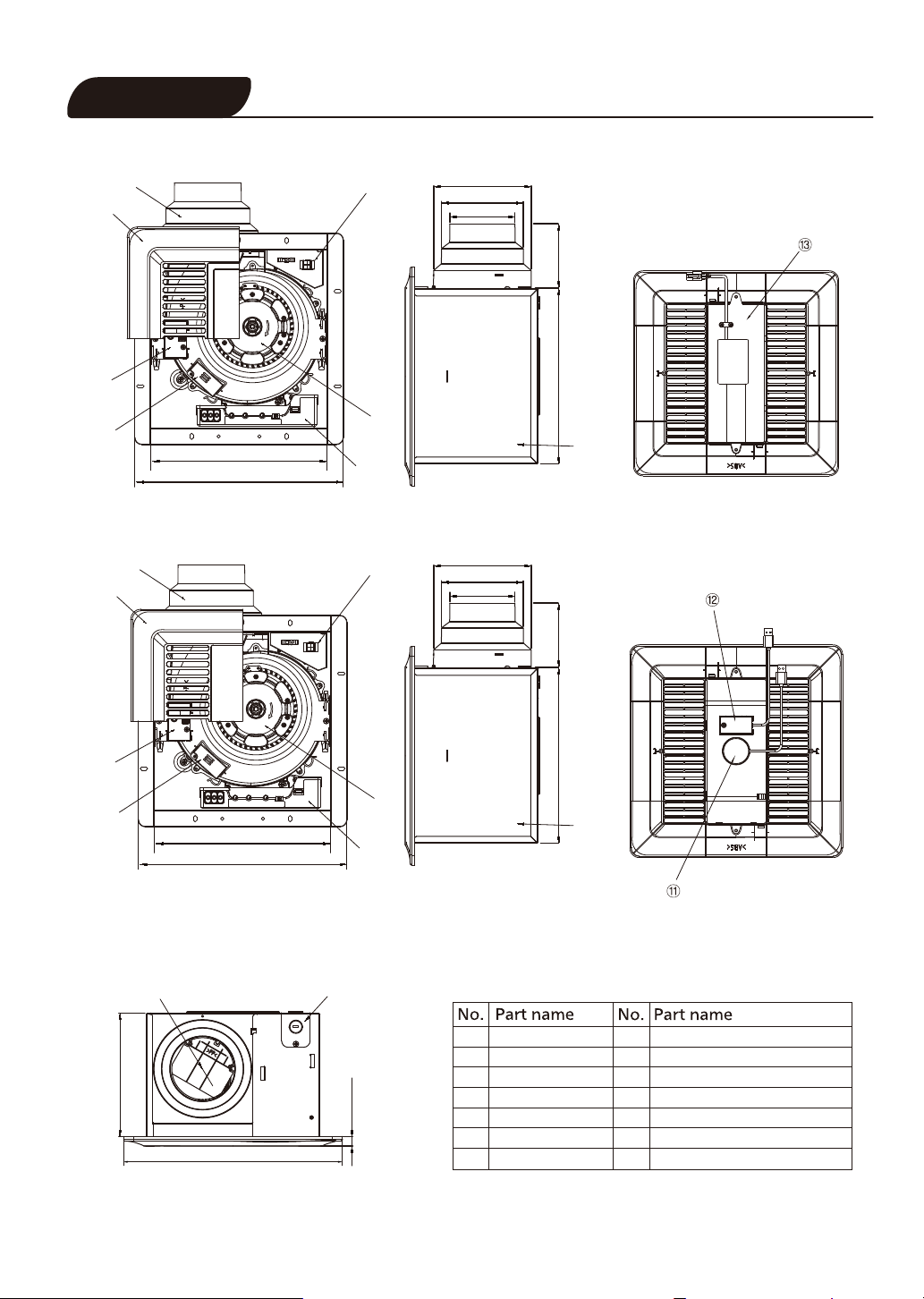
DIMENSIONS
Model: ILG8FV111
③
②
⑨
⑩
Model: ILG8FV112
③
②
10 1/4 (260)
12 1/8 (308)
Unit: inches(mm)
⑦
5 4/5 (147)
4 7/8 (123)
3 7/8 (98)
3 4/5 (97)10 2/5 (265)
①
⑤
⑧
⑦
5 4/5 (147)
4 7/8 (123)
3 7/8 (98)
3 4/5 (97)10 2/5 (265)
⑨
①
⑩
7 1/3 (186)
10 1/4 (260)
12 1/8 (308)
④
13 (330)
⑥
⑧
3/5 (14.5)
Blade
1
Louver
2
Adaptor
3
Damper
4
Frame assy
5
Knockout plate
6
Junction box
7
⑤
Base PCB box
8
Humidity sensor module
9
CO sensor module
10
2
Night light module
11
Motion sensor module
12
LED light
13
4

WIRING DIAGRAM
Model: ILG8FV110/ LG8FV112
Fan body
Motor
Yellowgreen
Junction box
P
C
B
White
Red
Red
Black
Green
Neutral
Signal
Signal
Live
Earth ground
FEATURE
Multi-Speed
Flow-Selection
Air Volume(CFM)
50
80 110
80
70
90
60
50
0
Time delay
Air trimming
Air Trimming
Time(min)
H
30
20
L
10
45
100
5
60
0
Model: ILGFV111
Control switch
Power switch
Fan body Junction box
White
Motor
Yellowgreen
Light Body
P
C
B
Red
Red
Black
Green
Brown
White
Blue
Neutral
Signal
Signal
Live
Earth ground
Live (Light)
Neutral
Live(N. Light)
Control switch
Power switch
All fans come with Flow-Selection speed switch, Multi-Speed switch,
Time Delay switch and Air Trimming switch.
●Flow-Selection. The switch with choosing option 50-80-110CFM is
set on the PCB box and is default high speed.
●Multi-Speed. The switch allows the fan to run at the lower speeds
continuously to meet Indoor Air Quality. As an example, when
Flow-Selection setting is 80CFM, Multi-Speed can be chosen 0, 50,
60, or 70CFM as a low speed.
●Time Delay. The switch is for time delay setting. Setting range is 0,
5, 10, 20, 30, 45 or 60 minutes.
●Air Trimming switch. The switch is for micro-adjusting the air volume
when the actual airflow is lower than set.
INSTRUCTIONS:
Firstly, the power switch should be turned on.
①When the control switch is turned on, the fan runs at high speed continuously only. The sensors will
not work and Time delay switch does not apply to this mode.
②When the control switch is turned off, the fan runs at chosen low speed on Multi-Speed switch
continuously, and boosts in high speed when the sensor detects. The fan runs at high speed for
amount of time that selected from the Time Delay switch before returning to low speed when the
sensor stops detection.
5
 Loading...