

Page 1
System Reference Guide
January 2008
Publication AP6526
iLive and T Series
System Reference Guide
March 2009
Firmware Version 1.4
Publication AP6526 issue 3
Page 2

Limited Two Year Warranty
This product has been manufactured in the UK by ALLEN & HEATH and is
warranted to be free from defects in materials or workmanship for a period of two
years from the date of purchase by the original owner.
To ensure a high level of performance and reliability for which this equipment has
been designed and manufactured, read this User Guide before operating.
In the event of a failure, notify and return the defective unit to ALLEN & HEATH or
its authorised agent as soon as possible for repair under warranty subject to the
following conditions:
Conditions Of Warranty
1. The equipment has been installed and operated in accordance with the
instructions in the equipment User Guides
2. The equipment has not been subject to misuse either intended or accidental,
neglect, or alteration other than as described in the User Guide or Service
Manual, or approved by ALLEN & HEATH.
3. This warranty does not cover fader wear and tear.
4. Any necessary adjustment, alteration or repair has been carried out by
ALLEN & HEATH or its authorised agent.
5. The defective unit is to be returned carriage prepaid to ALLEN & HEATH or its
authorised agent with proof of purchase.
6. Units returned should be packed to avoid transit damage.
In certain territories the terms may vary. Check with your ALLEN & HEATH agent
for any additional warranty, which may apply.
The iLive range of products complies with the European
Electromagnetic Compatibility directives 89/336/EEC &
92/31/EEC and the European Low Voltage Directives
73/23/EEC & 93/68/EEC.
Any changes or modifications to the equipment not approved by Allen
& Heath could void the compliance of the product and therefore the
users authority to operate it.
iLive System Reference Guide AP6526 Issue 3
Copyright © 2009 Allen & Heath. All rights reserved
ALLEN&HEATH
Manufactured in the United Kingdom by Allen & Heath Limited
Kernick Industrial Estate, Penryn, Cornwall, TR10 9LU, UK
http://www.allen-heath.com
2 ALLEN&HEATH iLive Reference Guide AP6526 iss.3
Page 3
Important Safety Instructions
WARNINGS - Read the following before proceeding :
CAUTION
ATTENTION: RISQUE DE CHOC ELECTRIQUE – NE PAS
OUVRIR
Read instructions: Retain these safety and operating instructions for future reference.
Adhere to all warnings printed here and on the equipment. Follow the
operating instructions printed in this User Guide.
Do not remove covers: Operate the equipment with its covers correctly fitted. Refer any
service work on the equipment to competent technical personnel only.
Power sources: Connect the equipment to a mains power supply only of the type
described in this User Guide and marked on the rear panel. Use only
the power cord with sealed mains plug appropriate for your local
mains supply as provided with the equipment. If the provided plug
does not fit into your outlet consult your service agent for assistance.
Power cord routing: Route the power cord so that it is not likely to be walked on, stretched
or pinched by items placed upon or against it.
Grounding: Do not defeat the grounding and polarisation means of the power
cord plug. Do not remove or tamper with the ground connection in
the power cord.
WARNING: This equipment must be earthed.
Water and moisture: To reduce the risk of fire or electric shock do not expose the
equipment to rain or moisture or use it in damp or wet conditions. Do
not place containers of liquid on it which might spill into any openings.
Ventilation: Do not obstruct the ventilation slots or position the equipment where
the air flow required for ventilation is impeded. If the equipment is to
be operated in a flightcase ensure that it is constructed to allow
adequate ventilation.
Heat and vibration: Do not locate the equipment in a place subject to excessive heat or
direct sunlight as this could be a fire hazard. Locate the equipment
away from any devices which produce heat or cause excessive
vibration.
Servicing: Switch off the equipment and unplug the power cord immediately if it
is exposed to moisture, spilled liquid, objects fallen into the openings,
the power cord or plug become damaged, during lightening storms,
or if smoke, odour or noise is noticed. Refer servicing to qualified
technical personnel only.
Installation: Install the equipment in accordance with the instructions printed in this
User Guide. Use the equipment connections for their intended
purpose only.
ALLEN&HEATH iLive Reference Guide AP6526 iss.3 3
Page 4

Important Mains plug wiring instructions.
The equipment is supplied with a moulded mains plug fitted to the AC
mains power lead. Follow the instructions below if the mains plug has
to be replaced.
The wires in the mains lead are coloured in accordance with the
following code:
L LIVE BROWN BLACK
N NEUTRAL BLUE WHITE
E EARTH GND GREEN & YELLOW GREEN
The wire which is coloured Green and Yellow must be connected to
the terminal in the plug which is marked with the letter E or with the
Earth symbol. This appliance must be earthed.
The wire which is coloured Blue must be connected to the terminal in
the plug which is marked with the letter N.
The wire which is coloured Brown must be connected to the terminal
in the plug which is marked with the letter L.
Ensure that these colour codes are followed carefully in the event of
the plug being changed.
Precautions
TERMINAL
WIRE COLOUR
European USA/Canada
Damage : To prevent damage to the equipment cosmetics, avoid placing heavy
objects on the unit, scratching the surface with sharp objects, or
subjecting the unit to rough handling and vibration.
Environment : Protect from excessive dirt, dust, heat and vibration when operating
and storing. Avoid tobacco ash, smoke, drinks spillage, and exposure
to dust, rain and moisture. If the equipment becomes wet, switch off
and remove power immediately. Allow to dry out thoroughly before
using again.
Cleaning : Avoid the use of chemicals, abrasives or solvents. The equipment is
best cleaned with a soft brush and dry lint-free cloth. If the ventilation
grilles become blocked with dust use a vacuum cleaner to suck the
dirt out. Do not remove the cover to clean the unit.
Transporting : The equipment should be transported in the original packing or
purpose built flightcase to protect it from damage during transit.
Cables: Plan the location of the equipment so that the connecting cables are
not fully extended. Full extension of the cables can stress the
equipment and cables and may result in undesired performance.
Ensure that the cables are located such that they cannot be stood on
or tripped over.
Modules: Do not remove the modules from the equipment while power is
applied.
4 ALLEN&HEATH iLive Reference Guide AP6526 iss.3
Page 5

This is the iLive System Reference Guide relating to Version 1.4 Firmware. The system firmware is
updated on a regular basis as new features and improvements are added. Some of the screen shots and
details in this guide may differ from those in the current release of firmware. Please refer to the Release
Notes that come with each version of firmware for details of new features.
Table of Contents
Introduction ................................................................................................. 7
iLive System components .......................................................................... 8
iDR10 MixRack............................................................................................ 9
iLive Surface ............................................................................................. 10
T Series System components .................................................................. 11
T Series Control layout............................................................................. 12
Connecting the iLive MixRack and Surface ............................................. 13
Connecting the T Series MixRack and Surface ...................................... 15
Booting up the system .............................................................................. 16
The Status screen...................................................................................... 17
Surface basics – The TouchScreen .......................................................... 19
Surface basics – Fader control strip ......................................................... 22
Surface basics – the SEL key ................................................................... 25
Surface basics – the MIX key.................................................................... 30
Channel and Mix processing .................................................................... 33
Introducing the FX ..................................................................................... 39
Patching the Outputs ................................................................................ 46
Using DCA groups .................................................................................... 48
Creating Mute Groups............................................................................... 48
Channel Ganging ...................................................................................... 49
COPY / PASTE / RESET edit keys ............................................................ 50
The METERS screen ................................................................................. 52
The RTA ..................................................................................................... 52
PAFL monitor system ................................................................................ 53
Solo-in-Place ............................................................................................. 54
Engineer’s Wedge/IEM monitoring........................................................... 57
Talkback system........................................................................................ 58
Soft Keys, PL-Anet, MIDI ........................................................................... 60
MIXRACK config and setup....................................................................... 61
Main mix types........................................................................................... 64
Direct output setup.................................................................................... 65
Audio sync / Network setup ...................................................................... 65
Signal generator ........................................................................................ 67
SURFACE setup ........................................................................................ 68
Assigning Surface strips............................................................................ 69
ALLEN&HEATH iLive Reference Guide AP6526 iss.3 5
Page 6

Assigning SoftKeys ................................................................................... 70
Assigning PL devices ................................................................................ 71
The Surface ALT VIEW key ....................................................................... 72
Setting Surface preferences...................................................................... 73
NAME and COLOUR ................................................................................. 74
User Profiles .............................................................................................. 75
Library memories....................................................................................... 76
Scene memories ....................................................................................... 77
Show memories......................................................................................... 78
Using Template Shows ............................................................................. 82
USB Scene transfer ................................................................................... 83
Working with USB data ............................................................................. 84
The UTILITY screen ................................................................................... 85
Lock the Surface ....................................................................................... 85
Change User ............................................................................................. 85
Help manual .............................................................................................. 85
Power down the TouchScreen.................................................................. 85
Configuration page.................................................................................... 86
Diagnostics page....................................................................................... 86
Firmware versions and update.................................................................. 87
Network setup and connections ............................................................... 88
iLive module options – Analogue inputs and outputs .............................. 89
iLive module options – Digital inputs and outputs.................................... 90
iLive module options – Digital multi-output............................................... 91
iLive module options – System ................................................................. 92
MIDI specification ...................................................................................... 94
Technical specification.............................................................................. 95
Weights and dimensions........................................................................... 98
System block diagrams........................................................................... 101
EtherSound system diagram .................................................................. 103
Application diagrams .............................................................................. 104
6 ALLEN&HEATH iLive Reference Guide AP6526 iss.3
Page 7

Welcome
Thank you for investing in the Allen & Heath iLive digital mixing system. To get the most from your iLive
please read the Getting Started Guide that comes with your system and refer to this reference guide for
further information.
The Allen & Heath web site provides the latest version of firmware and additional downloadable
information on iLive. To benefit from the latest features and improvements please check that you are
running up to date firmware. Full instructions on downloading and installing the firmware is available on
our web site www.allen-heath.com. If you cannot locate the information you are looking for in the
documentation please contact your local Allen & Heath agent.
Note: iLive is an evolving system. Through firmware upgrades new features and capability
compatible with your existing hardware are scheduled to be added over time.
Read the release notes that come with each new version of firmware. They provide a description and
information relating to new features, details of improvements, and notes about known issues.
Introduction to iLive
iLive and the iLive-T Series provide a modular system for live sound mixing. Allowing distributed control
and audio over CAT5 cable, iLive is well suited to demanding live sound applications such as
FOH/Monitor mixing, live recording and multi-function installed venue sound. It is uniquely flexible with
choice of components, a fully configurable bus architecture and assignable user interface for easy
configuration to match each application.
The standard iLive offers a fully modular construction and feature set suitable for the top end application,
and is available with a touring grade flightcase. The T Series offers an affordable fixed format solution for
the more budget conscious application. Both feature separate MixRack and control Surface with CAT5
digital link. The hardware, firmware and user data is compatible between the two systems.
The MixRack is the heart of the system with choice of modular or fixed I/O, 64 channel x 32 bus DSP
processing and network interfacing in a 19” rack frame. It has plenty of DSP power. All the processing is
available all the time including graphic EQ on all mix outputs, 3 dynamics processors per channel and 8
fully assignable FX racks. Four versions of MixRack are available including a compact MiniRack without
audio I/O for digital split systems.
The Surface is a ‘controller’ that allows remote control of the MixRack and other components in the
system. It has audio I/O built in for local audio signals to connect with the MixRack via CAT5 cable using
EtherSound or the Allen & Heath ACE link. The purpose designed user interface gives you instant access
to all your live mixing functions with plenty of faders, single button access analogue style channel
processing control as well as an intuitive touch screen. Between them iLive and the T Series provide no
fewer than 6 different versions of Surface giving you a choice of number of faders and price point to
match your application.
iLive offers a host of control possibilities including the Surface, networked or wireless laptops or touch
tablets running iLive Editor software, PL Series remote controllers, MIDI and more. You can even leave
your Surface at home and run the show with just a laptop connected to the MixRack. iLive marries a new
generation of digital mixing with the speed of operation and sound quality expected of the best analogue
consoles.
ALLEN&HEATH iLive Reference Guide AP6526 iss.3 7
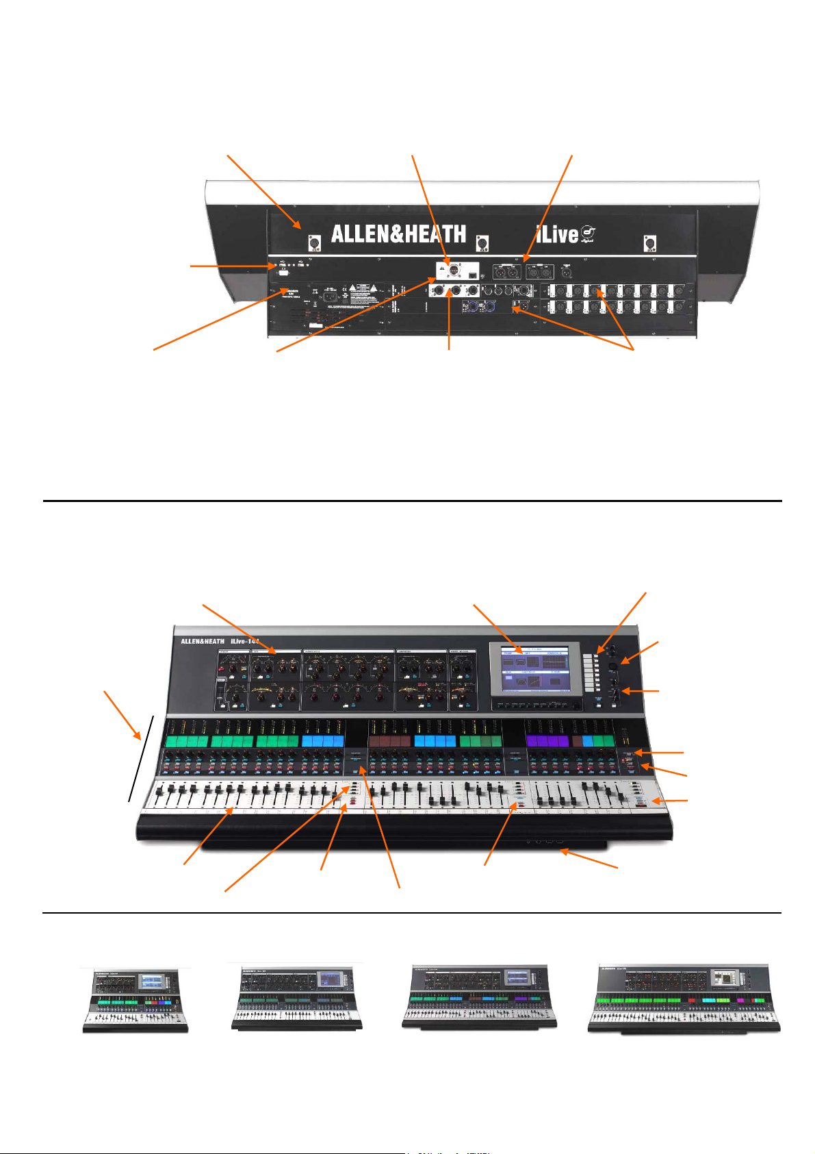
Page 8
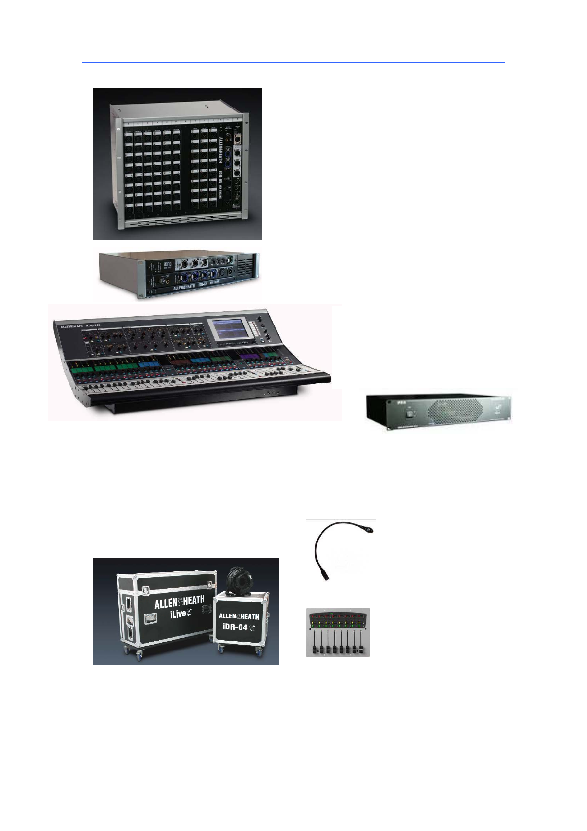
iLive System components
iDR10 MixRack The MixRack is the heart of
the digital audio processing system. It houses the
DSP mix engine together with control and audio
networking interfaces. The 64 input x 32 bus
architecture is fully configurable for mono/stereo
and type of mix. It is known as the iDR10 because it
has 10 card slots for fitting any combination of input
and output modules.
iDR0 MiniRack The MiniRack is similar to the
iDR10 MixRack except it does not have any card
slots for input or output modules. Instead it gets its
audio via the EtherSound network. It can be used
as the slave mix engine in an FOH/Monitor system
with digital mic split, or as a compact mixer with an
iLive Surface using the audio I/O in the back of the
Surface.
iLive Surface There are 4 sizes of control
surface available with up to 44 faders. These are
arranged in banks with 4 layers each. The surface has
a 4 slot card frame built in to load up to 4x 8 channel
input or output modules for local I/O.
CAT5 Cables iLive is shipped with a pair
of short CAT5 cables with locking Neutrik
connectors to connect the rack and surface,
one for audio, one for control. An optional 80m
(262’) drum of armoured CAT5 cable is
available from Allen & Heath. Two drums are
required for the typical system.
iLive Flightcases iLive systems can be
ordered with touring grade flightcases. These have
wheels with brakes. The MixRack case uses rubber
shock mounts to protect the rack and has front and
rear covers. The surface case is a three part design.
The surface may be operated while in its base.
iPS10 Backup PSU Rack mounted external
power supply to provide redundant backup for the
iLive Surface or iDR0 MiniRack.
LEDlamp 4-pin XLR gooseneck
LED lamp with built-in dimmer. Each
Surface has 3 lamp sockets except the
iLive-80 which has 2.
PL Series Remotes iLive is
designed to work with the Allen & Heath
PL Series remote controllers. Several
different models are available. Each
control and indicator can be
programmed from the Surface or using
the Editor software.
iLive System Manager PC
and MAC software for using a PC,
laptop or touch tablet to control the
iLive system or edit its settings off line.
TCP/IP Ethernet connection allows
wired or wireless control with or
without a Surface connected.
8 ALLEN&HEATH iLive Reference Guide AP6526 iss.3
Page 9
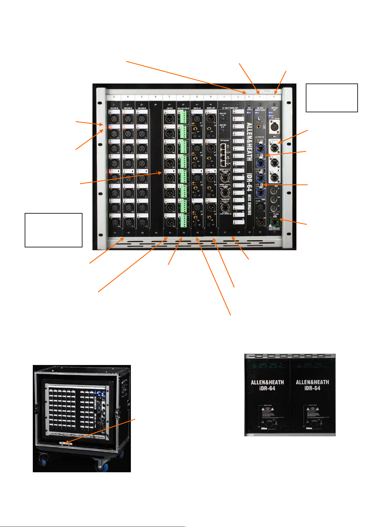
iDR10
MixRack
CHK indicators
Follow PAFL
selection
DSP ‘RackExtra’ module
The DSP mix engine, the heart
of the iLive mixing system.
64x32 mix architecture plus 8x
internal effects.
REMOTE AUDIO module
With system clock, headphones
and remote audio distribution. Fit
up to 2 audio network option
cards. EtherSound interface is
available here.
CPU module
Manages the MixRack
system and allows remote
control via Ethernet, MIDI
and PL-Anet. Also provides
a lamp socket.
System
modules
Slots K, L, M
Ethernet switch
3x network ports.
PP indicators
Detect phantom
power voltage
on XLR sockets.
MUTE indicators
Display output
mute status.
Audio modules
10 slots available.
Slots A to J
MIC/LINE IN module
8x mic preamps with remote
gain control.
LINE OUT module
8x balanced line out sockets.
Note: You can choose any combination of input, output and blank
modules to load into the 10 available slots. The format above shows all
the options available at the time of print and is not representative of a
typical user setup. The photo below shows a popular configuration with
48 mic inputs and 24 line outputs loaded. Further inputs and outputs
would typically be available at the rear of the surface.
DUAL MIC/LINE IN module
Connect 16x inputs on screw
terminal plugs. 8x mic
preamps each with remote
selection of A and B inputs.
ESA
EtherSound digital
snake. Surface
and break out/in
audio.
ESB
EtherSound digital
mic split, system
expansion, record.
PL-Anet
Connect to Allen &
Heath PL-Series
remote controllers.
MULTI DIGITAL OUT module
16x outputs in digital format. ADAT, Aviom,
Hearback, iDR Expander. Uses 2 slots.
DIGITAL OUT module
4x pairs of digital outputs simultaneously
available AES, SPDIF or OPTO.
DIGITAL IN module
4x pairs of digital inputs selectable
either AES, SPDIF or OPTO.
FLIGHT CASE
Touring grade case on
wheels. Shock mounted
rack. Front and rear
covers.
Module extractor tool
To pull out modules if you need
to reconfigure the module
format.
Note: Do not remove or plug
in modules while power is
applied. The iLive system is not
‘hot pluggable’.
ALLEN&HEATH iLive Reference Guide AP6526 iss.3 9
POWER SUPPLY module
Universal mains input. One
required. Fit second as redundant
supply backup.
Page 10
iLive
Surface
USB and VGA
Two USB ports available
in addition to the two
under the armrest at the
front. Option to connect
a monitor screen to the
VGA output to duplicate
the TouchScreen display.
Internal power supply
Universal mains voltage
power module with IEC
mains connector and
power on/off switch. Pclip for securing mains
cable.
Channel processing block
Analogue style layout with dedicated rotary controls,
switches and meters for the channel/mix preamp,
HPF, gate, PEQ, compressor and limiter/de-esser.
The controls are accessed using the strip SEL keys.
Select the input channel, mix master or FX return.
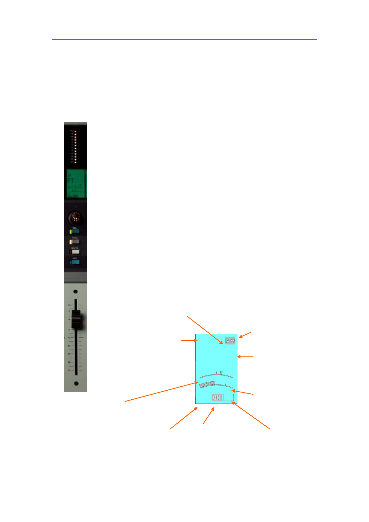
Control strip
Meter
Status LCD
Encoder
SEL key
PAFL
Mute
MIX key
Fader
Configure as:
Input channel
FX return
FX send
Group
Aux
Main mix
Matrix
DCA master
PAFL master
Fader Banks
Lamp connectors
Accept standard 12V
console lamps. We
recommend using the
Allen & Heath dimmable
LEDlamp.
CPU module
Manages the Surface system
and provides remote control
via Ethernet, MIDI and PLAnet. The built-in Ethernet
switch allows connection of
several devices to the
network, for example Surface
and a laptop.
Backup PSU input
For connection to the
Allen & Heath iPS10
redundant backup
power supply. DC and
temperature sense
REMOTE AUDIO module
Provides the digital audio
network interface to transport
the Surface audio to/from the
MixRack and other devices.
Not required if audio modules
are not fitted and analogue
connections are used for
Surface headphones and
talkback.
TouchScreen
Used for status display, system setup
and memory management. Also
provides an alternative graphical view
of the channel processing. The screen
may be tilted and dimmed.
Assign, Pre/Post, Rotary shift For current selected MIX Layer A,B,C,D select per bank
Audio connections
XLR sockets for surface Talkback mic
output, PAFL input and local monitor
output. Provides an analogue alternative
for connection to the MixRack when a
digital audio network option is not fitted.
Audio module options
4x card slots A, B, C and D to
fit optional audio input and
output modules. The
REMOTE AUDIO module is
required if audio modules are
fitted. Choose from the same
module types available for the
MixRack.
Soft keys
8x user assignable keys. Up
to V1.2 these are fixed as DCA
group 9-16 mutes, suitable for
use as mute group masters.
Talkback
Talk mic input and
assignment.
Engineer’s monitor
Headphones and
local monitor.
Solo-in-place
PAFL controls
Scene keys
Headphones, USB Freeze, Alt view, GEQ toggle Copy, Paste, Reset
iLive-80
20 faders (80 strips)
10 ALLEN&HEATH iLive Reference Guide AP6526 iss.3
iLive-112
28 faders (112 strips)
iLive-144
36 faders (144 strips)
iLive-176
44 faders (176 strips)
Page 11
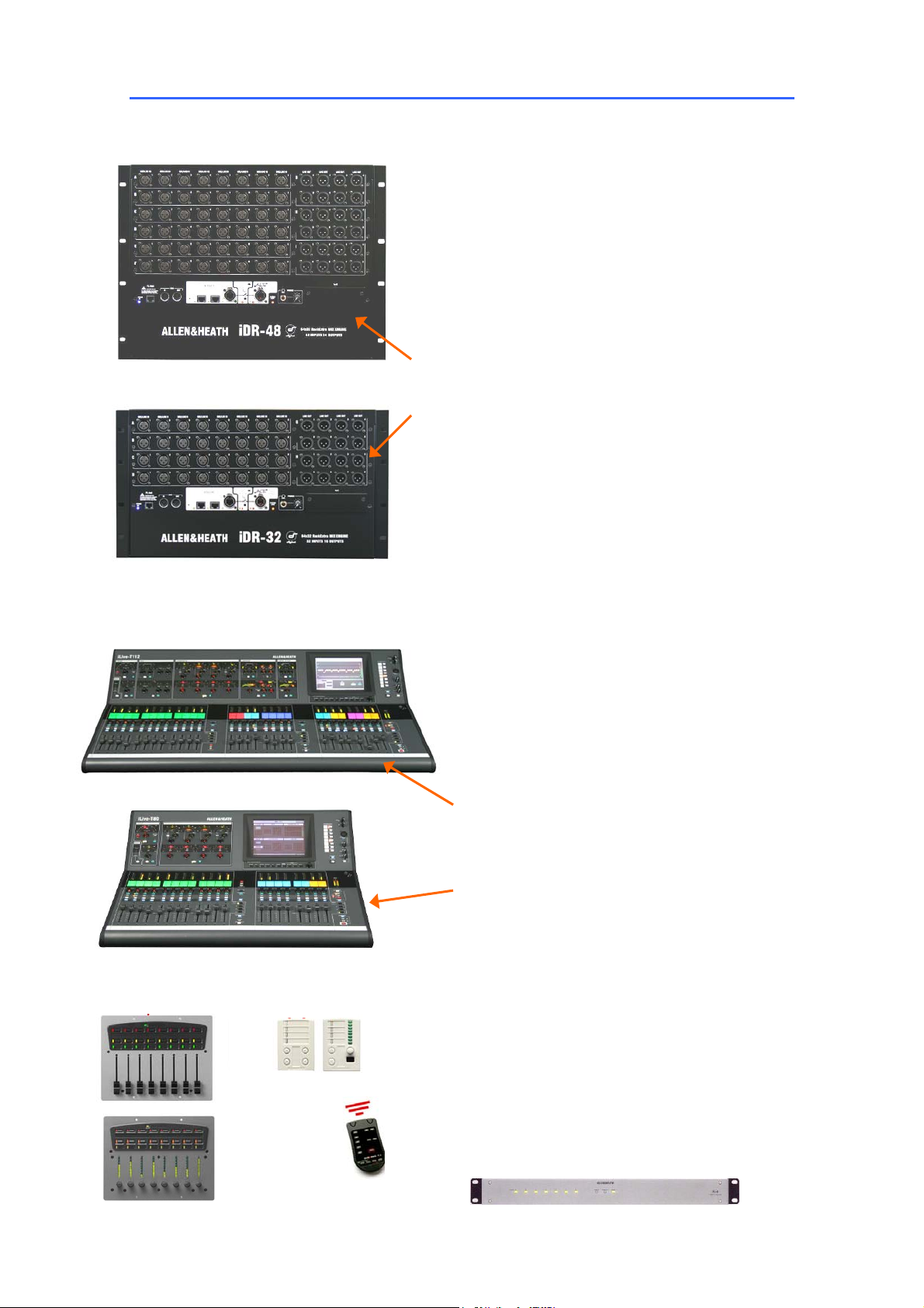
T Series System components
The T Series MixRack is the heart of the digital audio
processing system, housing the DSP mix engine together
with control and audio networking interfaces. The 64x32
architecture can be configured for mono/stereo and type of
mix (group, aux, mains, matrix). The system provides full
dynamics, EQ and delay processing for all inputs and
masters, 8 built-in ‘RackExtra’ effects and 16 DCA groups.
The 8 stereo FX returns add to the 64 input channels to allow
up to 72 sources to the mix. Unlike the standard iLive the
audio connections are fixed format rather than modular. The
racks differ only in the number of Mic/Line inputs and XLR
line outputs available.
iDR-48 the bigger rack: 48 Mic/Line inputs
24 XLR line outputs
iDR-32 the smaller rack: 32 Mic/Line inputs
16 XLR line outputs
The Surface is simply a network controller for the
MixRack. It has a built-in interface for local audio
which is transported to and from the MixRack via the
ACE connection along with the Ethernet control. Each
bank of faders has 4 layers providing a total of 80 or
112 control strips depending on Surface size. These
strips are freely assignable as inputs, mix masters or
DCAs in any combination. Both surfaces offer the
same control, the only difference being that the
smaller 80 does not provide the rotary control section
for the dynamics. These are accessed via the
TouchScreen on this model.
iLive-T112 the bigger surface:
28 faders = 112 strips
16 local line in = 8 TRS, 4 RCA, 2 SPDIF (digital)
14 local out = 8 TRS, 2 RCA, 1 SPDIF, Monitor
iLive-T80 the smaller surface:
20 faders = 80 strips
8 local line in = 4 TRS, 2 RCA, 1 SPDIF
10 local out = 4 TRS, 2 RCA, 1 SPDIF, Monitor
PL-3 PL-4
PL-10
Faders
PL-6
Encoders
ALLEN&HEATH iLive Reference Guide AP6526 iss.3 11
PL-5
PL-9
Hub
PL Series controllers A range of remote controllers
is available with assignable switches, LEDs, encoders
and faders. These connect to the MixRack via the PLAnet serial port using CAT5 cable and can be
configured using the Surface or laptop. The PL-9 hub
is allows star point instead of daisy chain connection.
More information on the PL Series is available on the
Allen & Heath web site.
Page 12
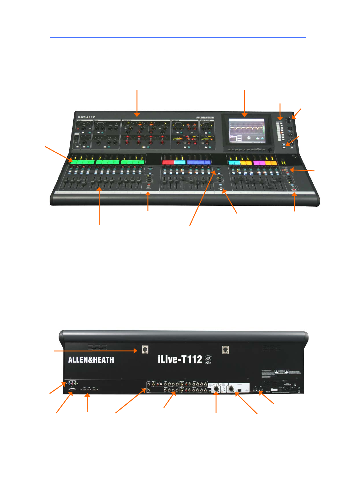
T Series Control layout
Channel Processing Strip Analogue style control
section with dedicated rotary controls, switches and
meters for the channel or mix preamp, HPF, gate, PEQ,
compressor and limiter/de-esser. Press the strip SEL
key to access the processing of the channel or master
assigned to it. The controls illuminate when they are
available.
Virtual write-on strip
Name and colour
TouchScreen For status display,
system setup and memory management.
To see an alternative graphical view of
the processing for the channel or master
currently selected make sure none of the
keys below the screen is selected.
Soft Keys 8 user assignable keys
Dimmer
Talkback. Hold
down TB ASSIGN
and press the
master MIX keys
to assign.
PAFL
monitor
and SIP
Copy/Paste/Reset edit keys
Fader Banks Independent groups
of fader strips with 4 layers each.
Provides control of the Input
channel, FX return, Mix master or
DCA assigned to it.
SEL opens the channel processing
for the selected strip.
MIX presents the sends for the
selected strip on faders (or
encoders) and assignments and
pre/post settings in the strip LCD
windows.
Lamp
sockets
ASSIGN and PRE/POST access
keys for the selected mix.
Hold down ASSIGN and press
strip MIX keys to toggle the
assignments on or off.
Hold down PRE/POST and
press strip SEL keys to toggle
pre or post fade.
Hold down ROTARY SHIFT to
access the second encoder
function if it has one.
Hold down ALT VIEW to
view the channel or
socket numbers in place
of the name in the LCD
windows.
GEQ FADER FLIP to
present the GEQ across
the faders.
FREEZE IN LAYERS to
keep a channel visible
across all layers. Hold
down and press strip
MIX keys.
Scene recall keys.
These can be
disabled.
SCENE SAFES to
prevent selected
channels being
overwritten by the
memories. Hold
down SAFES and
press MIX keys to
toggle on or off.
For future
use…
VGA port for
external monitor
(same view as
TouchScreen).
12 ALLEN&HEATH iLive Reference Guide AP6526 iss.3
2x USB
ports.
Plug in
USB key
here.
Local
PAFL
monitor
output
Assignable local
audio inputs and
outputs.
Rows A and C are
inputs, B and D are
outputs.
Digital is SPDIF.
Audio/control link
between Surface and
MixRack.
ACE (audio and
control over Ethernet)
CAT5 cable up to
120m (400 feet)
MIDI in and out
Additional Ethernet ports
for connecting laptops
and wireless router.
Page 13
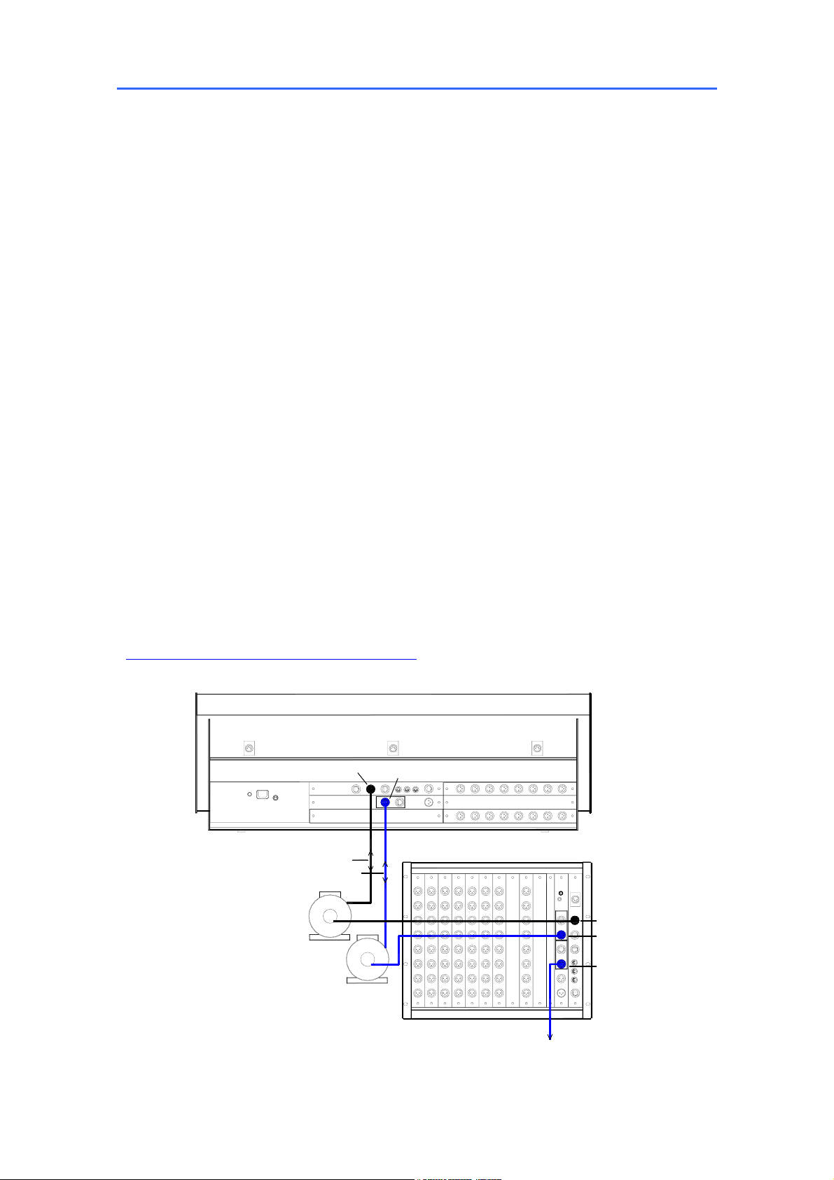
Connecting the iLive MixRack and Surface
The iLive has two main system connections between the Surface and MixRack, both using CAT5 cables.
NETWORK is the control interface to the MixRack. ESA primarily connects audio to and from the Surface
and other EtherSound equipped break in/out devices. The optional ESB port can be used to connect
audio between systems such as FOH/Monitor, broadcast or recording. iLive systems are shipped with 1.8
metre UTP CAT5 cables fitted with EtherCon locking connectors as standard. Allen & Heath can supply
an 80 meter drum of approved cable if the Surface is located remote from the MixRack. Two of these are
required to connect control and audio between the MixRack and the Surface. One is required to connect
audio between the MixRack and another remote rack.
Ethernet (control network) CAT5 cable
A 3 port Ethernet switch is built into the CPU module allowing connection of more than one control
device, for example a Surface and a laptop. Cables up to 100 metres (330 feet) may be used. Plug the
CAT5 cable into any NETWORK port. Standard Ethernet hardware may be used to extend or route this
connection if required.
Note: Plug only one CAT5 cable to connect the NETWORK between the MixRack and Surface.
Plug this into any one of the three network ports available. Do not connect a second cable for
redundancy. Third party systems are available to extend the connection or provide dual redundancy.
EtherSound (audio network) CAT5 cable
Plug the MixRack ESA OUT to the Surface ESA IN to connect the PAFL, talkback and rear panel
input/output signals (ES channels 1 to 32) to and from the Surface. Plug the Surface ESA OUT to external
break in/out device ES IN to route signals to and from further locations if required (ES channels 33 to 62).
For information on using the optional ESB network refer to the application diagrams later in this user
guide.
Note: Connect only one EtherSound cable between two devices. Do not connect both IN to OUT
and OUT to IN. The terminology ‘IN’ and ‘OUT’ refers to the clock master and not direction of audio.
Each EtherSound cable carries 64 channels of audio in both directions.
Note: The EtherSound standard is maintained and licensed by Digigram who recommend that only
the cable types and network components tested and approved for EtherSound are used. This is
most important to ensure reliability when using longer cable lengths approaching the 100 metre (330 feet)
maximum. For further information on compatibility please refer to the EtherSound web site:
www.ethersound.com/technology/compatibility.php
.
NETWORK
CPU
RAB
CONTROL (ETHERNET)
AUDIO (ETHERSOUND)
ESA IN
Connect RACK ESA OUT to SURFACE ESA IN
NETWORK
ESA OUT
ESB OUT
ETHERSOUND MIC SPLIT / SYSTEM EXPAND
ALLEN&HEATH iLive Reference Guide AP6526 iss.3 13
Page 14
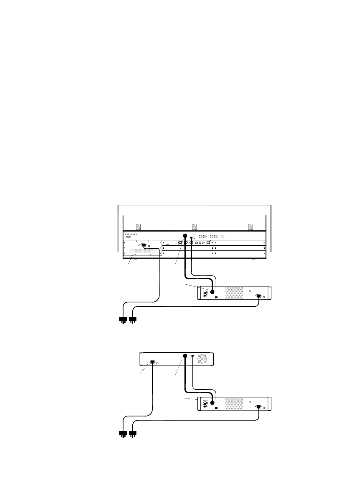
An IEC mains power cord with moulded plug suitable for your territory is provided for
each power supply module within the system. The iLive system uses universal voltage
power supplies that accept world wide mains sources from 100 to 240V.AC 47 to 63Hz.
Make sure the IEC plugs are pressed fully into their panel sockets and the cables are
clipped into the retaining clips to protect them from accidental disconnection.
Note: To ensure operator safety, connect only to an approved and properly
grounded mains source. Do not remove the ground connection in the mains cord.
Note: Read and understand the warnings in the safety sheet supplied with the
equipment and printed on the power unit panels.
Note: It is good practice to connect both the MixRack and the Surface to the same
mains power ring or feed, and to use a UPS (uninterruptible power supply) as a backup
in critical applications where there is any risk of mains or generator power being
interrupted.
MAINS FUSE - In the event of a fuse failure replace only with the correct type and
rating as indicated on the rear panel. If the replacement fuse fails again, switch off and
refer to your Allen & Heath service agent.
ON/OFF switch - Press to switch mains power on or off. Blue status LED indicators
light on the power supplies and modules to indicate that power is present and correct.
iPS10 backup power supply - The optional iPS10 rack mounted power supply unit
may be connected to the Surface or iDR0 MiniRack as a redundant backup if required.
The iDR10 MixRack already has provision for a second backup supply module.
iLIVE SURFACE
INTERNAL PSU
IEC MAINS CABLES
Mains power 100 - 240V AC
MAINS
INTERNAL PSU
Female plug
DC CABLE
10way
Male plug
iDR0 MINIRACK
Female plug
DC CABLE
10way
Male plug
TEMPERATURE MONITOR CABLE
CAT5
iPS10 BACKUP PSU
MAINS
TEMPERATURE MONITOR CABLE
CAT5
iPS10 BACKUP PSU
MAINS
IEC MAINS CABLES
Mains power 100 - 240V AC
14 ALLEN&HEATH iLive Reference Guide AP6526 iss.3
Page 15
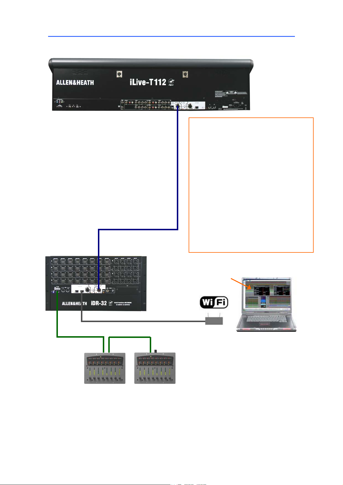
Connecting the T Series MixRack and Surface
The Control Surface
Connect Surface to MixRack
Plug a CAT5 cable up to 120m (400 feet)
between the Surface and MixRack ACE ports.
An 80m drum of suitable cable is available from
Allen & Heath (part number AH7000).
Note: You only need one connection between
the Surface and MixRack. The control network
data is transported with the audio via the single
cable ACE link. You do not need a second
cable for the network link.
ACE
The Mixer
Network settings
iLive-T communicates over a TCP/IP network.
There are 3 main components – the MixRack,
Surface and TouchScreen (built into the surface).
These and any other network devices such as a
wireless router and laptop need compatible
network addresses. Factory defaults are:
MixRack 192.168.1.1 Sub mask 255.255.255.0
Surface 192.168.1.2
TouchScreen 192168.1.3
We recommend you set:
Laptop 192.168.1.10 Sub mask 255.255.255.0
Router 192.168.1.245
If the addresses or unit names have been
changed and your system fails to connect, or you
need to reset the settings, refer to the
Troubleshooting page in the TouchScreen HELP.
NETWORK
PL-ANET
IN OUT IN
Termination
Adding PL Series controllers
Use CAT5 cable to connect the MixRack PL-Anet port to
the PL device IN socket. Daisy chain OUT to the next
unit, or use a PL-9 hub for star connection. Make sure
the terminator provided is plugged into OUT of the last
device in the chain. Once connected, the PL controls
need to be configured. Settings can be saved as library
items.
iLive Editor software.
Download from
www.allen-heath.com
Adding laptop control
Check that your laptop meets the system
requirements for running the iLive Editor
software. Read the Release Notes that
come with the software.
Make sure the laptop and wireless router
have network addresses compatible with
the iLive system.
Plug your laptop or wireless router network
connection into any one of the NETWORK
ports at the Surface or MixRack.
ALLEN&HEATH iLive Reference Guide AP6526 iss.3 15
Page 16
Booting up the system
Turning on the system
Note: Always turn the MixRack on first, then the iLive Surface.
The iLive system remembers its last settings on power up.
1. First, plug in the mains and CAT5 cables.
2. Next, switch on the MixRack power.
3. Then switch on the Surface power.
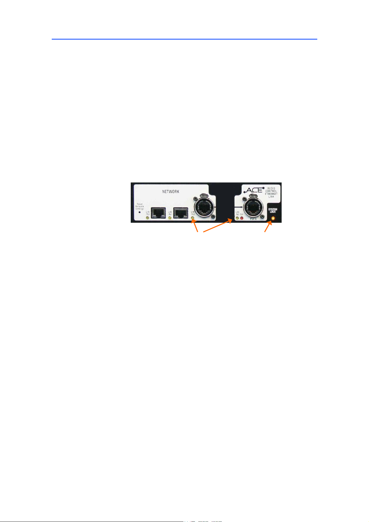
While searching for the network connection between the MixRack and Surface after
power up, the NETWORK Lnk/Act indicators flash at a slow rate for a few seconds.
Once connection is successfully made the indicators flash at a steady fast rate. If the
EtherSound option is fitted, their RX and TX indicators should flash at a steady fast rate
soon after boot up.
The MixRack and Surface audio outputs are isolated from the connected equipment
during boot up using protection relays to prevent power up thumps. The connector
MUTE indicators light while the outputs are isolated. After around 15 seconds the
relays switch in and audio is presented to the outputs with the settings as they were the
last time the system was powered down.
The yellow Lnk/Act LEDs for connected sockets
flash at a steady rate once the link is established.
If one or more pulse at a slow rate or the red Err
LED remains lit then check that the cables are
correctly plugged in and are not faulty.
At the MixRack: Indicates that the
audio is sync locked to the
selected clock source.
At the Surface: Indicates that the
surface audio is sync locked to
the MixRack.
Boot up time
MixRack It takes around 15 seconds for the DSP to start passing audio with the same
settings current at last power down.
Surface In just over 1 minute the strip LCD displays turn on and the Surface is ready
to take control of the mix. If a password is required for log in then surface operation is
not available until after the TouchScreen has finished booting.
TouchScreen It takes a little longer for the TouchScreen to complete its boot up
process during which time you will see its BIOS load the LINUX operating system and
then the iLive application. In around 2 minutes the screen is ready and the system fully
booted.
Note: If your system fails to connect please refer the section on Network Settings.
Turning off the system
To shut down the system, first power down the TouchScreen using the button in the
UTILITY / Configuration screen. Then switch off both units at their respective power
switches. The system shuts down safely after the current settings have been stored to a
battery backed memory.
Note: Make sure you archive your settings regularly to reduce the risk of losing
or overwriting your data. If power is lost while moving data to or from a USB memory
stick on the console, there is a possibility that your files may become corrupted. It is
good practice to use a UPS (uninterruptible power supply) for mains backup during
important shows.
16 ALLEN&HEATH iLive Reference Guide AP6526 iss.3
Page 17
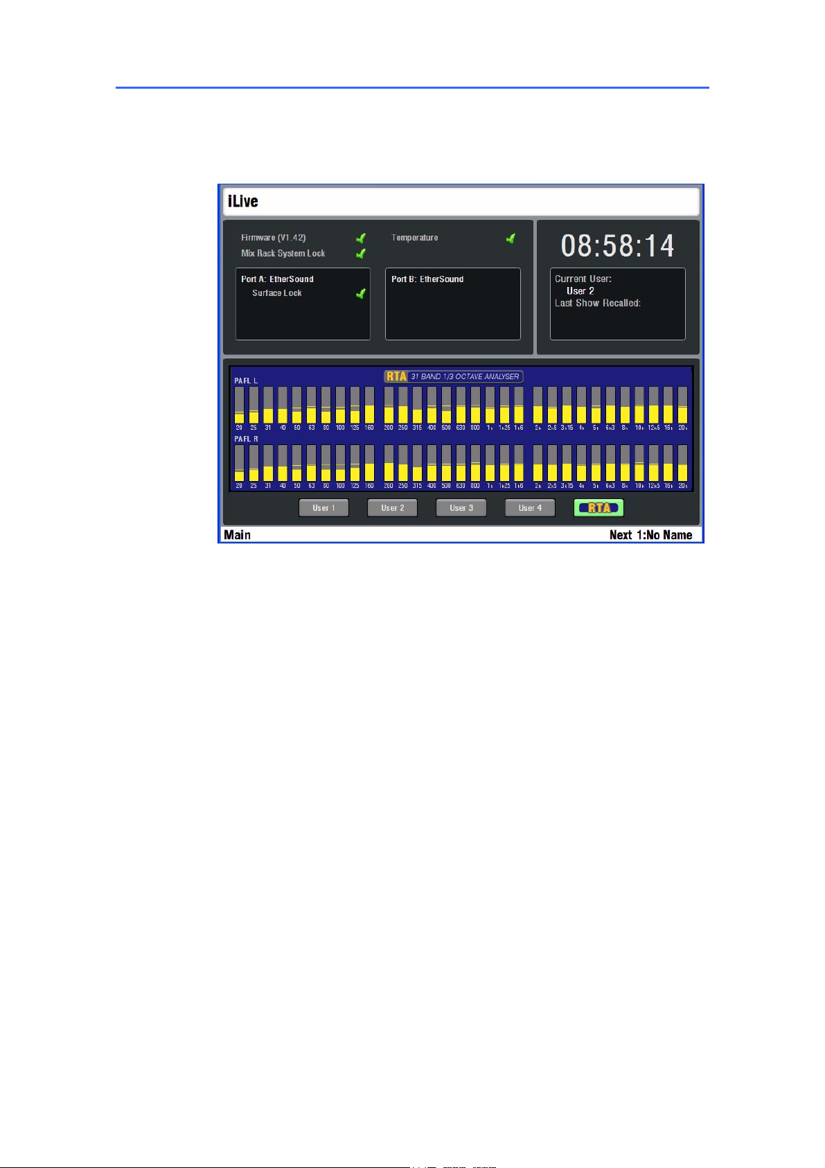
The Status screen
The TouchScreen ‘Status’ page is displayed when the fader strip SEL keys and the keys below the screen
are all off. It is the default view when nothing is selected. It provides display of a real time clock, system
status and access to the user assignable custom meters and the RTA display.
For normal operation green ticks should be present. A red cross means a problem has
been detected and should be checked.
Firmware Displays the current firmware version loaded. A green tick means the
system firmware is operating correctly. A red cross warns that an error has been
detected and has been logged in the system Event Logs. A yellow triangle also
displays in the lower toolbar to alert you if you are in another page. Go to the UTILITY /
Diagnostics / Event Logs page to view the error. The Event Log can be copied to USB
key to be reported to Allen & Heath if required. After viewing the error log the green tick
is restored. For the latest version of iLive firmware please refer to the Allen & Heath web
site.
Temperature The iLive monitors its temperature at several places within the
MixRack, Surface and power supplies. If it exceeds a maximum threshold then a red
cross displays to warn you. Go to the UTILITY / Diagnostics / Temperature page to
view the current temperatures.
MixRack System Lock A green tick displays that the MixRack is sync locked to
the selected audio clock source. If a red cross appears then check the Audio Clock
Source setting in the MIXRACK / Mixer Pref / Audio Sync Networks page.
Port A, Port B These boxes display status information for the digital audio network
options fitted, for example EtherSound or ACE. A green tick next to Surface Lock
indicates that the Surface audio is sync locked to the MixRack.
ALLEN&HEATH iLive Reference Guide AP6526 iss.3 17
Page 18
Clock Displays the TouchScreen CPU real time clock. The time may be changed
from the UTILITY / Configuration / Date Time page.
Current User The current User name is displayed here. To log in as a different
user go to the UTILITY / Change User page. Up to 8 User Profiles may be set by the
Administrator using the UTILITY / Configuration / Edit User Profiles page.
Last Show Recalled Displays the name of the last Show memory recalled. To
recall a different show go to the UTILITY / Configuration / Show Manager page.
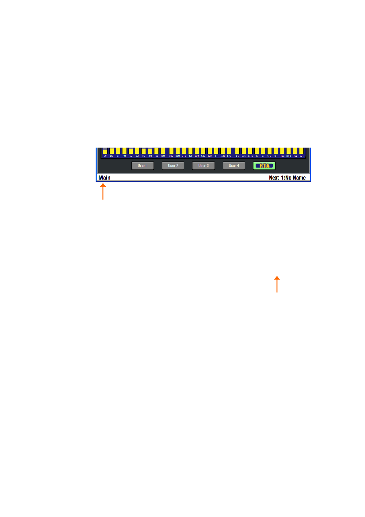
Lower Status bar
Current Mix The left of this toolbar always displays the active fader strip mix type
and number as currently selected using the MIX keys. For example ‘Input 9’ indicates
that the input channel 9 MIX key is selected and the master strips display the
assignments and sends from that input. ‘Mono Aux 1’ indicates that the mono Aux 1
master strip MIX key is selected and the inputs strips display the assignments and
levels to that master. Deselecting a MIX key returns the strips to the Main mix if one is
configured. This is the recommended default mode for FOH mixing. ‘Main’ displays on
the toolbar to indicate you are in the default mix. If there is no main mix, for example a
monitor mix configuration, then the left of the toolbar remains blank when the MIX key is
deselected.
Current and Next Scene The right of the lower toolbar displays the name and
number of the last Scene memory recalled during the session, and the name and
number of the Scene currently highlighted in the SCENES page. The highlighted Scene
is the next that would be recalled when you press the GO key to the right of the faders,
for example for use as scene recall during a theatre production. To enable these keys
go to the TouchScreen SURFACE SETUP / Preferences page.
Note: To avoid accidentally overwriting your current settings make sure the
Surface Scene Keys are disabled if you are not using them.
Status information The lower toolbar also displays useful information while
operating the console. For example, it shows you what parameters are held in the copy
buffer while the COPY or PASTE keys are held down.
USB symbol Displays when the system recognises a USB memory key plugged
into one of its USB ports.
Yellow warning triangle Displays when a system error has been detected.
Return to the Status page for further information.
18 ALLEN&HEATH iLive Reference Guide AP6526 iss.3
Page 19
Surface basics – The TouchScreen
The TouchScreen provides a graphical display of the parameters and assignments, allows configuration
of the system, and management of the memories and data. Unlike many other digital consoles it is not
essential to the live mixing operation. iLive avoids fiddly screen and menu based mixing by providing a
large analogue style channel processing interface with dedicated rotary controls, switches and indicators.
Although the screen can give you an alternative graphical view of these parameters, its main function is
for system setup and data management.
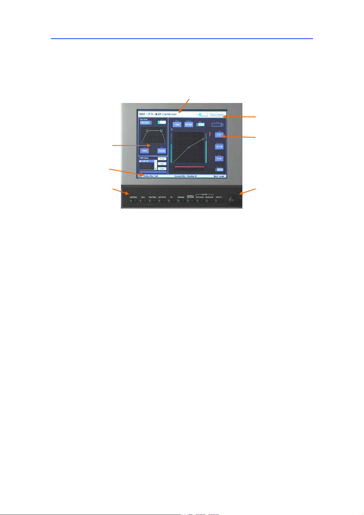
Work area
Status bar
Title bar
Return button
Data entry box
Data entry encoder Screen keys
Title bar Displays the name and information about the currently selected screen or
channel.
Return button Touch this button to return to the previous or top level page. The
TouchScreen remembers the last page opened for each screen selected. For example,
if the Compressor was the last item viewed in the channel processing screen, it will
open in the Compressor view again when another channel is selected. Touch Return to
return to the top level ‘thumbnail’ view.
Status bar Displays various status information, the currently selected mix type and
number, and the previous and next scene recall.
Data entry encoder Touch a data display box to select a parameter to adjust.
The box turns orange to show it is selected. The data entry rotary encoder lights
orange to show it is available for updating the value. Change the highlighted parameter
value by scrolling up or down through its range.
Screen keys Press one of these keys to change the screen function. The green
indicator lights to show which is active. With none of these selected the screen shows
either the Status page (no channel selected) or a channel processing view (channel
selected using its green SEL key).
Note: To display the status or channel processing pages make sure the screen
keys are turned off. Selecting one of these keys overrides the status or selected
channel view with the function indicated above the key.
Note: Do not leave the screen in NAME&COLOUR or SURFACE SETUP mode as
these change the strip SEL key function. These modes are used during system
configuration.
ALLEN&HEATH iLive Reference Guide AP6526 iss.3 19
Page 20
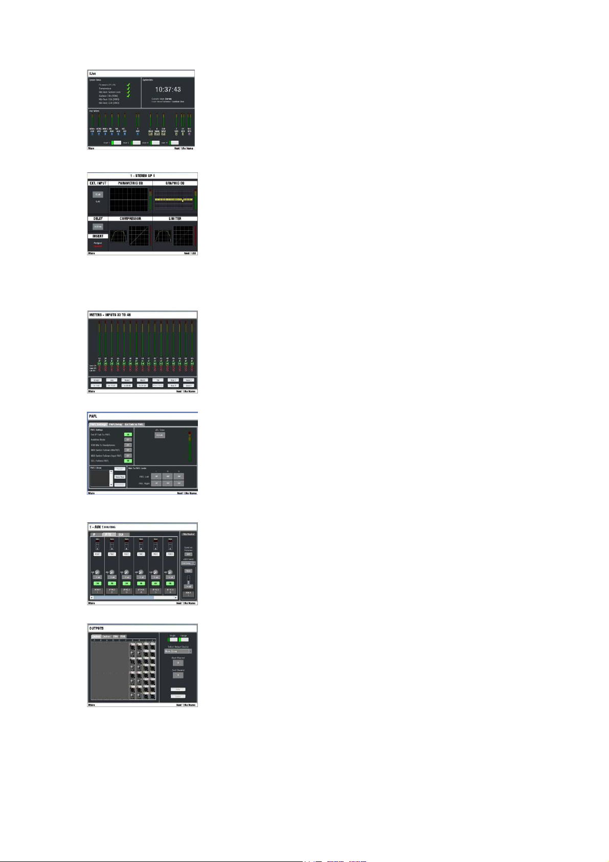
All screen keys turned off – STATUS With all the screen
keys and strip SEL keys turned off the TouchScreen displays the
Status page. This shows system status including firmware,
temperature, audio system lock and digital audio network status. A
red cross means a problem is detected. The page also displays the
time, current user and last Scene recalled name. The lower part of
the screen can be used to select one of the four custom user meter
views or the RTA display.
All screen keys turned off – Strip SEL selected If you
press a strip SEL key while the screen keys are turned off then the
TouchScreen displays the processing view for that channel. This can
provide additional graphical information for the parameters shown on
the controls to the left of the screen, for example an EQ or dynamics
curve. Some channel and mix parameters are only available via the
screen, for example delay, insert assignment, name and colour.
Screen key selected:
METERS Select from several pages of audio meters showing
input channels, effects and mix masters. Includes 4x user custom
meter views. You can name each view and configure any
combination of up to 16 meters and spaces per view. The screen
also lets you view the RTA display. The custom views and RTA can
also be selected from the default Status page.
PAFL Set user preferences for the PAFL engineer’s monitoring
system. Choose between additive and auto-cancelling operating
mode, adjust the AFL trim to avoid big level differences between PFL
and AFL, set main mix to monitor level when no PAFL is selected, and
choose to link the SEL and/or MIX keys with PAFL key presses. You
can turn on and select the External Input to PAFL source for reverse
talkback, and set delay to time align the monitor to the acoustic
sound from the stage.
ROUTING This screen displays the routing and DCA
assignments, direct out trim, send levels and preferences for the
channel currently selected using the SEL key. For the Aux masters it
lets you select the channel send source and choose to have the
sends on faders or rotaries. The screen can provide an alternative to
adjusting the mix sends and assignments on the fader strips using the
MIX keys.
OUTPUTS Map signals to the physical sockets and audio network
channels. Touch tabs let you select the MixRack, Surface, Port A and
B patch bays. Assign single or a range of sockets from a choice of
mixes, direct outs, insert sends and other sources.
20 ALLEN&HEATH iLive Reference Guide AP6526 iss.3
Page 21
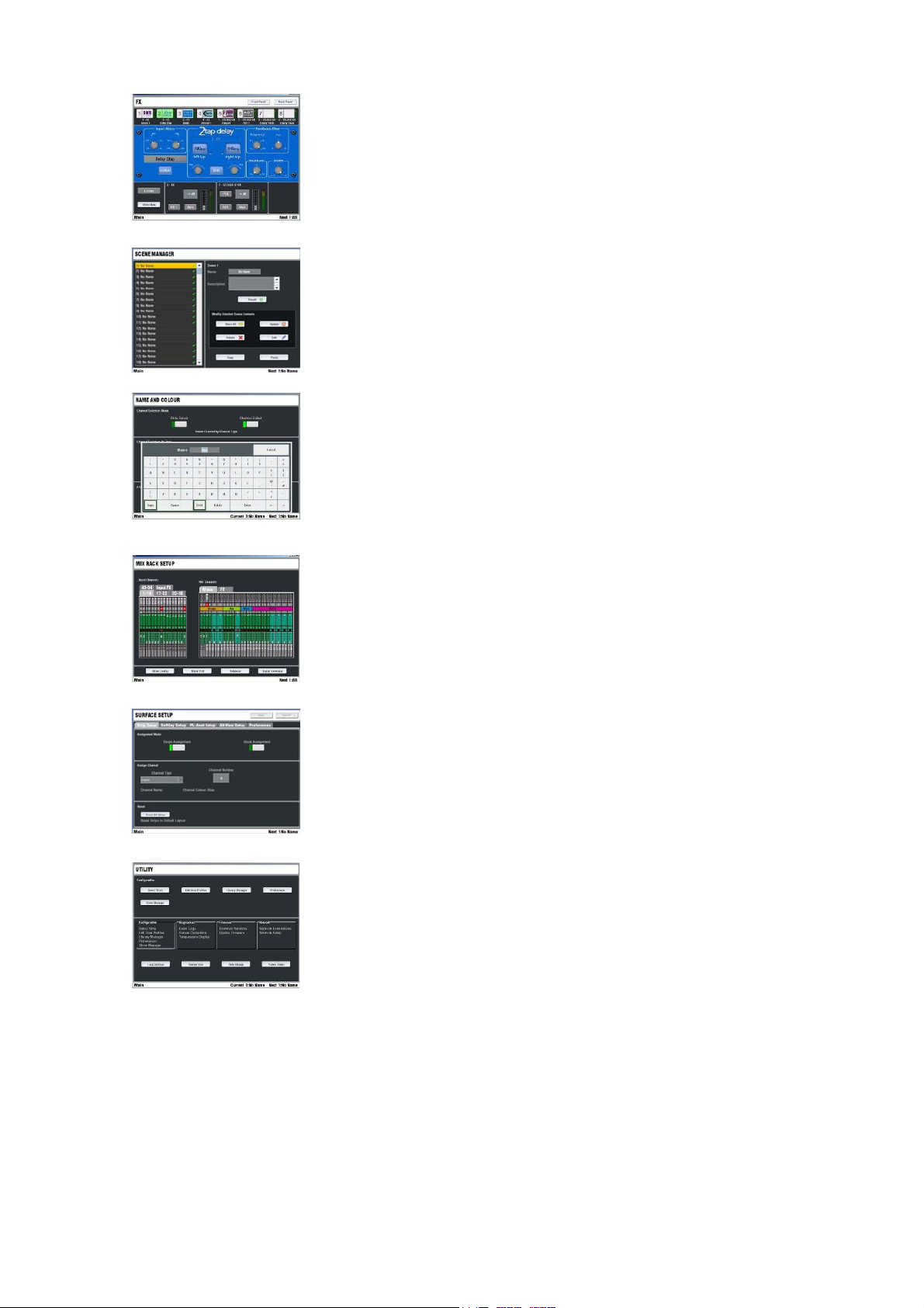
FX Access the FX rack. Provides 8 virtual ‘rack positions’ for
loading your choice of processing from a library of effects devices
including reverbs, delays, modulators and more. A Front Panel view
presents a familiar control interface for parameter data entry. A Rear
Panel view lets you ‘patch’ the device into the signal path either as a
‘mix>return’ or ‘insert’. Choose the input to the device from a mix or
direct output, and its output to an FX (short) return or full channel.
SCENES Access the Scene memories for storing and recalling all
or selected processing, mix and setup parameters. Scenes can be
named, copied and edited. These are typically used for theatre show
cues, multiple band music festival recall, event changes and so on.
Console parameters may be added to a Scene, or the existing
contents updated with the current console settings.
NAME&COLOUR Enters a setup mode to use the strip SEL
keys to choose the input, mix and DCA master colours and enter 5
character names for each. Choose from a swatch of 6 colours plus
off (no colour) for a single or range of channels. The colour is
displayed on the Surface strip LCDs. You can also store up to 48
custom names in a ‘Quick Menu’ for instant recall of commonly used
names. Note that name and colour may also be set individually for
the inputs and mixes from their normal processing views.
MIXRACK SETUP View and configure the MixRack architecture.
Configure the 32 mix buses from a choice of mono/stereo Group,
Aux, Main and Matrix mix types. Choose from a list of 9 main mix
types such as none, M, LR, LCR, LR+Sub and more. Other pages let
you configure the digital audio networks, Direct Out source, Talkback
source, channel ganging and provide access to the onboard signal
generator.
SURFACE SETUP Enters a setup mode to use the strip SEL
keys to assign the Surface strips as input channels, mix masters, DCA
masters and more in any combination. You can assign single strips
or a range of strips within a fader bank. Other pages let you
configure the SoftKey functions, PL devices, the ALT VIEW key, and
Surface preferences.
UTILITY Manage the Show and Library memories and User
Profiles here. Factory default ‘Template’ Show memories let you load
from a choice of standard configuration to give you a quick starting
point. Save your customised configurations as User Shows. You can
access the USB port for file transfer and archiving as well as updating
the system with the latest firmware available from the Allen & Heath
web site. This screen also provides access to many additional
facilities including TCP/IP network setup, system diagnostics,
changing user, locking the surface, reading the onboard Help manual
and powering down the TouchScreen before switching the system off.
ALLEN&HEATH iLive Reference Guide AP6526 iss.3 21
Page 22
Surface basics - Fader control strip
A
The Fader Control Strip is the primary user interface for mixing with iLive. It provides a familiar analogue
console layout and is arranged in banks across the surface. The smallest iLive-80 surface has two banks
of faders (12 and 8), the larger models have three (up to 24, 12 and 8). Each fader bank has 4 layers A,
B, C, D providing the largest surface with 176 strips, and even the smallest with as much as 80. Any
input, mix or DCA can be mapped to any strip on any layer. You can map these to multiple strips letting
you arrange different combinations of channels across the layers, or the same across several layers and
banks. With thoughtful choice of colour and strip assignment you can create an intuitive console layout
that suits the way you want to work. You can save this layout in the Scene and Show memories for future
recall or transfer to other iLive systems.
Meter Displays audio signal activity for the channel or mix master. Input
channel metering is post-processing, pre-fader. Mix master metering is postfader, post-mute so you can check the signal present at the output. The red
PK! indicator lights to warn that the signal is within 5dB of clipping. It is multipoint sensing which means it detects peak activity at several points in the
signal chain and can therefore keep a check on signal activity throughout the
channel path.
Note: If the top red LED lights before the rest of the meter, or while the
channel fader is down, this means that the signal is peaking earlier in the
channel path. Press SEL to open up the channel processing and check
signal activity.
Note: iLive meters are digital absolute peak response meters. This
ensures you keep control and avoid digital clipping of signals including those
with very fast dynamics. It does mean the iLive meters may read hotter than
those on other consoles you are used to.
Strip LCD The LCD strip spans the fader bank and is the digital equivalent
of the traditional console write-on strip. It displays information about the
channel assigned to the control strip – Channel type, name or number, rotary
encoder function and setting, channel status, and information about the
current mix. A 6 colour backlight displays the user assigned channel colour.
The LCD switches to display the related EQ frequency while in GEQ on faders
mode.
DCA status
On = The channel is assigned to one or more DCA groups.
Flashing = Channel is muted by DCA groups.
Strip type
Mono or stereo
IP = Input channel
IP FX = FX ‘short’ return
GP = Group master
AUX = Aux send master
MAIN = Main mix
MTX = Matrix master
DCA = DCA master
WDG = Wedge master
IEM = IEM master
Rotary setting
Normal = PAN (fader mix), LEV (rotary mix)
Shifted = LEV, PAN, BLEND, SUB or M
SAFE status
STEREO
IP
DCA
NAME
PAN
LR
LEV
CH
FADER
AUX
PRE
Normal mode = SCENE safe
Solo-in-place mode = SIP safe
Name
5 character, user defined name.
Shows DSP channel number,
socket position or dB value in
LT VIEW
Current MIX status
Indicates currently selected
fader or rotary mix.
GP, FX, AUX, MTX
CH FADER
Turns on when the strip fader is
the channel or master fader.
Turns off when the fader is a
send level control.
22 ALLEN&HEATH iLive Reference Guide AP6526 iss.3
ON
The channel is assigned
to the current mix or
DCA.
PRE
The channel AUX or MTX
send is pre-fader. Off =
post-fader.
Page 23
PAFL
ACTIVE
OUTPUT AFL
INPUT AFL
CLEAR ALL
SEL
PAFL
MUTE
MIXMIX
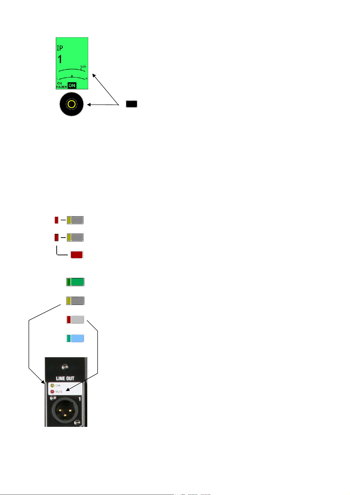
Rotary encoder This control lights up when it has a function assigned. It
is used as a send level, PAN or image control depending on the type of mix
currently selected with the MIX key and whether it is a fader or rotary mix. If
the mix has two image functions, for example, PAN and SUB level when
configured as an LRSub main mix, or Aux SEND and PAN for a stereo Aux mix
on rotaries, then the LCD displays two dials, one for each function. To access
the upper dial function hold down the ROTARY SHIFT key while turning the
encoder.
ROTARY SHIFT
Normal and shifted rotary functions
SEL key This green key provides access to the channel processing. The
current settings for the selected channel are displayed in the large processing
control section above the strips. Associated information is also displayed in
the TouchScreen if none or the ROUTING screen key is selected. The
controls illuminate when they are active. Press another SEL key to access the
processing for a different channel, or press the key again to turn it off. With no
processing selected the control section turns off.
Note: The SEL keys do not access the channel processing if the console
is in a setup mode (NAME&COLOUR, MIXRACK or SURFACE SETUP). In
this case they are used to select strips for the related setup mode. To avoid
operator confusion do not leave the screen in one of these setup modes.
PAFL key Selects either the PFL (pre-fade listen) or AFL (after-fade listen)
signal to the engineer’s headphones / local monitor depending on the setting
of the AFL keys below the PAFL meters. Press PAFL keys to toggle them on or
off, or use the CLEAR ALL key in the master section to turn off the current
selection. The associated yellow CHK indicators light on the iDR10 MixRack
and iLive Surface audio modules while PAFL is active. The T Series does not
provide these indicators.
Operating preferences may be set using the PAFL screen:
Auto-cancel or additive mode
AFL level trim
Link SEL key to PAFL key
Link MIX key to PAFL key (separate options for Input and Mix)
MUTE key Turns off the channel, mix or DCA as it would on a traditional
analogue console. It mutes the pre and post fade signals. The associated red
MUTE indicators light on the audio output modules in the MixRack or Surface
while mute is active.
Note: As standard, MUTE always affects the whole channel. It does not
provide individual send muting while in AUX or MTX mix mode. The ability
to quickly mute the whole channel while in any mix mode is important for live
sound mixing. To switch individual Aux or Mtx sends on or off use the ASSIGN
function.
ALLEN&HEATH iLive Reference Guide AP6526 iss.3 23
Page 24
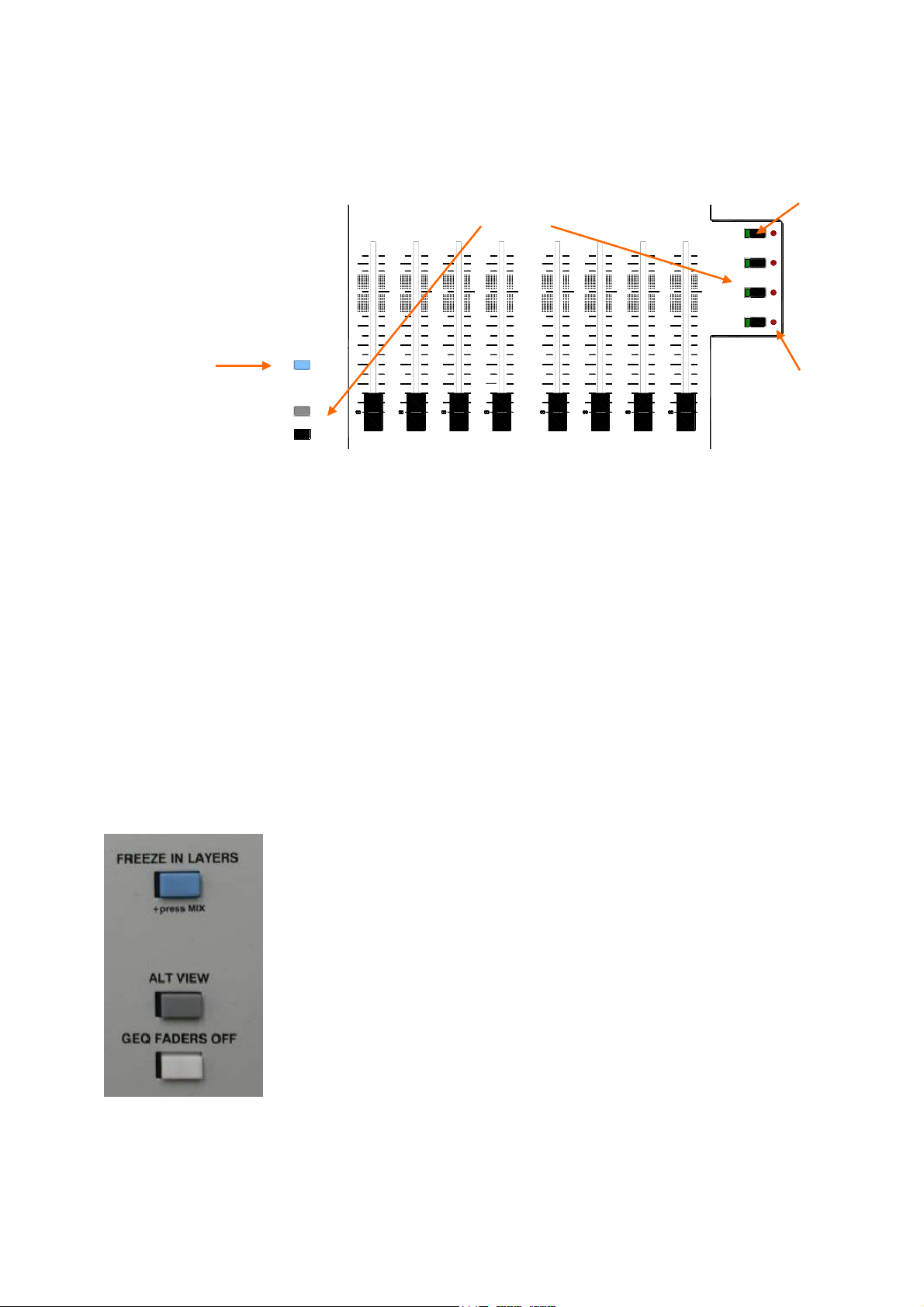
Fader The fader is motorised and automatically changes position when you
select different fader layers or change the mix using the MIX keys. They also
change to show the mix master GEQ (graphic EQ) settings when in GEQ
FADER FLIP mode.
Freeze
FREEZE IN LAYERS
ALT VIEW
GEQ FADERS OFF
Change fader function
10
10
10
10
10
10
5
5
0
0
5
5
10
10
20
20
30
30
40
40
10
5
5
0
0
5
5
10
10
20
20
30
30
40
40
5
5
0
0
5
5
10
10
20
20
30
30
40
40
10
5
5
0
0
5
5
10
10
20
20
30
30
40
40
BANK
3
A
B
C
D
Working with Layers Each bank of faders has 4 layers. Therefore a
bank with 8 faders can control up to 32 channels or masters. The largest
surface with 44 faders can control up to 176 of these, while the smallest with
20 faders can control up to 80.
A, B, C, D keys Press to select the layer you want to work with. The faders
move, encoders, LCDs and meters change to show the current settings of the
assigned channels and masters. The layer keys affect each bank
independently by default, but can be linked so that all are affected if preferred.
To change this user preference go to the SURFACE SETUP / Preferences
screen and touch the Link Fader Banks button.
PK! indicators The red PK! indicator next to each Layer key lights when a
signal associated with the layer is approaching its peak level. This helps you
keep a check on all system signal peak activity even when you do not have
those channels in view. A peak anywhere in the channel signal path is
detected. If a layer PK! indicator flashes, switch to that layer, check the meter
activity to find the peaking channel, select it and reduce its gain or level.
Layers
PK!
PK!
PK!
PK!
Peak
FREEZE IN LAYERS key Lets you ‘freeze’ a selected strip across all
layers so the assigned channel, master or DCA remains in view when you
change between layers. This is intended as a temporary measure while mixing
live, for example if a problem is suspected with a radio microphone and you
want to keep a check on it. Note that channels you normally want to keep in
view at all times can be assigned to the same strip across all or more than one
layer using the SURFACE SETUP screen. To freeze or unfreeze strips hold
down the FREEZE IN LAYERS key and press the strip MIX keys. While the key
is held down, the blue indicators display which strips are frozen.
ALT VIEW key Hold down this key to temporarily overwrite the user
assigned names displayed on the strip LCDs with alternative information.
Depending on your setting in the SURFACE SETUP / Alt View Setup screen
this can be the physical socket number, DSP channel number or associated
dB value. This is useful when you want to check channel numbers, for
example when checking the patching or assigning strips and sockets.
GEQ FADER FLIP key Flips the fader function to show the graphic EQ
frequency settings while a master SEL key is active. Press the key to toggle
back to normal fader mode.
24 ALLEN&HEATH iLive Reference Guide AP6526 iss.3
Page 25
Surface basics – The SEL key
The primary function of the fader control strip SEL keys is to access the signal processing and routing for
the channels, FX, mix or DCA masters. These keys are also used while in system setup mode to
configure the strip functions, names and colours. They are also used to access different processing
blocks when copying or resetting parameters. The CHANNEL PROCESSING BLOCK presents all the live
mix processing controls for instant access in a familiar analogue layout. It is the primary interface for live
mixing. The TouchScreen provides additional graphical and setup information but is not integral to the
live mixing function.
Processing block
TouchScreen view (with none or ROUTING screen key active)
Note: For access to the channel processing using the SEL keys
make sure the TouchScreen is not in SURFACE, MIXRACK or
NAME&COLOUR mode.
SEL
PAFL
MUTE
MIXMIX
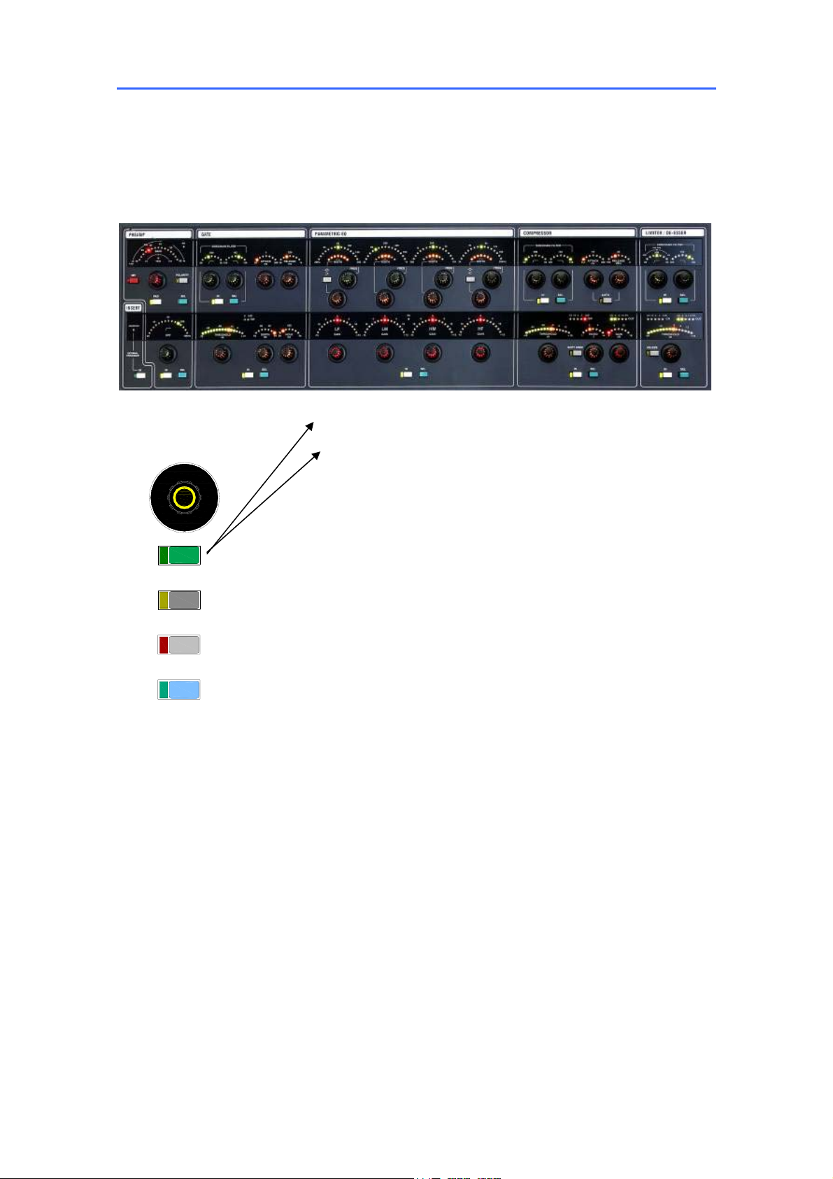
Rotary Controls These controls illuminate when they are
available. For example, the GATE controls turn off while a mix master
is selected. LED dials display the current setting for each control
when different channels are selected.
Peak and signal meters Peak indicators and signal meters are
presented throughout the signal path. The three dynamics processor
THRESHOLD controls feature signal meters that display beneath the
pointer on the LED dial so you can quickly see where to set the
control.
Note: iLive peak indication is multi-point sensing. If any part of
the signal chain peaks then the top PK! indicator of the control strip
meter illuminates. The red PK! indicator next to the associated
LAYER select key also lights.
Processing block IN keys Switch the processing in each
section in or out. The green indicator lights when the processing is
switched in. Metering including gain reduction remains present so
you can check the effect of a processor before switching it in.
Processing block SEL keys While the TouchScreen is in the
channel processing view pressing a processing section SEL key
opens its screen view. This is an alternative to touching the screen to
open a processing view such as PEQ or Compressor.
If you press and hold down a processing section SEL key you can
listen to the signal at that point in the signal chain using the
headphones and local monitor. The PAFL meters display the signal
level while pressed.
These SEL keys are also used for to copy/paste and reset sections of
the channel signal processing.
ALLEN&HEATH iLive Reference Guide AP6526 iss.3 25
Page 26
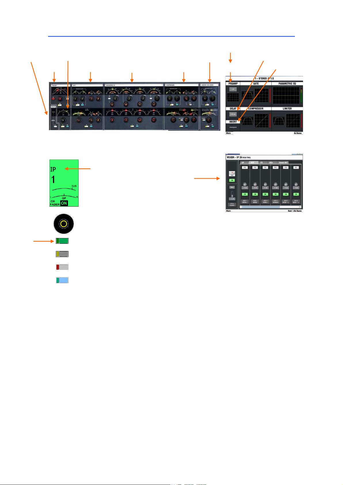
Using a SEL key to access Input Channel Parameters
Insert bypass
Preamp
Gate
PEQ
CHANNEL PARAMETER CONTROLS
Mono Input
Stereo Input
FX return via Input
Limiter / De-esser
Compressor
CH fader, pan, mute
Main mix assign
Group assign
Aux sends
FX sends
DCA assign
Direct Out level
Input socket patch
Delay HPF
Name and Colour Insert
PROCESSING VIEW
ROUTING VIEW
SEL
PAFL
MUTE
MIXMIX
PARAMETER CONTROLS - Press an IP (Input) channel SEL
key to access the parameters for that channel using the analogue
style controls in the processing block to the left of the screen. Every
input channel has preamp control, a HPF, gate, PEQ, compressor,
limiter/de-esser, delay and insert capability.
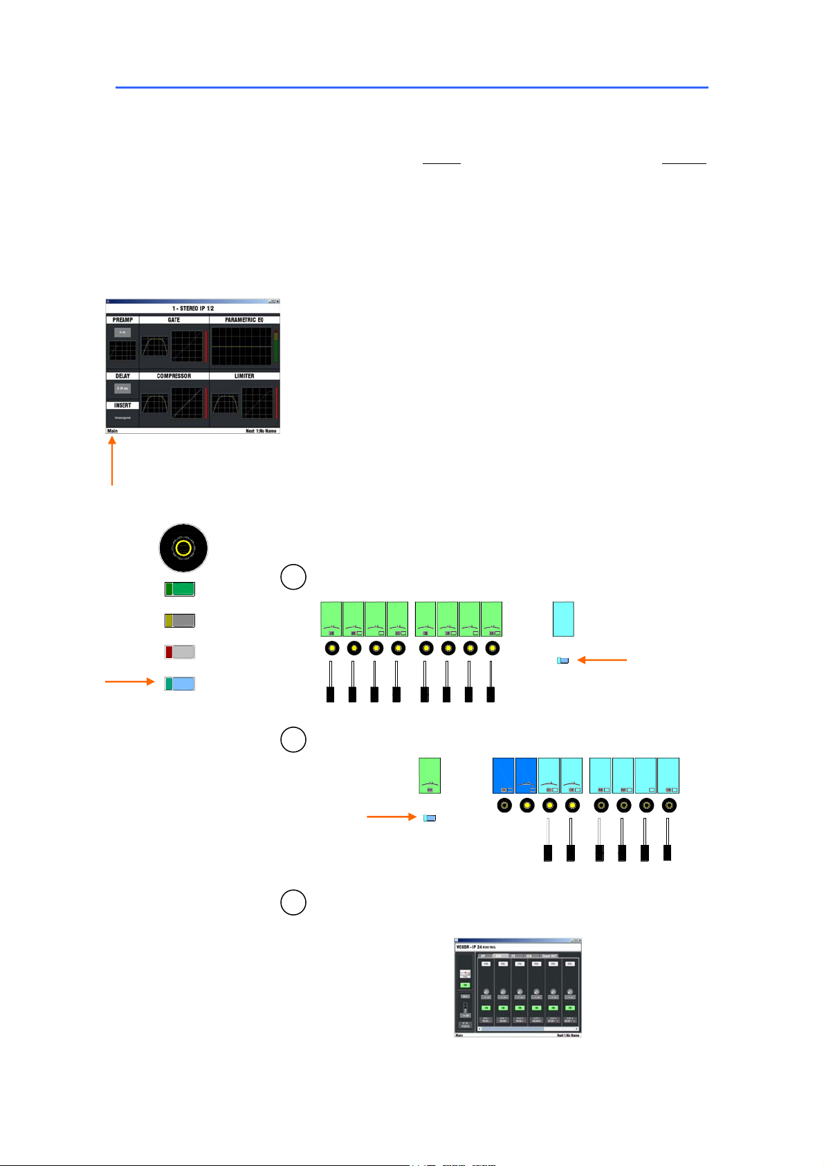
PROCESING VIEW - With all TouchScreen keys off, the
screen top view shows ‘thumbnails’ for each signal processor within
the channel. Touch the screen or press a processing block SEL key
to open the associated screen view. This gives you an alternative
graphical display and control of the signal processing, for example an
EQ or dynamics curve. Setup functions such as Input socket patch,
Insert, Delay, Name and Colour are accessed using the screen only.
Touch the Return button at the top right of the screen to return to the
top view. Each processing section includes a library for storing and
naming your favourite settings. These can be recalled into other
channels and transferred to another iLive or PC via USB key from
within the UTILITY/Configuration page.
ROUTING VIEW - With TouchScreen ROUTING page on, the
assignments and send levels for the selected channel are shown.
This gives you an alternative for controlling the mix using the screen
instead of the Surface MIX keys.
Note: Unlike several other digital mixing systems, the screen is
not an essential part of live mixing with iLive. Channel parameters
are adjusted using the analogue style rotary controls, switches and
displays within the processing block. Mix assignments, pre/post
settings, fader and send levels are adjusted using the Surface fader
control strips.
26 ALLEN&HEATH iLive Reference Guide AP6526 iss.3
Page 27
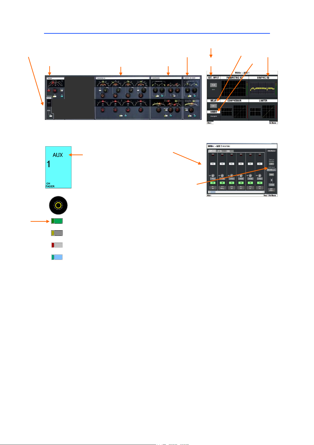
Using a SEL key to access Mix Master Parameters
Insert bypass
Ext Input Preamp
PEQ
CHANNEL PARAMETER CONTROLS
Mono,
stereo
Group
Aux
Main mix
Matrix
Limiter
Compressor
Master fader, pan, mute
Main mix assign
CH Aux sends
CH pre/post
FX sends
DCA assign
Sends on faders or rotaries
CH send source
Ext Input preamp
Name and Colour
PROCESSING VIEW
ROUTING VIEW
Delay
Insert
GEQ
SEL
PAFL
MUTE
MIXMIX
PARAMETER CONTROLS - Press a GP, AUX, FX, MAIN or
MTX (Mix) master SEL key to access the parameters for that master
using the analogue style controls in the processing block to the left of
the screen. Every mix master has both a PEQ and a third octave GEQ
as well as compressor, limiter, delay, external input and insert
capability.
PROCESING VIEW - With all TouchScreen keys off, the
screen top view shows ‘thumbnails’ for each signal processor within
the master. Touch the screen or press a processing block SEL key to
open the associated screen view. This gives you an alternative
graphical display and control of the signal processing, for example an
EQ or dynamics curve. Setup functions such as External input
source, Insert, Delay, Name and Colour are accessed using the
screen only. Touch the Return button at the top right of the screen to
return to the top view. Each processing section includes a library for
storing and naming your favourite settings. These can be recalled
into other channels and transferred to another iLive or PC via USB key
from within the UTILITY / Configuration page.
ROUTING VIEW - With TouchScreen ROUTING page on, the
assignments and send levels feeding the selected master are shown.
This gives you an alternative for controlling the mix using the screen
instead of the Surface MIX keys.
Note: Unlike several other digital mixing systems, the screen is
not an essential part of live mixing with iLive. Processing
parameters are adjusted using the analogue style rotary controls,
switches and displays within the processing block. Mix assignments,
pre/post settings, fader and send levels are adjusted using the
Surface fader control strips.
ALLEN&HEATH iLive Reference Guide AP6526 iss.3 27
Page 28
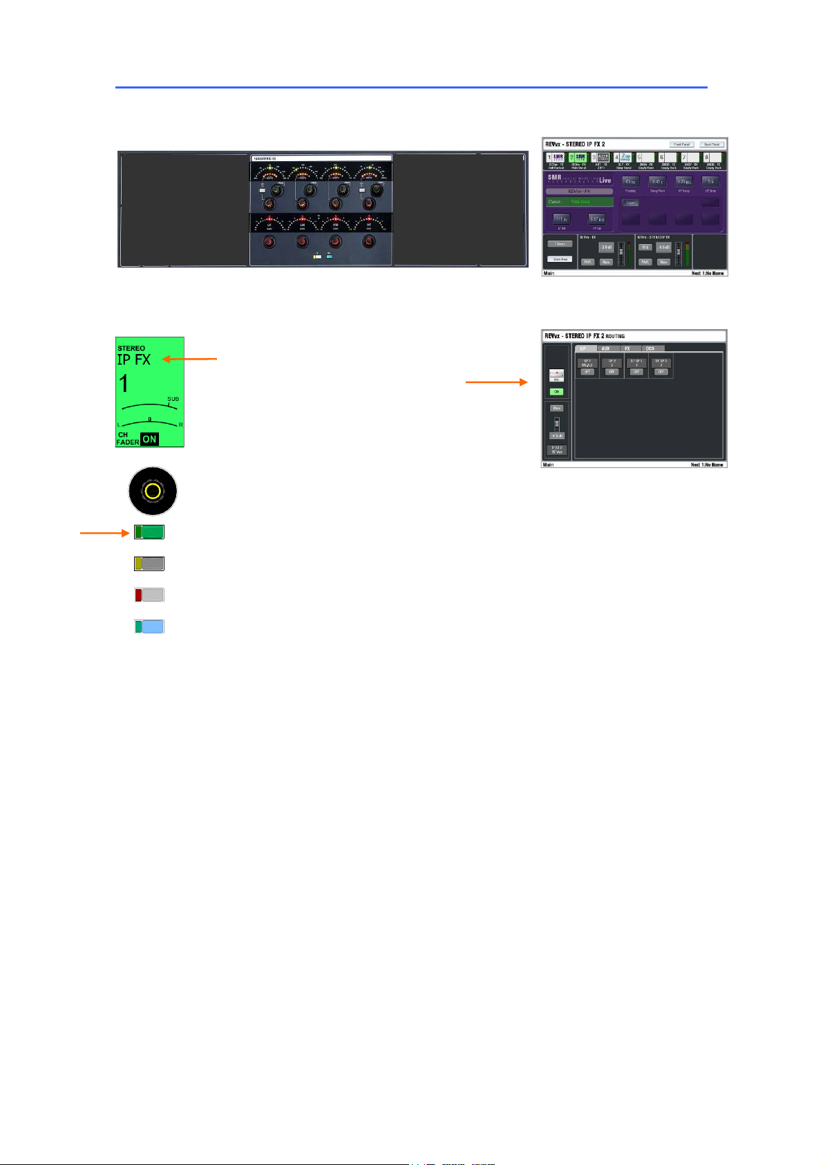
Using a SEL key to access Short FX Return Parameters
CHANNEL PARAMETER CONTROLS
FX short return
SEL
PAFL
MUTE
MIXMIX
PEQ
PROCESSING VIEW
ROUTING VIEW
CH fader, pan, mute
Main mix assign
Group assign
Aux sends
FX sends
DCA assign
The iLive ‘RackExtra’ DSP module provides a virtual rack to load up to
8 effects devices such as reverbs, delays and modulators. An FX
‘short return’ is a stereo input channel that returns the output of the
device to the mix. In addition to the parameters available within the
FX screen, a 4-band PEQ is provided on each. These returns add to
the channel count. You get 64 full channels plus 8 short stereo
returns, the equivalent of using an 80 channel analogue console.
PARAMETER CONTROLS - Press an IP FX channel SEL key
to access its PEQ settings using the analogue style controls in the
processing block to the left of the screen, and its processing
parameters and routing using the screen view.
PROCESING VIEW - With all TouchScreen keys off. Touch
the Front Panel button to display the parameter settings view, as if
you are working with a traditional rack mounted effects unit. Touch
the value boxes or controls to highlight them and use the screen
encoder to adjust the settings. Touch the Back Panel button to
display a ‘virtual’ view of the rear connectors. Use the drop down
menus to use the device in a Mix/Return loop (system effect such as
reverb) or inserted into a channel. You can feed a system effect from
a mono or stereo mix bus or direct output, and return it via a short
return or full channel. The screen also displays the send/return levels,
mutes and PAFL, and provides access to a library to recall factory
presets or store your own settings.
ROUTING VIEW - With TouchScreen ROUTING page on, the
assignments and send levels for the selected device are shown. This
gives you an alternative for controlling the FX mix using the screen
instead of the Surface MIX keys.
28 ALLEN&HEATH iLive Reference Guide AP6526 iss.3
Page 29
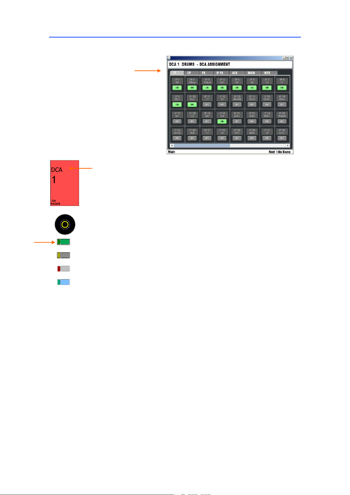
Using a SEL key to access DCA Settings
Assign from:
Input channels
FX return channels
Group masters
Aux masters
Main mix masters
Matrix masters
DCA master
With all TouchScreen keys off press a DCA master strip SEL key to
open its assignment view. Touch the screen buttons to toggle the
assignments on or off. The screen provides an alternative to using
the MIX keys to view and change DCA assignments.
SEL
PAFL
MUTE
MIXMIX
ALLEN&HEATH iLive Reference Guide AP6526 iss.3 29
Page 30
Surface basics – The MIX key
The primary function of the fader control strip MIX keys is to access the routing and levels for the different
mixes, and to assign the DCAs. This is fundamental to mixing with iLive giving you quick access with full
fader or rotary encoder control of every mix. The active MIX determines the function of the fader/encoder
area of the Surface. You can view the mix from the master (all sources to a mix) or from the channel
(sends to all the mixes). When you turn off a MIX key the default main mix (if configured) is automatically
selected. The blue LED indicators and strip LCDs display the current mix status. These keys are also
used to copy or reset mix levels and assignments, and for other functions including the assignment of
channel safes and talkback destinations. Assignment functions require a press and hold operation which
avoids mistakes through leaving the console in a setup mode.
Note: It is important that the operator becomes familiar with the
function of the SEL and MIX keys. These make mixing with iLive
very quick and intuitive once learned.
Note: To avoid mistakes while mixing we recommend that you
return to your main mix after making changes to your Groups,
Auxes, FX sends, Matrix or DCAs. Do this by pressing the currently
active MIX key to turn it off, or selecting the main mix again, or
pressing any MIX key on then off.
The TouchScreen lower status toolbar displays which mix is currently
active.
SEL
PAFL
MUTE
MIXMIX
Three ways to work with the mix:
All sends feeding one mix - Press a master MIX key.
1
IP
1
PAN
LR
AUX
IP
IP
3
2
PAN
PAN
LR
LR
AUX
PRE
IP
4
LR
AUX
PRE
PAN
AUX
PRE
IP
IP
6
5
PAN
PAN
LR
LR
AUX
IP
LR
AUX
PRE
7
PAN
IP
LR
AUX
PRE
8
PAN
AUX
PRE
All sends from one channel - Press a channel MIX key.
2
Input
IP
1
PAN
LR
CH
FADER
MIXMIX
GP
1
PRE
FADERCHFADER
TouchScreen ROUTING view - Press a channel or master SEL key
3
while the TouchScreen ROUTING page is active.
STEREO
STEREO
GP
AUX
2
IEM1
PAN
PAN
LR
LR
CH
PRE
STEREO
AUX
IEM2
CH
FADER
MIXMIX
STEREO
AUX
IEM2
PAN
LR
PRE
Master
AUX
WDG1
PRE
AUX
AUX
WDG2
WDG3
PRE
PRE
AUX
WDG4
PRE
PRE
TouchScreen
30 ALLEN&HEATH iLive Reference Guide AP6526 iss.3
Page 31

Using the Master MIX key - View all sends feeding one mix.
Select mix
Assign channels
Set Pre/Post fade
Adjust send levels
Adjust stereo pan
1. Press MIX on the mix master strip. View the current settings on the
channel strip LCDs and faders/rotaries.
2. To assign individual channels to the mix, hold down the ASSIGN key
and then press channel MIX keys to toggle them on or off. The strip
LCDs display an ‘ON’ icon when assigned. To assign all channels on
or off, hold down ASSIGN and then press the master MIX key to
toggle all on or off.
3. To set individual sends
pre or post-fade, hold down the PRE/POST
key and then press channel SEL keys to toggle them pre or post.
The strip LCDs display a ‘PRE’ icon when set to pre-fade. To set all
sends pre or post, hold down PRE/POST and then press the master
SEL key to toggle all.
4. For aux, FX and matrix mixes, the faders or rotaries become the
sends depending on the setting of the ‘Send on Rotaries’ button in
the ROUTING screen with master strip SEL active. If a rotary send,
then the faders remain as channel faders. For groups and DCAs (no
send levels), the faders and encoders remain unaffected.
5. For stereo aux and matrix sends, the rotaries become the PAN
controls. If a stereo send is configured for rotary levels then the
second (PAN) function as accessed by holding down the ROTARY
SHIFT key while turning the encoder. In this case the strip LCD
displays two dials.
This channel is
set post-fade
Current mix
status
This channel is
set pre-fade
IP
1
PAN
LR
AUX
SEL
MIXMIX
This channel is
not assigned
IP
2
PAN
LR
SEL
MIXMIX
IP
3
PAN
LR
AUX
PRE
SEL
MIXMIX
This channel
is assigned
IP
4
PAN
LR
AUX
PRE
SEL
MIXMIX
IP
4
PAN
LR
LEV
AUX
CH
PRE
FADER
AUX
PRE
Master
STEREO
AUX
IEM2
CH
FADER
5
ROTARY SHIFT
PRE/POST FADE
PRE/POST FADE
SEL
3
ASSIGN
ASSIGN
2
4
Rotary mix
Send levels on rotaries. Pan on
shifted rotaries if stereo mix.
MIXMIX
1
Fader mix
Send levels on faders. Pan on
rotaries if stereo mix.
ALLEN&HEATH iLive Reference Guide AP6526 iss.3 31
Page 32

Using the Channel MIX key - View all sends from one channel.
Select mix
Assign to mixes
Set Pre/Post fade
Adjust send levels
Adjust stereo pan
IP
1
PAN
LR
CH
FADER
1. Press MIX on an input channel strip. View the current sends and
assignments from that channel on the master strip LCDs and
faders/rotaries.
2. To assign to individual groups or sends, hold down the ASSIGN key
and then press master MIX keys to toggle them on or off. The master
strip LCDs display an ‘ON’ icon when the channel is assigned to it.
There is no ‘assign to all’ function.
3. To set individual sends pre or post-fade, hold down the PRE/POST
key and then press the related master SEL keys to toggle them pre or
post. The strip LCDs display a ‘PRE’ icon when set to pre-fade.
4. For aux, FX and matrix mixes, the faders or rotaries become the
sends depending on the setting of the ‘Send on Rotaries’ button in
the ROUTING screen with master strip SEL active. If a rotary send,
then they remain as master faders. For groups and DCAs (no send
levels), the faders and encoders remain unaffected.
5. For stereo aux and matrix sends, the rotaries become the PAN
controls. If a stereo send is configured for rotary levels then the
second (PAN) function as accessed by holding down the ROTARY
SHIFT key while turning the encoder. In this case the strip LCD
displays two dials.
The channel is
assigned to this mix
STEREO
AUX
IEM1
PAN
LR
STEREO
AUX
IEM2
PAN
LR
PRE
PRE
STEREO
STEREO
AUX
AUX
IEM1
IEM1
PAN
PAN
LR
LR
LEV
LEV
AUX
AUX
CH
PRE
FADER
PRE
The channel send to
this mix is set pre-fade
AUX
WDG1
PRE
AUX
WDG2
PRE
5
ROTARY SHIFT
Current mix
status
PRE/POST FADE
SEL
PRE/POST FADE
SEL
SEL
SEL
SEL
3
ASSIGN
MIXMIX
1
Rotary mix
ASSIGN
2
4
MIXMIX
MIXMIX
MIXMIX
MIXMIX
Send levels on rotaries. Pan on
shifted rotaries if stereo mix.
Fader mix
Send levels on faders. Pan on
rotaries if stereo mix.
32 ALLEN&HEATH iLive Reference Guide AP6526 iss.3
Page 33

Channel and Mix processing
iLive provides plenty of signal processing for its input channels, effects returns, mix masters and up to 8
internal FX devices. This replaces the large racks of outboard equipment that typically accompany the
traditional analogue mixing system. iLive has a huge amount of DSP power to make its processing
available to all channels at all times. You do not need to allocate processing from a limited resource of
DSP. The processing is instantly accessible on selecting a channel or mix, with dedicated analogue style
controls and alternative TouchScreen control.
PREAMP (Channel only)
Input patch bay Select the input source for the
channel from the Device drop down menu and
press Apply to confirm. This lets you rearrange
your patch according to how things are plugged up
on stage, split signals into two or more channels,
select from remote sources such as an EtherSound
Note: To select phantom power using
the processing block 48V key hold it
down for 0.5 second. This is to protect
against accidental operation. Red PP
LEDs light on the iLive MIC/LINE input
modules when phantom power is
detected on their sockets, whether from
their own mic preamp or an external
sources. These are not available on the
T Series.
or ACE mic splitter and more. Channel sources
include:
Unassigned
Available MixRack input socket
Available Surface input socket
Port A channels 33 to 62
Port B channels 1 to 64
Controls for preamp Gain, Polarity reverse, Pad and
48V phantom power are presented if a MIC/LINE
input is selected. These remotely control the
analogue head amp in the MIC/LINE module.
Reduce the gain if any of the channel PK! indicators
light.
HPF The PREAMP includes a swept frequency
high pass filter with IN/OUT switch and sweep from
20Hz to 400Hz.
Name and Colour Touch the Name box to access
a touch keypad to enter a 5 character channel
name. Use the ‘Quick Menu’ view to store and
recall commonly used names. Touch the Colour
box to access a drop down menu to select the
channel (LCD backlight) colour (6 colours and off).
ALLEN&HEATH iLive Reference Guide AP6526 iss.3 33
Page 34

MixRack
Surface
Port A
Port B
Surface Talkback
Mix Master name and colour
PREAMP (DUAL MIC/LINE IN) If the dual input
module is detected then the screen includes a
touch button to select between the A an B input
connections.
PREAMP (DIGITAL IN) If a DIGITAL IN source is
selected then a +/-24dB level trim control, polarity
and source selection for one of AES, SPDIF, optical
inputs are provided. If Port A or Port B digital audio
network source is selected then a trim and polarity
switch are provided.
EXT. INPUT (Mix only)
You can patch a source as a mix master External
Input. To open up the view touch the EXT INPUT
section in the top level ‘thumbnails’ view for the
master.
Ext Input patch bay Select the input source from
the Device drop down menu and press Apply to
confirm.
Name and Colour The mix master name and
colour can also be set from within this view. Touch
the Name box to access a touch keypad to enter a
5 character name. Use the ‘Quick Menu’ view to
store and recall commonly used names. Touch the
Colour box to access a drop down menu to select
the (LCD backlight) colour (6 colours and off).
34 ALLEN&HEATH iLive Reference Guide AP6526 iss.3
Page 35

GATE (Channel only)
The noise gate provides a full set of controls and
signal metering as you would find on a top grade
outboard processor. A self keyed side chain filter
may be switched in or out. Use the controls or
screen to set the threshold (a signal meter displays
under the control to help you set this quickly),
depth (how much the gate attenuates), hold time
(how long the gate remains open after the signal
drops below the threshold), and dynamics. A
screen histogram displays the gate activity over
time.
INSERT (Channel and Mix)
A physical input and output socket may be
assigned as an insert send and return for a channel
if outboard processing is required. Configure this
by touching the top view INSERT box to open the
INSERT page. Select the sockets (devices) to use
for the send and return and the operating level
(+4dBu or -10dBV).
Note: In most cases it should not be necessary
to insert outboard processing. iLive features
plenty of high quality built-in processing on every
channel and mix output.
Note: Sockets assigned as inserts are not
available for use as channel or mix inputs or
outputs. To reuse the sockets first deassign the
associated inserts.
ALLEN&HEATH iLive Reference Guide AP6526 iss.3 35
Page 36

SEL
PEQ (Channel, FX return and Mix)
The equaliser is 4-band fully parametric with
cut/boost, swept frequency and width controls per
band. The HF and LF bands may be switched as
shelving, bell or pass type filters. The WIDTH
control turns off if the band is set as shelving. GAIN
turns off if the band is set as a pass type. The
TouchScreen gives you a graphical view of the EQ
curve and alternative data entry using touch boxes
and encoder.
As with most of the processing blocks, you can
store and name your settings as user libraries. You
can also copy the settings to other channels, or
reset them to give you a known starting point.
Frequency display RTA display
Reset GEQ band
PAFL
MUTE
MIXMIX
GEQ (Mix only)
A third octave graphic equaliser is provided for
every mix output. This gives you up to 32 GEQs
depending on how many mixes you have
configured. The GEQ has 25 bands from 63Hz to
16kHz. To access the GEQ touch the GEQ box in
the mix master top ‘thumbnail’ screen. Touch the
screen slider to highlight a frequency band. Use a
stylus, finger or the screen encoder to adjust the
setting.
Press the screen GEQ Fader Flip button or press
the GEQ FADER FLIP key next to the faders while
the SEL key for the master is active to present the
GEQ across the fader banks. Using the fader key
you can access the GEQ without having to open up
its TouchScreen page.
The faders become the cut/boost controls for the
frequency bands. The strip on the right becomes
the master for the mix so that you can adjust the
overall level while adjusting the frequencies. That
may present the master fader or a channel send
depending on which MIX was current when you
switched to GEQ fader mode.
The strip LCDs change colour to red and display
the frequency for each band. The strip SEL keys
reset individual bands to their centre ‘0’ position.
Their green LEDs turn on when the band is reset to
‘0’. The RTA is also displayed across the meters
while in GEQ faders mode. This follows the current
PAFL selection.
Press the screen or fader bay GEQ FADER FLIP key
again to toggle back to normal fader view (or to the
second GEQ layer on the smallest iLive-80 surface).
You can store your GEQ settings as user libraries,
and use the Surface edit keys to quickly copy and
reset settings.
36 ALLEN&HEATH iLive Reference Guide AP6526 iss.3
Page 37

COMPRESSOR (Channel and Mix)
The compressor provides a full set of traditional
controls and signal metering as you would find on a
top grade outboard processor. A self keyed side
chain filter may be switched in or out. Use the
controls or screen to set the threshold (a signal
meter displays under the control to help you set this
quickly), ratio (how much the signal is
compressed), and make-up gain (to compensate
for the lower output level after the signal is
compressed). Set the make-up gain so that the
average signal level is similar whether the
compressor is switched in or out. The Soft Knee
function changes (softens) the effect of the
compressor around the threshold point. The
dynamics may be manually adjusted using the
attack and release controls or set for Auto function
with a drop down menu to select the type of
compression required.
The screen provides a graphical view of how the
compressor has been set to respond. You can see
the point at which the compression starts and how
much the signal will be compressed by the
steepness of the slope. Below it is a histogram
which shows how the compressor has affected the
signal over a period of time.
You can store your compressor settings as user
libraries, and use the Surface edit keys with the
Processing Block or TouchScreen SEL keys to
quickly copy and reset settings.
ALLEN&HEATH iLive Reference Guide AP6526 iss.3 37
Page 38

LIMITER / DE-ESSER (Limiter on Channel
and Mix, De-Esser on Channel only)
This is the last of three dynamics processors
available on every input channel. It can be used
either as a ‘brick wall’ limiter to stop the threshold
level being exceeded or as a de-esser to filter out
the sibilance of a vocal source.
In limiter mode, the input signal is superimposed
on the threshold display dial for quick setting. The
limiter includes a side chain filter for frequency
selective limiting, gain reduction and output meters,
and a histogram to display how much limiting has
taken place over time.
In de-esser mode the threshold display becomes a
yellow bar rather than a dot and the Threshold
control adjusts the amount of de-ess depth
(attenuation) at the frequency set. Use the Ess
control to adjust the frequency to find and tune out
the sibilance. This will vary from voice to voice.
The histogram shows the amount of de-essing that
has taken place over time.
DELAY (Channel and Mix)
Access the Delay page by touching the DELAY box
in the top view channel processing screen. This
shows the delay settings for all inputs so you can
check and adjust the values relative to other
channels. Touch a box to highlight it, then use the
screen encoder to adjust its value. The encoder
has acceleration so you can make big changes by
spinning it fast, and fine adjustments by turning it
slowly. The Setup tab lets you view the settings as
feet, metres or milliseconds. Maximum input
channel delay is 170mS, Mix master delay is
340mS.
38 ALLEN&HEATH iLive Reference Guide AP6526 iss.3
Page 39

Introducing the FX
The iDR-64 ‘RackExtra’ DSP module provides a virtual ‘FX rack’ which can be configured with up to 8
processors including reverbs, delays, modulators and more. It also features a host of new routing
possibilities for patching FX inputs and outputs and configuring mix/return or inserted FX types.
FX Rack A virtual rack with 8 ‘slots’ for loading different types of effects
processor. This emulates loading up a typical 8U analogue system outboard
rack.
Inserted FX You can patch an FX processor into an Input channel, Group,
Aux, Main or Matrix signal patch. The effect is in line with the signal and
provides an on screen Dry/Wet control to balance between the original and
effect signal, and an IN switch to switch the effect in or bypass it. If the FX is
patched into a mono channel or mix its stereo output is combined into a mono
sum.
Mix>Return FX This patches the FX as a ‘system effect’ fed from a mix
bus or channel direct output, and returned via a dedicated FX ‘short’ return or
a full input channel. Traditional live sound effects such as reverb and delay
would be configured in this way. The FX parameters may be accessed by
pressing the strip SEL key if it is configured using dedicated FX mix buses or
FX short returns. The FX screen provides the associated master send and
return controls.
Note: The FX short returns are in addition to the 64 channels available in
a single rack iLive system. With 8 FX configured with their dedicated short
returns you therefore get a total of 80 channels equivalent to an analogue
system where the effects are returned using two mono channels each. Each
short return features a 4-band PEQ and can be routed to all the mixes.
CHANNEL
SENDS
CHANNEL
Patch from
Dedicated mono or stereo FXn bus
Mono or stereo AUX bus
Channel Direct Output
Inserted FX
Channel Signal Path
POL0HPF GATE PEQ
INSERT
Mix>Return FX
Internal FX
IN OUT
Internal FX
IN OUT
COMP LIM
DELAY
DE-ES
ON
DRY WET
FADER
MUTE
Patch to
Dedicated stereo FX IP (short return)
Mono or stereo IP channel (full return)
MIX
ALLEN&HEATH iLive Reference Guide AP6526 iss.3 39
Page 40

FX configuration
Send to the FX
(FX input)
Return from the FX
(FX output)
Send/Return
masters or Wet/Dry
controls depending
on configuration
Back Panel view - Configure the FX routing
Apply the
change
Touch the top right Back Panel button to open up the connections view. This
emulates patching up a typical outboard effects rack. Configure the FX device
as a send/return loop or inserted into a channel or mix signal path.
FX configuration Choose an option from the drop down menu:
Not Assigned The FX is not patched.
Insert The FX is inserted into a channel or mix signal path.
Choose from the list in the drop down menu. Touch Apply to
confirm. The lower part of the screen provides the IN
(bypass) button, Dry / Wet balance control, and input /
output meters for the FX.
Mix>Return This configures the FX as a ‘system effect
typical of the aux send, channel return loop used in live
mixing for reverb and delay effects. Touch Apply to confirm.
The lower part of the screen provides the send and return
master controls together with input and output metering.
Note that these controls are also available on the fader
control strips if assigned to them.
Patch from If configured as a Mix>Return FX then use this drop down
menu to choose which signal sends to the FX input:
Dedicated FX mix bus
Mono or Stereo Aux mix
Channel Direct Output
Note: The Direct Output selection follows its global
setting configured in the MIXRACK SETUP / Mixer Pref /
Direct Output page. As an FX source this would typically be
set to Follow Fader and Follow Mute.
Patch to If configured as a Mix>Return FX then use this drop down menu
to choose where the return from the FX routes to:
Dedicated stereo FX short return
Mono or stereo full IP channel
40 ALLEN&HEATH iLive Reference Guide AP6526 iss.3
Page 41

Select FX
rack slot
Highlight and
scroll through
effects presets
using encoder
Library of
FX presets
Front Panel view – Work with the FX parameters
Adjust
parameters
FX send and
return master
settings
Access FX
parameters
Access FX
sends
SEL
PAFL
MUTE
MIXMIX
Access FX parameters from the strips Press an FX send master
strip SEL key, or press an FX short return (IP FX) strip SEL key to open up the
FX screen. You can adjust the parameters (Front Panel view), configure the
routing (Back Panel view) and work with libraries.
Access FX parameters from the TouchScreen Press the FX key
below the TouchScreen to open up the FX page. Touch one of the 8
numbered boxes across the top to present the FX processor you want to work
with. These display FX number, type and user defined name. If the box is
blank and labelled as “Empty Rack” then this means an FX processor has not
been assigned to this slot. Open up the Library and recall a preset to load the
required processor.
Access the FX send mix from the strips Press an FX send master
strip MIX key to work with the fader (or encoder) view of all the channel sends
feeding that effect, or press an input channel strip MIX key to work with the
sends from that channel to all the mixes.
Access the FX send mix from the TouchScreen With the screen
in the ROUTING page, press any IP channel, FX return or FX master SEL key
and select the FX tab to view the related send settings. Touch the screen
controls and use the screen encoder to adjust the levels.
FX send and return master screen The lower part of the screen
displays the current settings of the FX send and return masters, or Wet/Dry
and Bypass controls if the FX is Inserted. You can also access the PEQ as a
popup here. This lets you adjust the master settings from the screen whilst
working with the FX parameters.
FX return PEQ and processing
The FX ‘short’ return channel (addition to the 64 input channels) adds a 4-band
PEQ which is accessible on the rotary controls in the channel processing block
or a popup in the screen. If you have configured the effect to return through a
full channel (part of the 64 channels) then you get all the processing normally
associated with an input channel.
ALLEN&HEATH iLive Reference Guide AP6526 iss.3 41
Page 42

Choose the FX – The FX preset library
Touch the Library button to open up the library list. The presets are grouped
into Factory, User and USB.
Factory Default presets that cannot be overwritten, and can be used
as the starting point for creating your own presets.
User Edited settings may be named and stored here for future
recall. You can transfer these to or from a USB key using the UTILITY
/ Configuration / Library Manager screen.
USB Presets read off a USB memory key so that you can use your
favourite settings on other iLive systems without the need to load
them as User presets.
Touch the button to open the list you want to choose from. Highlight the
preset you want, or use the screen encoder to scroll through the list. These
are grouped into FX types:
Reverbs
Delays
Modulators
Sub Harmonics
Gated Verbs
Recall Touch Recall to load the highlighted preset. The effect is loaded
instantly together with its associated panel layout as if you had loaded your
preferred effects device into your outboard rack.
Overwrite This button becomes available when you highlight an existing
user or USB preset. Touch it to overwrite that preset with the current
parameter settings. A confirm box pops up to prevent accidental overwriting of
your settings.
Store New Touch Store New to name and save a new preset. The touch
keypad opens. Type in the name. The settings are stored as a new user
preset when you enter the name.
Exit Library Touch this button to close the library list and return to the FX
Front or Rear panel view.
42 ALLEN&HEATH iLive Reference Guide AP6526 iss.3
Page 43

Arena 1
Arena 2
Chamber Large
Chamber Mid
Chamber Small
EMT + Echo
EMT 250
EMT HF Vocal
EMT Large
EMT Live
Hall 480
Hall 481 Live
Hall 482 Live
Hall Barfoot
Hall Brass
Hall Bright
Hall Choral HF
Hall Drums
Hall Echo
Hall Large
Hall Massive
Hall Natural Small
Hall Small Vocal
Hall Small Stage
Hall Strings
Hall Wide Large
Hall Wide Small
Overheads
Plate Big Echo
Plate Bright
Plate Gold Dly’d
Plate Gold US
Plate Keys Barfoot
Plate Perc
Plate Small Space
Plate Snare
Plate Vocal
Plate Vocal F
Room KickBox
Room Large
Room Live Drums
Room PianoBar
Room Small
Room Speech
Slap Reverse
Slap Verb
Delay 2tap
Delay Brass
Delay Kraftwerk
Delay Perc
Delay Sax
Delay Shimmer
Delay Slap
Delay Stereo
Delay Vocal
Delay Vocal2
Reverbs - SMR
Spatial Modelling Reverberator. These provide high quality stereo reverb
effects based around 4 complex spatial models - Classic, Hall, Room and EMT.
Each of these models employs different reflection and decay algorithms to
provide natural sound spaces.
The SMR provides top layer controls essential in a live mixing situation
including 24dB/octave LF and HF filters, pre-delay, decay time, HF decay and
HF slope. These are always present on the FX Front Panel view. In addition
you can open ‘Expert’ pages which give you control of many additional
parameters for fine tuning the effect.
Delays
These generate separate left and right delay outputs from a mono’d input feed.
Individual tap indicators flash at the current tap rates set. Touch a tap button
to highlight it and use the screen encoder to adjust its value, or tap the button
at the rate you want to set the value.
Delay time can be adjusted from 5ms to 1.36 seconds. You can enter a
separate rate for the left and right delays, or you can link left and right to work
in mono with a single delay time by touching the Link button. The Fine
controls let you fine tune the times and set up echoes that are difficult to tap.
Other controls include 24dB/octave variable frequency Filters, Feedback
(regeneration) with low pass damping filter, and a stereo width control. Scatter
changes the delay pattern between left and right.
ALLEN&HEATH iLive Reference Guide AP6526 iss.3 43
Page 44

ADT 2Trk Vox
ADT Choral Dly
ADT Classic
ADT EkoChorus
Chorus Bright
Chorus Classic
Chorus Deep
Modulation FX - ADT
The ADT DOUBLER is an automatic double tracking module for creating short
echo/chorusing effects, classic double tracking and ‘slapback’ tape delay
loops. It emulates the classic ADT effects that are popular in enhancing
sources such as vocals and guitars in live sound mixing. It can also create a
subtle stereo sound field that can help produce ambience in a stereo in-ear
monitor or recording mix. The algorithm can create stereo double and quad
tracked voices from a mono input. Thickness creates flutter modulation in the
delay voices. There is also a stereo width enhancer and the tracked voices
can be auto panned in the stereo field to further enhance the effect.
Modulation FX - Chorus
This module emulates the classic chorus generators of the late 1980’s, through
3 stereo-field emulations. These can be switched in different combinations
creating many different stereo fields. All switches up gives no stereo
enhancement. The key traditional Rate and Depth controls cover the centre
panel. The LFO driving the modulator can be switched sine or rectified to
change the sound of the effect. The auto-panning section pans the chorus
voices giving stereo level shimmer, another classic modulator effect.
Modulation FX - Flange
Flange Classic
Flange Hard
Flange Jangle
Flange Space
Electric Flange provides 3 classic emulations - ‘ambient’ a light subtle ambient
sound, ‘vintage’ a classic silky sound from the birth of tape machine flanging
and untameable a ‘wild’ flange. The numerous LFO modulators and stereo
splitting techniques found in popular pedal flange effects have been emulated
here. For classic deep flange set stereo split and stereo spread off, pick
triangular modulation, vintage and adjust the DEPTH and REGENERATE
controls. The manual switch overrides the LFO for manual flange sweeps, a
feature found only on a few historic flangers.
44 ALLEN&HEATH iLive Reference Guide AP6526 iss.3
Page 45

Gate Echo
Gate RevPan
Gate Short
Gated Big Pan
Gated Drum Big
Gated Drums Sml
Gated Kick
Gated Rev
Gated Snare
Gated Vocal
Gated Verb
‘Gated Verb’ hosts the classic 80’s emulation plus ‘panned’ and ‘powerbox’
gated reverb presets. The user interface gives instant access to lo-cut hi-cut
decay spectrum filters and the gate envelope controls. We depart from the
80’s and provide a visual representation of the gate time domain envelope
helping the engineer ‘see’ the sound effect. Also included are mono, stereo
and wide imaging options and decay diffusion.
Classic Nonlinear - emulates the faithful 80’s classic gated reverb. Even left
and right distribution with de-correlated and diffuse reverb.
Panner - rapid panning between Left/Right in the reverb, creates short time
movement effects.
Powerbox - maximum power in gated energy, not as de-correlated as classic
non-linear.
Lo Cut 20Hz - 6 KHz, 24dB/octave filter to control decay spectrum
Hi Cut 400Hz – 20KHz, 12dB/octave filter to control decay spectrum
0 - 170ms adjustable pre-delay prior to attack starting
Attack, Hold, Release Time period for gate to open, remain open, and close
Maximum open gate length (attack + hold + release) = 500ms.
Mono/Stereo/Wide - option to set field output image.
Diffusion - from ‘clear’ (low diffusion) to ‘rich’ (highly diffused)
Empty rack
Recalling the ‘Empty Rack’ from the Library removes the current FX type
loaded. The screen displays a space as if a unit had been removed from a
traditional outboard rack. Recall a library preset to load in another FX device.
ALLEN&HEATH iLive Reference Guide AP6526 iss.3 45
Page 46

Patching the Outputs
Press the OUTPUTS key below the TouchScreen to access the output routing patch bays. These virtual
patch panels display the physical and digital audio network output sockets recognised by the system and
let you route any signal to any output.
Tabs to select patch
bay
Touch the socket or
scroll through the
available network
channels
OUTPUTS
MixRack The tab displays the user name
assigned to the MixRack. The system identifies the
output modules currently loaded (iLive) or fixed
sockets available (T Series) and displays a physical
socket view. Touch a socket to view its current
assignment. Choose a source from the drop down
menu, highlight the Channel Number box and use
the encoder to scroll through the channel numbers.
Touch Apply to confirm.
Work with a Single or a Range of sockets. For a
range, touch the first then the last. Enter the
Source type, Start and End channel numbers.
Touch Apply to confirm.
Choose the signal to
send to the socket.:
Not Patched
Mono or stereo Mix
Mix Bus Out
Input Direct Out
MixRack Input
Port A/B source
PAFL monitor
Wedge monitor
IEM monitor
Use the screen
encoder to scroll
through the channels.
Surface The tab displays the user name
assigned to the Surface. The system identifies the
output modules currently loaded (iLive) or fixed
sockets available (T Series) to the Surface. Assign
as described above.
Port A This tab is available if the iLive EtherSound
ESA network option is fitted. You can assign
outputs to ESA channels 33 to 62. Channels 1 to
32 are reserved to transport audio from the MixRack
to the Surface audio module slots A to D. Channels
63, 64 transport the PAFL monitor signal from the
MixRack to the Surface.
Port B This tab is available if a network option
card is fitted to Port B. EtherSound or ACE may be
fitted. You can assign outputs to Port B channels 1
to 64.
46 ALLEN&HEATH iLive Reference Guide AP6526 iss.3
Page 47

Output Sources The user assigned name is displayed below the channel
number. If a channel is not available a red cross appears.
Note: If sockets have been assigned as INSERT Sends then they are not
available to be assigned using the OUTPUTS page. To re-use the socket,
first unassign it using the INSERT screen associated with that input or mix.
Choose the Source from:
Not Patched The socket is unassigned. No signal present.
Mono or Stereo Group Post processing, post fader Group mix
output.
Mono or Stereo Aux Post processing, post fader Aux mix
output.
Main Post processing, post fader Main mix output. The channel
number ranges from 1 to 4 and depends on the main mix currently
configured, for example LCRSub type 1=L, 2=R, 3=C, 4=Sub.
Mono or Stereo Matrix Post processing, post fader Matrix mix
output.
Input Direct Output From the assigned channel number. The
direct output source is globally set in the MIXRACK / Mixer Pref /
Direct Output page. You can choose the point in the signal path and
whether it follows the channel MUTE and FADER functions. It is
common to assign channel direct outputs to multitrack inputs when
recording a live show typically set Post Preamp.
MixRack inputs This routes the output of the MixRack input
preamps directly to the output sockets. The signal is sourced just
after the ADC converter and before the channel processing. For
example, use these sources to provide a digital mic splitter via Port B
for FOH/Monitor mixing, or to record directly off the mic preamps.
Note: For firmware current at the time of printing this guide, the
Surface inputs are not available as sources. Use the Input Direct
Outputs to access these signals.
Bus Outs Assign the pre fader, pre processing mix signals to the
sockets. For example, use these sources when linking two systems
together to expand the number of inputs feeding the mix.
Note: For firmware current at the time of printing this guide,
channel expansion by connecting 2 racks to 1 surface is not yet
supported. This is planned for a future firmware release.
Port A / B sources Assign signals directly from the Port A or B
digital audio network options to the sockets. For example, route the
Main mix from the FOH system to sockets on the Monitor System
Rack over the Port B split.
PAFL L/R Output from the system stereo PAFL monitor. Assign to
a pair of MixRack sockets to connect to the Surface headphones/local
monitor system using analogue cables when an iLive system does
not have the Port A option fitted. The rear of the iLive Surface
provides analogue monitor input sockets for this purpose. These are
not available on the T Series.
Mono or Stereo Wedge / IEM Routes PAFL monitor signals
controlled by Wedge or IEM master strips to the sockets. Used for
the monitor application.
ALLEN&HEATH iLive Reference Guide AP6526 iss.3 47
Page 48

Using DCA groups
iLive provides 16 DCA groups. These behave in a similar way to conventional analogue console VCA
groups. You may assign as many of these as you choose to the Surface strips. The DCA master fader
does not physically move the assigned channel faders. Instead, it adjusts the levels at the channel fader
point in the same familiar way as traditional VCA mixing. iLive lets you assign any combination of input
channels and mix masters to one or more DCA groups. This lets you create multiple nested DCA
grouping for complex mixing applications if required.
ASSIGN channels or mix masters to the DCA group using
SEL
PAFL
MUTE
MIXMIX
10
5
0
5
10
20
30
40
Use DCA
master MUTE
key as the mute
group master
Set and leave
the DCA master
fader at ‘0’
position.
DCA master
the DCA master SEL screen, channel ROUTING screens, or the DCA
master MIX key ASSIGN function. If a channel is assigned to one or
more DCA groups then its ‘DCA’ icon turns on.
DCA master fader For normal operation set the DCA master
fader to its unity ‘0’ position. At this position the assigned channel
levels are not affected. Adjustments are made relative to this position.
PAFL key Sends a mix of all the signals assigned to the DCA
group to the headphones/local monitor system. The AFL function lets
you listen to the post fader stereo ‘in-place’ contribution of the group
of signals to the mix. PFL lets you quickly check a group of signals
for presence or problems before bringing up the faders.
MUTE key Muting the DCA master mutes all assigned channels.
This remotely actions the channel mutes. All sends from those
channels are muted.
Note: The channel LCD ‘DCA’ icons flash to indicate DCA muting.
The red MUTE indicators on channels muted by the DCA master do
not light. This separates indication of manual and DCA muting. The
T Series includes a dedicated DCA MUTE LED indicator below each
strip LCD window.
On = channel
assigned to one or
more DCA groups.
Flashing = channel
muted by one or
more DCA masters.
Note: If you remove DCA masters from the strips first check that
you have unassigned all channels from them or left their master
faders at the ‘0’ unity position. This prevents problems with ‘losing’
channel signals if the master faders of the removed DCA groups are
down.
Creating Mute Groups
You can use a DCA group as a Mute group by setting and leaving its
master fader at the unity ‘0’ position. Assign channels to the group in
the usual way. Use the master MUTE key to mute the assigned
channels.
The SoftKeys to the right of the TouchScreen can be assigned as
DCA group Mutes. This means that, once assigned, you can ‘bury’
these DCA master strips on a layer you do not use very often and
then use the SoftKeys as your Mute Group masters.
48 ALLEN&HEATH iLive Reference Guide AP6526 iss.3
Page 49

Channel Ganging
Ganging lets you link selected processing and mix parameters between input channels or masters, for
example the EQ, gate and compressor of a stereo keyboard, or the GEQ of the L and R main mix. iLive
lets you create up to 8 gangs with up to 8 channels in each. Ganging does not include the input Preamp
(gain).
Note: Although you can configure stereo
channels, Ganging is the preferred method for
linking channels when mixing live. Creating and
removing gangs can be carried out quickly ‘on the
fly’ while mixing. However, configuring stereo
channels using the MIXRACK SETUP / Mixer
Config screen resets the DSP architecture, takes a
while to complete, and should only be used for
setting up ‘permanent’ stereo channels, for example
walk-in music players and external effects returns.
Creating a channel gang
SEL
SEL
To enter Ganging Setup mode and view and assign
ganged input or mix master channel parameters,
PAFL
PAFL
select the TouchScreen MIXRACK / Ganging page.
Ganged channels must be compatible input or mix
MUTE
MUTE
types. Up to 8 gangs can be assigned with up to 8
channels each. The parameters available to be
MIXMIX
MIXMIX
ganged are known as the 'Attributes'. These include
processing such as EQ and dynamics, delay,
routing levels and assignments and mutes.
Touch a numbered Gang box in the left hand pane.
Press the SEL key on the first channel strip you
want to gang. Now touch the screen Attributes tab
and highlight the parameters you want to gang.
Touch Apply to accept the changes. Press the SEL
keys for the other channels you want to add to the
gang.
The channels currently ganged are shown in the
Members tab and on the related fader strip SEL
keys. To remove gangs use the strip SEL keys or
the Remove buttons in the Members tab.
Note: Do not leave the screen in the Ganging
page. To restore normal operation of the strip SEL
keys make sure you exit the Ganging setup screen.
ALLEN&HEATH iLive Reference Guide AP6526 iss.3 49
Page 50

Using the COPY / PASTE /RESET edit keys
iLive provides a quick and intuitive edit function to copy or reset settings between channels, processing
blocks and mixes. This uses dedicated edit keys on the Surface rather than complex screen menus.
Information
3
iLive-144 Surface
1
2
4
T-80 Surface
COPY / PASTE / RESET keys These functions are protected
from accidental operation. Pressing one of these keys by itself does
nothing. The edit function is actioned only if the key is first held down
and then a SEL or MIX key elsewhere on the surface is pressed while
it is held.
The lower toolbar of the TouchScreen displays information about the
edit operation, for example what is currently held on the clipboard, or
whether an action is valid or not.
You can copy or reset whole channels or selected blocks of
parameters, for example setting up all the processing for a vocal
channel as a starting point and then copying it to other vocal
channels. You can work with just one block of parameters, for
example to copy a Compressor across a range of instrument
channels.
You can copy or reset a whole mix or the mix parameters of just one
channel, for example as a starting point for several in-ear monitors.
Note: When using the edit keys make sure the TouchScreen is in
normal mixing mode, not in MIXRACK, SURFACE or
NAME&COLOUR mode. These modes take over the function of the
strip SEL keys.
50 ALLEN&HEATH iLive Reference Guide AP6526 iss.3
Page 51

COPY Hold down COPY then press the SEL or MIX key
associated with the parameters you want to copy. This puts the
parameters on to a ‘clipboard’ to be pasted later. Hold with:
1 Channel or mix SEL key – Copies all the processing associated
with the channel.
Note: The input PREAMP gain, pad and 48V settings are not
copied. The physical input is independent of the channel and may
be associated with other channels too.
2 Processing block SEL key – Copies just the parameters
associated with the selected block, for example a PEQ or Gate. To
copy the GEQ touch the screen SEL button while holding down
COPY.
3 Channel MIX key – Copies the mix settings of one channel to
another including the send levels, stereo send image, assignments
and pre/post settings. Does not copy the fader and mute settings.
4 Output master MIX key – Copies the whole mix from one mix to
another including all channel send levels, stereo send image,
assignments, pre/post settings and global send source.
PASTE Hold down PASTE. The lower toolbar of the TouchScreen
displays information about the parameters currently held on the
clipboard. You can only paste like for like information. The screen
warns you when the operation is not valid. You can paste the
parameters to multiple channels or mixes. While holding down
PASTE, press:
Strip SEL key to paste the whole or partial parameters held on the
clipboard,
Strip MIX key to paste the whole or channel mix parameters held on
the clipboard.
RESET Hold down RESET and then press a strip or processing
block SEL or MIX key to reset its associated parameters to factory
default, for example PEQ or GEQ flat.
Note: Resetting a MIX affects its assignments and send levels
only. It does not change the Pre/Post settings, Source selection or
Mute status.
Reset parameters
Group mix = All assignments off
Aux mix = All ON, Send levels down
Main mix = All ON, Pan centre, Faders down
Matrix = All ON, Send levels down
ALLEN&HEATH iLive Reference Guide AP6526 iss.3 51
Page 52

The METERS screen
Press the METERS key below the TouchScreen to view pages of audio meters. You can configure and
view up to 4 ‘User’ meter pages. The RTA frequency analysis display is available within this view. The
User meters and RTA are also accessible on the Status page for convenience while mixing live. These
meters views are in addition to the extensive physical metering provided on the iLive Surface.
Meter display
Up to 16 meters
Meters pages User pages
METERS
RTA
Standard meter views Touch a button in the
lower part of the screen to view a channel, mix
master, FX or matrix meter page. The page can
display up to 16 meters including associated Gate,
Compressor and Limiter gain reduction status
indication.
Pressing the METERS key always returns to the
meters page last viewed.
User meter views Touch one of the 4 User
buttons to open up a user definable meters view.
These can be named and customised to suit your
application and mix configuration.
Touch the Customise button at the top right of the
screen to design your meter page. Add meters
from the tabs displayed. You can insert spaces
between groups of meters and delete meters from
the view. Touch Apply to confirm the edit.
RTA display iLive features a built in RTA (Real
Time Analyser) which displays a frequency analysis
of signals monitored using the PAFL system. This
is displayed as a third octave meters view accessed
from the METERS or STATUS screens, or shown
across the Surface strip meters in GEQ on faders
mode.
52 ALLEN&HEATH iLive Reference Guide AP6526 iss.3
Page 53

PAFL monitor system
L
iLive features a comprehensive engineer’s monitoring system with headphones and local monitor outputs
available at the Surface, and headphones duplicated at the MixRack. The audio anywhere in the signal
path can be listened to using these monitor outputs, and checked on the dedicated PAFL meters.
Dedicated Surface and TouchScreen controls and user preferences let you configure the monitor system
the way you want to work. For a dedicated Monitor mixing application you can assign Surface strips as
the engineer’s Wedge and IEM monitor masters.
Press and hold
SEL keys
Strip controls
SEL
PAFL
MUTE
MIXMIX
MixRack PAF
indicators
Headphones
¼” and 3.5mm
LOCAL
PHONES
MONO
MONITOR
PAFL
SOLO-IN-PLACE
OUTPUT AFL
PAFL
INPUT AFL
ACTIVE
PK!
+9
+6
+3
0
-3
-6
-9
-12
-16
-20
-30
RL
CLEAR ALL
SIP SAFES
ENTER
100
100
Solo-in-Place
and
PAFL master
Surface controls and connections
PAFL keys
check the signal associated with the strip. Depending on the setting of the
PFL/AFL master keys, you can check the signal before the fader (PFL) or after
the fader (AFL).
The yellow indicator next to the key lights when PAFL is active. Yellow CHK
indicators next to the associated sockets on the iLive audio modules also light
(not available on T Series). This is very useful in helping you or the stage
technician checking the patching of the sockets or when troubleshooting
troublesome sources such as radio mics.
The strip SEL and/or MIX keys can be linked to the PAFL key operation. For
more information on this refer to the TouchScreen PAFL Functions page later
in this section.
Input channel PAFL overrides Mix master PAFL. This means you can listen
to a monitor mix using an Aux master PAFL, then check an input source by
pressing its channel PAFL. Releasing the channel PAFL restores the Aux
master PAFL.
Processing block SEL key Listen function Press and hold any
SEL key in the processing control section for more than ½ second to send the
audio at that point in the signal path to the monitor. For example, you can
press the PREAMP SEL key to check the signal before the EQ and dynamics,
and then the COMPRESSOR SEL key to listen to the effect after compression.
You can also listen to the side chain signal affecting a gate or compressor.
Each fader control strip includes a PAFL key. Press this to
ALLEN&HEATH iLive Reference Guide AP6526 iss.3 53
Page 54

PFL/AFL mode keys Master keys to the right of the strips select the
function of the PAFL keys to be PFL (pre-fade listen) or AFL (after-fade listen).
Signals are monitored in mono or stereo depending on their configuration.
AFL is pre-mute so you can check it before sending it, and ‘stereo in-place’ so
you can check it after the pan and image controls. The function can be set
independently for the input channels and mix master outputs. Normal setting
is PFL for the inputs (check the signals before you bring up the faders), and
AFL for the outputs (check the signals being sent from the console).
PAFL meters Displays the level of the selected PAFL source. Separate
meters for the left and right signals of a stereo source. Mono signals are
displayed equally on both meters.
PAFL active indicators These light when one or more PAFL keys is
selected. There are separate indicators for active input or output.
CLEAR ALL key Press to clear the current PAFL selections. If both a
channel PAFL and a mix master PAFL are active, then press once to clear the
channel PAFL and twice to also clear the master PAFL.
PHONES level control Adjusts the level of the monitored signal in the
engineer’s headphones.
LOCAL level control Adjusts the level of the monitored signal sent to the
Surface rear panel LOCAL MONITOR outputs.
SOLO-IN-PLACE
OUTPUT AFL
PAFL
INPUT AFL
ACTIVE
CLEAR ALL
SIP SAFES
PAFL
PK!
+9
+6
+3
0
-3
-6
-9
-12
-16
-20
-30
MONO switch Sums left and right signals in the headphones and local
monitor outputs.
PHONES sockets Two headphones sockets are provided at the front of
the iLive Surface under the armrest, or on the right hand side of the T Series
Surface. One is a standard ¼”, the other a 3.5mm mini-jack ideal for plugging
in a headset or ear piece equipped with the smaller jack. Both may be
plugged at the same time.
LOCAL MONITOR output A pair of balanced, line level XLR
connections on the rear of the iLive Surface, or TRS jacks on the rear of the T
Series lets you connect an amplifier or powered speakers as a local monitor.
RL
ENTER
Solo-in-Place (SIP)
The iLive SIP system lets you listen to the contribution of single channels in the
main mix by muting all other channels. It does this using the channel MUTE
keys.
SIP is protected from accidental operation while mixing live by requiring a two
key press to enter the SIP mode. Hold down the blue SIP SAFES key and
then press SIP. To exit SIP mode simply press SIP.
To make selected input channels and masters safe from SIP so that they are
not muted when a channel is soloed, hold down the SIP SAFES key and press
the associated strip MIX keys. The strip LCD SAFE icon displays for channels
made safe while in SIP mode. It is typical to make the main mix, monitor and
FX sends and FX returns safe in this way. Press CLEAR ALL to clear the SIP
selection while in this mode.
Note: SIP is known as ‘destructive’ as it affects the main FOH mix. It is
intended for use during rehearsal or sound check only. For standard signal
monitoring use the system PAFL function.
54 ALLEN&HEATH iLive Reference Guide AP6526 iss.3
Page 55

PAFL IN sockets This pair of balanced, line level XLR inputs on the rear
of the iLive Surface lets you add an external signal to the PAFL mix. Two
applications are:
iLive Surface No ESA
LOCAL MON OUT
XLR CABLES
iDR10
If you are not using Port A (EtherSound) to provide audio at the surface you
can use analogue connections to route the PAFL signal from the MixRack to
the Surface. Assign the PAFL mix to a pair of XLR sockets on the MixRack
using the OUTPUTS screen. Plug XLR cables from the MixRack to the Surface
PAFL in sockets. The PAFL signal now feeds the Surface headphones and
local monitor system.
Add an external signal to the PAFL mix to mix in with the system PAFL
transported via ESA. For example, you could add a monitor loop from an inear rack, or comms from an external location. Use line level signals. This
signal is always present in the Surface headphones and local monitor.
Note: The Surface PAFL meter reads the system PAFL mix only. External
non-PAFL signals will be heard in the Surface headphones and local monitor
but not read on the PAFL meters.
Note: You can also use the Ext In to PAFL feature to add an external
signal to the PAFL system. This is accessed using the PAFL screen.
PAFL IN
LOCAL MONITOR
ASSIGN AS PAFL OUTPUTS
MixRack controls and connections
The MixRack includes a headphones amp which duplicates the PAFL signal
checked at the Surface. This is useful in letting the stage technician hear the
same signal being checked by the FOH engineer at the Surface, or when you
are using a laptop instead of a Surface.
PHONES level control Adjusts the level of the monitored signal in the
MixRack headphones feed.
PHONES socket Standard ¼” socket for stereo headphones.
CHK indicators Each socket on the audio modules fitted to the iDR10
MixRack and iLive Surface have a CHK indicator which lights when its
associated channel PAFL is active. Two light if the channel is stereo. If an
insert has been assigned to the channel then its send and return socket CHK
indicators light too. This is helpful in identifying which sockets are associated
with a channel, for example when working with the stage technician checking
the patching. This feature is not available for the T Series.
ALLEN&HEATH iLive Reference Guide AP6526 iss.3 55
Page 56

TouchScreen PAFL functions
Press the TouchScreen PAFL key to open a page of option settings for the
PAFL monitoring system. Set these according to your preferred way of
working. These settings are retained on power down.
MixRack input
Surface input
Port A source
Port B source
Surface Talkback mic
Ext IP Talk to PAFL Turns on or off the source assigned for external
talkback into the PAFL monitor. Open the Ext Talk to PAFL page to assign
the source. Use the drop down menu to choose the source. This facility lets
you set up a reverse talkback path, for example to let the monitor engineer talk
to the FOH engineer through the PAFL headphones.
Additive Mode
one PAFL key cancels the previous selection. With the Additive Mode button
selected the operating mode changes so that PAFL selections sum together.
Default operation is auto-cancel mode where pressing
IEM Mix to Headphones If you have assigned a Surface strip as the
engineer’s IEM master for a monitor application, you can configure the system
headphones monitor to follow the IEM master.
MIX switch follow Mix PAFL In this mode, pressing a fader strip PAFL
key automatically selects the associated mix master
opens up the associated mix on the faders / encoders / LCDs. This can be a
quick way of working letting you adjust the mix sends, assignments and
settings as you listen to each master.
MIX key and therefore
MIX switch follow Input PAFL Provides a similar link function for the
Input channel
SEL follow PAFL In this mode, pressing a fader strip PAFL key
automatically selects the associated SEL key and therefore opens up the
associated channel processing. This is convenient when you are using PAFL
to check the channel signals and want to adjust their parameters at the same
time. In this mode pressing SEL does not action the associated PAFL.
MIX keys to follow PAFL presses.
AFL trim Lets you adjust the balance between PFL and AFL monitoring in
situations where the average AFL level is much quieter than PFL. Touch the
AFL Trim box and use the screen encoder to increase the level by up to 12dB.
Main to PAFL Levels Touch these boxes and turn the screen rotary
encoder to set the level of the main mix heard in the PAFL monitor when no
PAFL is active. If you want the monitor to be quiet when PAFL is inactive then
set them to –inf (off). You can save your Main to PAFL levels as user libraries
to recall your preferred settings later or transfer them via USB key.
56 ALLEN&HEATH iLive Reference Guide AP6526 iss.3
Page 57

Engineer’s Wedge / IEM monitoring
The iLive and T Series are capable of being configured for dedicated monitor mixing. It can provide an
engineer's dual Wedge/IEM facility for monitor mixing with combinations of stage wedge speakers and inear monitors. This lets you assign mono or stereo Wedge and/or IEM masters strips on the Surface.
Mixes sent to the stage wedges can be monitored in just the engineer's Wedge output, and mixes sent to
the in-ear systems can be checked using just the IEM output. Both these outputs use the same stereo
PAFL mix, but their mutes can be assigned to ensure the signal appears only at the wanted output. This
provides the equivalent of a top end monitor console dual listen function.
Assign Wedge and IEM master strips Use the
SURFACE / Strip Setup screen to assign one fader strip as
a mono or stereo Wedge master, and another as a mono or
stereo IEM master.
If you want full processing including GEQ and dynamics on
the engineer's outputs then make sure this is configured in
the MIXRACK / Mix Config screen. This will use up some of
the 32 DSP mix channels. Only configure this processing if
your application really needs it.
Patch the masters to sockets use the OUTPUTS
screen to patch the Wedge and IEM outputs to sockets on
either the MixRack or Surface. Plug these into your
monitoring system.
Assign mixes to the dual monitors Select the
MIX key on the Wedge master strip. Hold down the ASSIGN
key and press the Aux master MIX keys to assign the wedge
mixes. Do the same to assign the Auxes used for IEM mixes
to the IEM master strip. Make sure you turn off the
Wedge/IEM strip MIX keys when you have finished assigning
the mixes.
The dual monitor system uses just the one stereo PAFL bus.
It works by muting the monitor output not required.
Pressing PAFL on a mix master assigned to the Wedge
monitor will automatically MUTE the IEM monitor output.
Pressing PAFL on a mix master assigned to the IEM monitor
will automatically MUTE the Wedge monitor output.
Pressing PAFL on any input or mix master not assigned to
either the Wedge or IEM master will result in the signal not
affecting the mute status of the outputs. It is usual to leave
the input channels unassigned.
Note: You can unmute the Wedge or IEM master at any
time to listen to any PAFL signal in any output.
Other monitor application features:
Auto input PAFL override mix PAFL
Dual press PAFL CLEAR ALL
MIX and SEL key follow PAFL
SoftKey assign as PAFL/MIX/SEL combo
RTA follow PAFL
Aux mixing on faders
Configure any number of mono or stereo Auxes
Full processing and GEQ on every mix
ALLEN&HEATH iLive Reference Guide AP6526 iss.3 57
Page 58

Talkback system
iLive provides a fully featured engineer’s Talkback system. This uses dedicated Talk keys and is quick to
assign to the outputs without the need to access screen menus. The Surface has a built-in Talkback
microphone input which can link to the MixRack via the Port A digital audio network or an analogue
connection (iLive only). There are several options for setting up the system the way you want to work.
Analogue
Talkback output
TALKBACK
OUT
Assign talkback
destinations
using output
master MIX keys.
Talkback preferences and setup options
SOFT 1
SOFT 2
SOFT 3
SOFT 4
SOFT 5
SOFT 6
SOFT 7
SOFT 8
TB ASSIGN
TALK
LCD
DIM
LED
DIM
TB MIC
LOCAL
PHONES
48V
TALKBACK
MONITOR
MONO
maxmin
maxmin
maxmin
100
100
TB MIC input Balanced microphone level input. Plug in a wired handheld
or gooseneck microphone. If phantom power is required use a pointed object
to press in the recessed 48V switch. To avoid thumps make sure the
microphone is not live to its destinations when switching phantom power.
TALKBACK level Adjust the gain of the talkback mic. Start with the level
set to minimum.
TALKBACK OUT socket (Not available on T Series) Rear panel line
level balanced XLR to patch the talkback signal into the MixRack using an
analogue connection when the Port A option is not fitted.
TALK key Press this key to talk to the destinations currently assigned. Use
the SURFACE SETUP / Preferences screen to set either momentary (hold
down to talk) or latching (press to turn on, press again to turn off). Latching
operation may be preferred if you are using a handheld mic with built-in switch.
Note: The signal generator is disabled to that destination if Talkback is
active.
Assigning Talkback using the MIX keys
Hold down the TB ASSIGN key, then press the MIX keys on the fader strips of
the output masters you wish to talk to. This assigns the destinations. Press
these keys to toggle the assignments on or off. The MIX key blue indicators
light to display the current talkback destinations while the TB ASSIGN key is
held down.
Note: You can change the talkback assignments while the TALK key is
active. Hold down the TB ASSIGN key and tap the output master MIX keys
while talking to quickly change destinations.
Assigning Talkback using the TouchScreen
Go to the MIXRACK SETUP / Talkback / Assignment page. Use the touch
buttons to assign talkback to your chosen outputs.
58 ALLEN&HEATH iLive Reference Guide AP6526 iss.3
Page 59

Talkback setup and preferences
The lower part of the Source page provides
access to the preamp settings and meter if a
MIC/LINE input has been selected, or the
digital trim and meter if a digital input has been
selected. Use these to set the Talkback level.
TALK key action Select either momentary or
latching operation. Go to the SURFACE SETUP /
Preferences page. Set the Latching Talkback Talk
Switch option.
Talkback Source Choose the source for the
Talkback system from the drop down menu in the
MIXRACK SETUP / Talkback / Source page.
Unassigned No source. The Talkback system is
not used.
Surface Talkback Selects the Surface built-in TB
MIC input (default).
iDR MixRack Choose from any of the available
input sockets on the MixRack. Choose the slot
(position) and socket number (one of 8). You
would use one of these inputs if you wanted to plug
your talkback microphone directly into the MixRack,
or if you were transporting your iLive Surface
Talkback signal to the MixRack using the analogue
rather than Port A (EtherSound) connection.
iLive Surface Choose from any of the available
input sockets in the rear of the Surface.
Port A Choose a remote source via Port A option.
Port B Choose a remote source via Port B option.
Communication between FOH and Monitor systems
iLive presents many possibilities for arranging communication between the
FOH and stage positions in a dual console application. Signals can be
transported between the systems using the Port B digital audio link, and
mapped to mixes and sockets at either end. For example:
FOH talk to musicians on stage Use the Surface Talkback system. Plug in
a switched handheld microphone and choose the latched TALK switch
preference. Assign TB to a spare FOH Aux mix. Route that Aux via Port B and
assign it to a channel on the Monitor system. This becomes the FOH to stage
talkback enabled at FOH using the TALK switch.
FOH talk to monitor engineer Assign the same Surface Talkback mic as the
Ext Input source to another spare mix (Do not use TB assign as above). Route
that mix via Port B to the Monitor system and select it as the Ext Talk to PAFL
source on that system. This becomes the FOH talk to monitor when the
handheld mic is switched on. It is not affected by the FOH TALK switch which
can be turned off when the engineers want to talk to each other and not the
musicians.
Monitor talk to FOH engineer Similarly, the Monitor Surface Talkback can
be assigned to Port B and selected as the Ext Talk to PAFL at the FOH
console. These signals can also be mapped to available output sockets if you
want to use independent local loudspeakers for engineer communication.
ALLEN&HEATH iLive Reference Guide AP6526 iss.3 59
Page 60

SoftKeys
8 SoftKeys to the right of the TouchScreen can be assigned to
different functions to suit your application. For example, you could
use them as MUTE GROUP masters, to recall Scene memories,
quickly access processing or mix parameters of a certain channel or
master, send a MIDI message and more.
Working with Mute Groups Although iLive does not have
dedicated Mute Groups it does feature no less than 16 DCA groups.
Some of these could be configured as Mute groups simply by setting
and leaving their master faders at the normal ‘0’ unity gain position.
Assign channels to the group in the usual way and use the group
master MUTE switch to control the Mute Group. For example, DCA 1
to 8 could be used as true DCA groups for level control, while DCA 9
to 16 could be used as Mute groups with just switch control. These
DCA master strips could be assigned to a seldom used layer on the
Surface for Mute group assignment only. The master Mutes can be
operated using the Soft Keys giving you instant access to control your
eight Mute groups.
To find out more about assigning the SoftKey refer to the section on
Surface Setup later in this guide.
PL-Anet remote control
MIDI
PL-Anet is the proprietary Allen & Heath RS485 based serial control
network for connecting combinations of PL Series remote controllers
to iLive. Use standard CAT5 cables to connect PL Series controllers
to the iLive PL-Anet port either at the Surface or the MixRack. Make
sure the last PL controller has the end of line terminator plugged into
its output socket. For more information on using PL-Anet refer to the
user guide that comes with the controller.
Refer to the Allen & Heath web site for information on the range of PL
remote control devices available.
PL-6 The 8 faders can be assigned to control levels. The faders are
not motorised. You can set an option to allow the fader to ‘pick up’
the current level, or for the level to jump to the fader setting as soon
as it is moved.
PL-10 This has 8 rotary controls instead of faders. As they are
endless turn encoders with LED bars they always indicate and follow
the current levels and therefore make the PL-10 better suited than the
PL-6 in providing simultaneous control alongside the Surface.
Note: Only connect PL Series devices to the PL-Anet port. DC
voltage is present that may damage network and other devices if
connected.
MIDI IN, OUT and THRU connections are available at both the
MixRack and Surface. MIDI is tunnelled via the Ethernet control
connection between the MixRack and Surface which means devices
may be connected at either end.
Go to the UTILITY / Configuration / MIDI page to set the MIDI
channel number and access the MMC transport controls. You can
also assign SoftKeys and PL device controls to transmit custom MIDI
message strings. For the full MIDI implementation refer to the MIDI
chart later in this guide.
60 ALLEN&HEATH iLive Reference Guide AP6526 iss.3
Page 61

MIXRACK setup
The MixRack is the heart of the system and features a 64 channel x 32 mix bus audio architecture that is
fully configurable by the user. Once configured you can map the channels and masters to the Surface
strips and layers in any combination. You can also name and colour these so that the Surface strip LCDs
provide a visual coding that makes it very quick and easy to work with your mix. This means that you can
‘design’ your own mixer to suit your application and preferred way of working. Once configured you can
archive your settings as Scene and Show memories for future use or transfer to other iLive and T Series
systems.
This section explains the configuration of the MixRack, the DSP ‘mix engine’. The 64 input channels may
be configured as mono or stereo. This emulates the design of a traditional analogue console where a
certain number of stereo channels are provided for sources such as CD and sound effects players, effects
returns and audio for video. You can choose how many stereo channels you want. The 32 mix buses
may be configured into a traditional and very familiar architecture of mono or stereo Groups, Auxes, Main
mix and Matrix. The advantage offered by iLive is that you can choose how many of each type of mix you
configure as long as the total number does not exceed 32. You can even configure the Main mix from a
list of different types such as M, LR, LCR, LRSub and more. For example you may want to set the system
up for FOH operation one day, and dedicated Monitor the next. The FOH configuration can include a
combination of Groups, Auxes, up to 4way Main mix and a large number of Matrix feeds. On the other
hand, the Monitor configuration may comprise mostly mono and stereo Auxes and no Main mix or Matrix.
Both of these applications can be easily configured and stored.
To access the MixRack audio configuration press the MIXRACK SETUP key below the TouchScreen.
Overview of
current input and
mix audio
configuration
Menu buttons
Note: It is not intended that the MixRack configuration is
changed ‘on the fly’ during a sound check or performance. Plan
and configure this before you start your application. Changing the
configuration makes big changes to the DSP architecture of the
system and resets the mix parameters. iLive has plenty of buses so
you should be able to configure enough in your standard setup to
satisfy your most demanding application without the need to
reconfigure part way through.
Note: Changing the configuration resets channel and mix
parameters. If you want to keep your current settings you should
save all parameters to a Scene memory first before changing the
configuration. Recall this Scene to restore the parameters after the
configuration change.
MIXRACK
ALLEN&HEATH iLive Reference Guide AP6526 iss.3 61
Page 62

Top screen We refer to this as the ‘radar view’ as it provides an overview of the current
system configuration. Use the menu buttons to access and change the configuration and other
MixRack setup functions.
Input Channels view Tabs let you access all 64
input channels and the FX short returns.
Input source ‘R-B3’ means MixRack slot B socket
3. ‘EB 6’ means EtherSound ESB channel 6.
48V displays phantom power status.
Insert displays if an insert has been assigned.
Name User defined 5 character channel name.
Channel number DSP channel 1 to 64.
Mute displays the channel mute status.
Faders show the current channel level settings.
Direct Output routing shows the output sockets
associated with the direct outputs. If the output is
routed to more than one socket a ‘…’ is displayed.
Touch that part of the screen to toggle to the other
sockets assigned.
Mix Channels view Tabs let you view the current
status of the 32 mix buses and 8 internal FX buses.
External Input source ‘NotAs’ means a socket has
not been assigned as the external input. ‘S-C5’
means Surface slot C socket 5. ‘EA 36’ means
EtherSound ESA channel 36.
Type displays the type of mix configured.
Insert Displays if an insert has been assigned.
Name User defined 5 character mix name. The
background colour indicates mono or stereo mixes
configured.
Mix number sequence for each mix type.
Mute displays the mix mute status.
Faders show the current channel level settings.
Mix Output routing shows the output sockets
associated with the mix outputs. If the output is
routed to more than one socket a ‘…’ is displayed.
Touch that part of the screen to toggle to the other
sockets assigned.
Configure the global Direct
Output source and the digital
audio network settings.
Configure the audio bus
architecture and stereo input
channels
62 ALLEN&HEATH iLive Reference Guide AP6526 iss.3
Configure the Talkback
assignments and source.
Access the onboard signal
generator to route test signals
to the mixes.
Configure connected PL
device control functions.
Assign input channel and mix
master gangs to link processing
and mix parameters.
Page 63

Mixer Config page This screen lets you change the mono/stereo
configuration of the input channels, and the architecture of the mix buses.
Note: Changing these settings reconfigures the DSP architecture and
resets parameters. This can take up to 2 minutes to complete and is not
intended for ‘on the fly’ changes while live mixing. Set this up before you start
preparing for your show. Access to the Mix Configuration can be locked out
by setting Permissions for a guest user. To do this go to the UTILITY /
Configuration / Edit User Profiles page. Store your parameter settings as a
Scene before changing to recall after you have changed your configuration.
IP Stereo Displays the current mono/stereo
configuration of the 64 input channels. Stereo
channels are highlighted in green. Touch the
buttons to change the configuration. Related
odd/even pairs can be set as stereo.
This is intended for permanently configuring some
channels as stereo inputs for an application, for
example CD and SFX players. Stereo channels use
a single fader control strip each.
Touch Apply to accept the changes. A popup box
lets you confirm the reconfiguration.
Note: Use the Ganging function for on the fly
linking of channels for stereo sources while
mixing live. Gangs are set up using the MIXRACK
SETUP / Ganging page.
This part of the screen displays the
number of buses, FX and mix
outputs remaining. If you exceed
the maximum then a red cross is
displayed. Reduce the number if
this occurs.
Mixer Config Displays the current DSP mix bus
architecture. Touch boxes display and let you
change the number of each type of mono and
stereo mix, the type of Main mix, and whether to
provide processing for the engineer’s Wedge or
IEM monitor outputs.
To change the configuration touch a box to
highlight it, then use the screen rotary encoder to
increase or decrease the number.
FX Up to 8 internal FX
Buses Excluding the Matrix, up to 30 buses
be configured as mono or stereo Groups, Auxes,
FX and Main mix. The remaining 2 buses are
allocated to the system PAFL monitor. Note that
the FX buses and short returns are dedicated to
their related FX number.
Mix Outputs Up to 32 mix outputs may be
configured. These are the masters that provide full
processing including GEQ and can be patched to
the physical output sockets. They include the
Groups, Auxes, Main mix and Matrix but do not
include the internal FX as these are not routed to
the sockets. Stereo mixes use a single fader
control strip each.
Main mix Use the drop down menu to select the
main mix type you want. You can have no main
mix, for example if you are configuring a Monitor
console. The main mix may be up to 4way.
Processing on Wedge/IEM For monitor mixing
applications you can allocate output processing
(EQ, dynamics) to the engineers monitor outputs.
rack devices.
may
ALLEN&HEATH iLive Reference Guide AP6526 iss.3 63
Page 64

The Main Mix
iLive features a choice of many different configurations of main mix from mono
to 4way and with different types of image control. Note that due to the DSP
architecture the buses are always allocated in pairs. Therefore a main mono
‘M’ mix uses two buses, a 3way LCR mix uses four buses. The main mix
masters always use one strip per output. Therefore an LR mix uses two fader
strips, a 4way LCRSub mix uses four fader strips.
Main mix types
None Preferred if the system is configured as a dedicated Monitor console
typically with plenty of Auxes but no Main mix. In this case turning off an Aux
master strip MIX key reverts the faders to being channel and mix masters with
no assignments or pan function in view.
M Single bus mono main mix.
LR Traditional stereo mix with left/right PAN function per channel.
LRSub A unique 3way main mix that provides 3 master faders and a dual
control channel imaging system which lets you dial in the amount of sub level
using a dedicated control per channel. Innovated by Allen & Heath, it is a new
and more convenient way of mixing with separate sub bass feed than the
popular ‘Aux Fed Sub’ method. The rotary encoder becomes the PAN control.
Its shifted function is the SUB level control. Note that the SUB output is full
frequency range. Crossover processing is done typically using manufacturer
specific speaker system controllers.
LRM Similar to the above 3way mix but substituting ‘M’ for ‘SUB’. This
provides a convenient third output for driving a mono fill speaker.
LCR Traditional 3way LCR panning where the channel PAN control moves
the signal from left, through centre to right speakers.
LCRSub A 4way main mix with traditional 3way LCR panning and dedicated
SUB feed. The shifted function of the strip encoder provides the sub level
control.
LCRM Similar to the above but substituting ‘M’ for ‘SUB’.
LCRPlus A 3way LCR main mix pioneered by Allen & Heath. This provides
two image controls, PAN to position the signal between the L and R speakers,
and BLEND to position the signal between the LR speakers and C (centre).
Accepting the changes First ensure that you have stored the parameter
settings you want to keep as a Scene memory to recall after the configuration
change. Touch Apply to accept the changes you have made. A popup box
appears to let you confirm or escape from the changes.
Surface strip assignments Having made changes to your input and mix bus
configuration you may need to map your new inputs and masters to the fader
control strips across the four layers. Use the SURFACE SETUP screen to do
this.
Storing your configuration You can save your configuration and system
setup as a Show memory to use again in the future. This can be transferred
between iLive systems or archived to your PC via USB memory key. To
access the Show memories go to the UTILITY / Configuration / Show
Manager page.
64 ALLEN&HEATH iLive Reference Guide AP6526 iss.3
Page 65

Mixer Pref / Direct Output page This page lets you set the source to
the input channel direct outputs. The setting is global and affects all direct
outputs. You can choose the point within the channel signal path and whether
or not it follows the main channel mute and/or fader.
Global Direct Output Source Open the drop
down menu and select the point in the channel
signal path to feed the direct outputs. The list is in
signal processing order. The setting affects all 64
input channel direct outputs.
Follow Fader Touch button. When on, the signal
follows the fader level. It may be considered ‘postfade’ but note that the signal source is determined
by the drop down menu setting and may not be the
same as that at the main channel fader position.
Follow Mute Touch button. When on, the signal
set using the drop down menu follows the MUTE
key function.
Note: For recording individual channels to a
multitrack it is typical to source the signal
directly after the Preamp or HPF. It would
normally be set with Follow Fader off and Follow
Mute on.
Audio Sync/Networks page Presents the options for the audio
networking and clock source set up.
Restore ESA defaults (if EtherSound
option is fitted)
Audio Clock Source Choose the source of
the system digital clock sync – Internal, MixRack
Port B or DARS. If the MixRack is a slave getting its
channel audio via Port B from a master iLive, for
example in a split FOH/Monitor application then set
the source to MixRack Port B.
Remote Port status windows these display
information about any audio network options fitted
to Port A or B. A red cross indicates an error
detected.
Note: If the source is incorrectly set you may
get spurious meter readings and noises with no
signal present.
Restore ESA Defaults This resets the iLive
EtherSound ESA (Port A) network mapping to
factory default which maps CH1-32 to the Surface
audio slots. It is useful if the mapping has been
changed previously using an external EtherSound
monitor application and you want to restore a
known starting point.
Note: This does not affect the console ESA
patching, for example the ESA OUTPUTS. It
affects the mapping within the EtherSound network
which is configured using a laptop running the
Auvitran ES Monitor application.
Note: Restoring the ESA defaults requires a
complete system reboot.
ALLEN&HEATH iLive Reference Guide AP6526 iss.3 65
Page 66

Remote B configuration
Remote B Config Here you configure the way
the MixRack Port B EtherSound ESB network (if
fitted) is set up to work. This configures the
MixRack EtherSound interface cards so that the
slave audio is downstream of the master. In a
linked iLive system where one MixRack has the mic
preamps loaded and another gets its channel
sources from the first via ESB, set the first as the
MASTER and the second as the MASTER/SLAVE.
Note: The ESB config setting remains with the
system. It is remembered on power up. It is not
part of the Scene or Show memories. There is no
indicator to display the current setting. If you are
not sure how it is set simply set it again.
Refer to the Application Diagrams later in this
guide for examples on how to configure the system.
Quick Input Setup Two buttons provide a
convenient way to quickly configure all channel
inputs to get their source from either the local inputs
(normal stand alone system) or the Port B audio
network (linked system slave). This gives you a
starting point for setting your input sources.
Global Remote B Input sets CH 1-64 inputs to get
their sources from Port B channels 1-64. For
example, use this if the MixRack is a slave in a
linked FOH/Monitor or Recording system with
digital mic splitter using EtherSound or ACE.
Global Local Input sets the CH1-64 inputs to get
their sources from the local audio inputs in the
MixRack. It identifies the currently loaded modules
and applies them in the socket order it finds.
Note: Sockets currently assigned as insert
returns are ignored and the associated channel
sources are left unassigned.
66 ALLEN&HEATH iLive Reference Guide AP6526 iss.3
Page 67

Signal Generator page Provides a comprehensive tone / noise
generator which can be used for checking and setting up the system. The
generator settings are restored on power up and stored in the system Show
memories. They are not stored in Scene memories.
Signal type Choose the generator signal source
type:
Sine Pure sine wave tone. Touch the Frequency
box and use the screen encoder to adjust the
frequency of the tone. You an sweep from 20Hz to
20kHz.
White Noise Noise with linear response, equal
energy per Hz.
Pink Noise Noise with logarithmic response. This
is a very useful test source as it contains the full
bandwidth of audio frequencies with equal energy
per octave. Use this to quickly check the response
of a signal path or drivers in a loudspeaker system.
Band Pass Noise This is limited bandwidth noise
with its centre frequency sweepable from 20Hz to
20kHz.
Level Touch the Level box and use the screen
encoder to adjust the output level of the generator
from fully off to +18dB maximum.
Mute Turns off the signal generator.
Mixes There is one button per mix available. The
mix type and its name is identified next to the
button. These route the generator to the Group,
Aux and Matrix mixes. Touch a button to toggle it
on (green) or off (grey). This routes the signal
generator to any combination of the mix outputs.
The signal is routed to mix bus and is therefore
affected by the mix master processing and fader.
Mains The buttons in the lower part of the screen
route the generator to the configured main mix.
There may be 1 to 4 buttons depending on the type
of main mix configured. The buttons are positioned
here to keep them away from the other mix buttons
and avoid accidental routing to the main PA.
Note: To avoid unexpected loud signals start
with the generator Level turned down. We
recommend that you turn the level down and turn
off all the generator mix assignments after you have
finished using the generator.
ALLEN&HEATH iLive Reference Guide AP6526 iss.3 67
Page 68

SURFACE setup
Once the MixRack audio architecture has been configured using the MIXRACK SETUP screen, you can
assign the channels, mix masters, DCA group masters and Wedge/IEM masters to the Surface strips.
These are assigned to the strips within the fader banks and across the 4 layers, either one at a time or
across a range of strips. This is a quick process and changes to the strip assignments can be made on
the fly during the show. Assignments can be stored in the Scene memories for different ‘layouts’ for
different bands or scenes. Being able to assign the strips in any combination you choose lets you
‘design’ your own console layout. Together with the ability to name and colour the channels this gives
iLive its unique flexibility and makes the mixing experience very visual and intuitive.
To access the Surface setup press the SURFACE SETUP key below
the TouchScreen.
Assign single
strips or a
range within a
bank of faders
Channel type
Reset all
strips to
MixRack
config
SURFACE
Note: To give you a quick starting point you can choose from a selection
of factory ‘Template’ Show memories. These configure the whole system
including audio architecture and strip assignments as classic formats that
emulate the familiar layout of traditional analogue consoles. Start with a
Template show and recall the Scene associated with your Surface size if you
do not want to configure the strip layout from scratch. Once loaded you can
edit the format and archive it as a User Show for recall again later.
To work with the Show memories go to the UTILITY / Configuration / Show
Manager page.
Note: The SURFACE SETUP screen takes over the function of the control
strip SEL keys. Do not leave the TouchScreen in SURFACE SETUP mode.
Once you have made changes to the strip assignments exit SETUP mode by
turning off the key below the screen.
68 ALLEN&HEATH iLive Reference Guide AP6526 iss.3
Page 69

Assigning the Surface Strips
SEL
PAFL
MUTE
MIXMIX
SEL
PAFL
MUTE
MIXMIX
To assign a Single Strip Touch the Single Assignment button. Press
the SEL key on the strip you want to assign. Use the drop down menu to
select the Channel Type you wish to assign. Touch the Channel Number box
to highlight it and use the screen encoder to scroll to the number required.
Touch Apply to accept the change.
To assign a Block of Strips Touch the Block Assignment button.
Working from left to right in the same fader Bank, press the SEL key of the first
strip in the range you wish to assign. Now press the last in the range. All the
green SEL indicators in the selected range should light. Use the drop down
menu to select the Channel Type you wish to assign. Highlight the channel
number boxes to enter the start and end numbers required. Touch Apply to
accept the change
Note: Block assignment applies to strips in the same bank of faders. You
can assign a range across the layers in a bank of faders.
Strip types available
Unused - The strip is left blank
Input - Input channel. Stereo inputs use a single strip.
Input FX - Dedicated short FX return
Mono or stereo Group - Stereo masters use a single strip.
Mono or stereo Aux - Stereo masters use a single strip.
Mono or stereo FX - Dedicated FX send mix bus.
Main - One fader per main mix output, eg 3 for LCR.
Matrix - Stereo masters use a single strip.
DCA - Masters.
Mono or stereo Wedge or IEM - Engineer’s monitor masters
Reset All Strips This function is useful if you are connecting a Surface
with unrelated strip assignment to a MixRack. It automatically overwrites the
current assignments and configures all strips across all fader banks and layers
in a pre-determined order so that all channels, mix masters and DCA masters
can be viewed and accessed as a starting point.
Note: It is not usually necessary to use this function. If you are starting
with a new system or unrelated Surface and MixRack it is usually better to
recall a Template or User Show. This gives you a more workable starting point
as it presents a more conventional layout.
ALLEN&HEATH iLive Reference Guide AP6526 iss.3 69
Page 70

Unused
LED on/off
Mute
Fader up/down
Send level up/down
FX level up/down
PAFL
Scene recall
Custom MIDI string
Talkback assign
SEL key
MIX key
PAFL/SEL/MIX combo
Assigning the Soft Keys
8 SoftKeys to the right of the TouchScreen can be assigned to different
functions to suit your application. For example, you could use them as MUTE
GROUP masters, to recall Scene memories, quickly access processing or mix
parameters of a certain channel or master, send a MIDI message and more.
To assign the SoftKeys
Setup page to view and edit the assignments of the 8 user keys.
Touch a key button in the screen and use the drop down menu and number
box to change its switch assignment. You can also assign its associated LED
indicator. Select Auto-Link if you want the LED to automatically assign the
related function. Press Apply to accept the change.
The PAFL, SEL and MIX choice lets you simultaneously action a combination
of these functions for a selected channel or master. This is useful for monitor
mixing when you may wish to assign all the fader strips as input channels. The
processing, levels and PAFL for each of up to 8 mixes can be instantly
selected by simply pressing a Soft Key.
Select the TouchScreen SURFACE / SoftKey
70 ALLEN&HEATH iLive Reference Guide AP6526 iss.3
Page 71

Unused
LED on/off
Mute
Fader up/down
Send level up/down
FX level up/down
PAFL
Scene recall
Custom MIDI string
Talkback assign
Assigning PL Devices
Allen & Heath PL remote control device may be plugged into either the
MixRack or the Surface. These provide controls such as faders, rotary
encoders, switches, indicators and logic GPIO which may be assigned by the
user to suit the application. These controllers interface to the iLive using CAT5
cable via the RS485 based PL-Anet port. To find out more about the range of
PL devices available visit the Allen & Heath web site.
To assign PL controls For PL devices plugged into the Surface select
the TouchScreen SURFACE SETUP / PL-Anet Setup page to view and edit
the assignments of any PL Series remote control devices currently connected.
For PL devices at the MixRack select the MIXRACK SETUP / PL-Anet page.
Note: PL devices must be connected before assigning their controls. The
system identifies each device by type, their location (MixRack or Surface) and
order in which they are connected. Names may be applied to each PL location.
These are stored in the iLive not the PL devices.
Several remotes may be connected by daisy chaining PL-Anet CAT5 cables
between them. Make sure the the last device in the chain has its terminator
plugged in. If preferred, you can connect each with its own cable back to the
iLive by using the Allen & Heath PL-9 PL-Anet hub. This may be required for
on-stage personal monitor hookup. Check that all connected PL devices have
their green Power LEDs illuminated. If the LED is off or red then check the
cables and connections.
Note: The maximum number of PL devices connected depends on cable
length and device type. Refer to the PL Calculator spreadsheet on the Allen
& Heath iDR website to check your application.
Select the Unit and Device from the screen. Use the screen selection boxes to
scroll to the Control Type and Number you wish to assign. Use the drop down
Function and LED Setting menus to assign the required functions. Press Apply
to accept each change.
Each PL switch, LED, fader or encoder can be assigned in a similar way to the
Surface Soft Keys. Plan your application before starting, and save your settings
as a PL library item when you are finished. Libraries can be transferred
between systems via USB key.
Note: If you have assigned PL switches to recall Scenes then these
scenes should be transferred to or set up in the same way on the other
iLive you transfer PL libraries to.
ALLEN&HEATH iLive Reference Guide AP6526 iss.3 71
Page 72

The Surface ALT VIEW key
The Surface fader strip LCDs normally display the channel names. Hold down
the ALT VIEW key to display alternative information such as channel or socket
number, or dB value.
Choosing the function of the ALT VIEW key
Go to the SURFACE SETUP / Alt View Setup page and use the drop down
menu to select the ALT VIEW key function.
DSP Channel Displays the MixRack channel number 1 to 64.
dB Value Displays the value in dB associated with the current function of the
associated fader. This may be the main channel fader or a send level
depending on the status of the MIX keys.
Socket ID Displays the input or output physical socket associated with the
channel assigned to the strip.
R - = MixRack socket
S - = Surface socket
A - = Port A network channel
B - = Port B network channel
For example: R – B3 = MixRack slot B position 3
72 ALLEN&HEATH iLive Reference Guide AP6526 iss.3
Page 73

Setting the Surface Preferences
You can set user preferences for how the iLive Surface functions. Go to the
SURFACE SETUP / Preferences page.
Link Fader Banks Set the Surface fader banks for independent or linked
layer operation across all banks.
Display Parameter Values Display dB readings in the strip LCDs when
the faders or encoders are moved.
LCD Contrast Set the strip LCD contrast.
Note: The LCD contrast is reset to ‘10’ when the firmware is updated to a new
version. Adjust the contrast after carrying out the update if needed.
Latching Talk Switch Set the Surface TALK switch for momentary or
latching operation. Latched operation is convenient when you are using a
microphone with built-in switch. In this case leave the TALK switch turned on.
Enable Scene Up/Down/Go Keys Enable or disable the Surface
Scene up, down and GO keys. Unless you are using these for fast cue recall
during a theatre show we recommend you disable them to avoid accidental
operation.
Scene Editing Confirmation Enable Scene edit confirmation popup
screens to help prevent accidental overwriting of settings.
Temperature Choose degrees Celsius or Fahrenheit for temperature
display.
ALLEN&HEATH iLive Reference Guide AP6526 iss.3 73
Page 74

Name and Colour
Each Input channel, mix master and DCA master can have a 5 character name and one of 6 colours or no
backlight applied. The names appear on the strip LCDs and TouchScreen pages, and the colour affects
the strip LCD backlights. The LCDs form a virtual write-on strip that makes mixing with iLive a very visual
and intuitive experience. Note that all names and colours except the DCA masters can also be edited
from within the related channel processing SEL screens as an alternative to using the NAME & COLOUR
screen. However, the screen provides a quick way to change the colour of a range of strips or all
channels of a certain type
There are two ways to name and colour channels:
Channel Processing view
In normal mixing mode, press SEL to access the channel
processing. Make sure all screen keys are turned off so that
the channel parameters are displayed on the screen.
Navigate to the name and colour screen:
Input Channels - PREAMP screen
Mix Masters - EXT INPUT screen
DCA Masters – Use the NAME & COLOUR screen
Name & Colour screen
Press the TouchScreen NAME & COLOUR key.
Strip Select / Single Strip Select - Press a strip SEL key.
Touch Name to open the on-screen keypad. Touch Colour to
select a colour. Touch Apply.
Strip Select / Block Strip Select - Press the first SEL key
then the last in the range you want to colour. All green SEL
indicators in the range light. Touch Colour to select the
colour. Touch Apply.
Note - Naming is disabled in Block mode.
Channel Select - Select Channel Type and the range. Select
Colour and press Apply.
Note - To restore the SEL keys to normal mixing mode
turn off the NAME & COLOUR key.
Touch Reset to delete the name and restore the channel
number.
Quick Menu
A quick naming facility opens a second keypad to let you
create and store up to 48x of your most often used names.
To apply, press a strip SEL key and simply touch a name.
Touch Edit to edit or create new names.
Note – The user defined quick names are stored in the
Show memories. These get overwritten with the contents of
the Show when it is recalled.
74 ALLEN&HEATH iLive Reference Guide AP6526 iss.3
Page 75

User Profiles
iLive lets you set up and work with up to 8 'User Profiles'. You can set permissions and a password for
each to restrict operator access to certain functions.
The 'Admin' user (Administrator) has access to all functions and can set permissions and allocate
passwords if required for the other users. Up to 7 guest users may be configured and activated.
User Permissions:
Update Firmware
Input Stereo Assignment
Names and Colours
Network Setup
Network Connections
Bus Configuration
Scene Recall
Scene Manager (Store)
Show Manager
Outputs (socket patching)
Mixer Preferences
Signal generator
To set up User Profiles go to the TouchScreen
UTILITY / Configuration / Edit User Profiles page.
Touch a User button. Use the onscreen keypad to
enter a user Name and add a Comment. Set a
Password if required. Touch Set Permissions to
enable or disable access to certain functions. You
can also assign a Startup Scene which will recall
automatically when the user logs in. Select No
Startup Scene if none is required. Activate any user
profiles you want to appear in the Change User or
log in screen.
Note: Only set passwords if you really need to.
Make sure you keep a log of all passwords
allocated. Clearing passwords required resetting
internal jumpers and clearing the memories.
To log in as a different user go to the
TouchScreen UTILITY page and touch the Change
User button. If a password has been set then you
are prompted to enter it when you turn the system
on or lock or unlock the Surface.
ALLEN&HEATH iLive Reference Guide AP6526 iss.3 75
Page 76

Library memories
You can name, store and recall parameter settings as User libraries, or recall factory presets from the
Library pane in each processing screen.
Library types:
PEQ
GEQ
Noise Gate
Compressor
Limiter/De-esser
Full input channel processing
Full mix channel processing
FX emulations
PL-Anet setup
Touch the Library button to open up the library view. Select
a Factory, User or USB item and touch Recall to recall its
settings. Touch Store New to store the current settings as a
new User library item. This open the touch keypad to enter a
name.
Libraries can be archived to computer or transferred
between iLive systems using a USB key. Press the
TouchScreen UTILITY / Configuration / Library Manager
key to work with the USB library function. If you plug in a
USB key with libraries available these will be listed in the
related Library screens. You do not need to copy them to the
Surface to work with them. Copy libraries from the iLive to
the USB key to archive or transfer them.
Note: For iLive to see the Libraries on your USB key they
must be placed in an 'allenheath \ libraries’ folder in the
root directory of your key. If libraries have been previously
transferred from an iLive to the key then the folder should
exist already.
76 ALLEN&HEATH iLive Reference Guide AP6526 iss.3
Page 77

Scene memories
iLive has 250 Scene memories. These are 'snapshots' of all or a selection of the live mixing parameters.
They do not store the DSP bus configuration and user preferences.
Before starting go to the SURFACE / Preferences screen
and set the options to enable or disable the Scene
Up/Down/Go keys, and turn on or off the Scene Editing
Confirmation popup box. For the most secure operation we
recommend that you disable these keys and turn on the
confirmation popups.
Select the SCENE screen. Highlight a Scene in the left hand
list. Touch Name to open the onscreen keypad and enter a
name with up to 8 characters. Touch Description to add a
comment with up to 32 characters.
The quickest way to work with Scenes is to store everything.
Touch Store All to store all parameters to the Scene. Touch
Recall to overwrite the current iLive settings with the
contents of the memory. Once a Scene has contents stored
a green tick is displayed next to its name.
Note: To avoid losing important settings take care when
storing or recalling Scenes.
For more advanced applications you can choose what
parameters to put into a Scene so that only those are
overwritten. Touch Edit To open the list of available
parameters. Use the + and - buttons to expand or collapse
the list, and the View buttons to select parameters by type or
channel. You can make Single or Multiple selections.
Highlight your selection and touch Add to add them to the
Scene list on the right. You can add and remove items from
the Scene, and update items already in the Scene with the
current console settings. When you have finished editing the
contents Return to the Scene Manager page.
Touch Update to update just the existing contents of a
Scene with the current console settings. Unlike Store All this
does not add everything to the Scene.
You can copy, paste and delete Scenes. Highlight a Scene
in the list and touch Copy. Highlight another Scene and
touch Paste. The contents of the first Scene are pasted into
the second. The name is not copied. If that Scene was
empty a green tick will now appear. You can paste the
Scene into multiple locations. When you Delete a Scene its
contents are removed and the name reverts to 'No Name'.
Tip - You can use copy/paste to quickly set up several
Scenes with the same content list, and then use Update to
store different parameter settings for each as the sound
check or show progresses.
Scene Recall Safes lets you make selected input
channels and mix masters 'safe' so that their parameters are
not overwritten when a Scene is recalled. Hold down the
SCENE SAFES key and press the strip MIX keys on
channels you want to make safe. The SAFE icon in the strip
LCDs turns on for channels made safe.
Note: The mic preamp is not included in channels made
safe. This is because preamps can be patched to any input
channel, may be mapped to more than one channel, or used
as sources to other parts of the system which may not be
associated with the channel you want to make safe.
Update existing contents of Scene
Settings available to add
STEREO
IP
DCA
NAME
PAN
LR
LEV
AUX
CH
FADER
SEL
PAFL
PRE
MUTE
MIXMIX
Recall Scene
Store all settings
Settings in the Scene
ALLEN&HEATH iLive Reference Guide AP6526 iss.3 77
Page 78

Using the Edit SCENE CONTENTS page
Add selected items to a 'partial' scene
SCENE CONTENTS
Console
Settings
Tree view
+ - + -
Expand Collapse tree
To update all settings currently in a Scene 'Select All'
SCENE CONTENTS
Console
Settings
+ - + -
Update selected items in a 'partial' scene
SCENE CONTENTS
Console
Settings
+ - + -
SCENE CONTENTS
Console
Settings
+ - + -
Add
Remove
Update
Add
Remove
Update
Add
Remove
Update
Expand Collapse tree
Remove items from a scene
Add
Remove
Update
Settings
in scene
Select All
Settings
in scene
Settings
in scene
Settings
in scene
Add selected parameters to a Scene You can store
‘partial’ Scenes. Select items from the list in the left hand
window to add to the scene. Expand and collapse the tree
list using the + and – buttons. Touch the Multiple Select
button to select more than one item at a time. Now touch
the Add button to add the items to the Scene. If they already
exist in the Scene their values will be updated. Once added,
the item displays in the right hand window. Choose either
Processing View or Channel View. The diagram that follows
lists the available parameters in the left hand window and
illustrates where in the signal chain the parameters exist.
Update all parameters already in a Scene Highlight
Select All in the right hand Scene Contents window. Now
touch the Update button in the centre of the screen. The
existing parameters stored in the Scene are updated with the
current system settings. This does not add any parameters.
It updates the values of parameters previously added to the
Scene.
Note: A quicker method is to use the SCENE page
Update button.
Update selected parameters in a Scene You can update
the settings of one or a selection of items already in the
Scene. Select the items you want to update from the list in
the right hand window. Expand and collapse the tree list
using the + and – buttons. Touch the Multiple Select button
to select more than one item at a time. Now touch the
Update button in the centre of the screen. The Scene
parameters are overwritten with the current console settings.
Choose either Processing View or Channel View to find the
parameters you want to update.
Remove items from a Scene Highlight items in the right
hand window to remove from the Scene. To remove
everything highlight Select All. Then touch the Remove
button in the centre of the screen.
For example, adding All then removing items may be quicker
than starting by adding individual items.
Note: To remove all items you can also use the Delete
Scene function from the SCENES screen top page. This
also clears the Scene name.
Expand Collapse tree
78 ALLEN&HEATH iLive Reference Guide AP6526 iss.3
Page 79

Scene parameters The diagram below lists the items that may be selected and added to
the Scene memories. It also illustrates where the different parameters exist in the signal chain.
The items are arranged as a tree view. You can expand and collapse tree items, and view it by
Processing type or Channel number.
Note: Scenes do not include the Mix Configuration, EtherSound
Configuration, and some User Preferences.
Note: The Mic Preamps are not part of the Input Channel
Processing. This is because they are not permanently associated
with the channels. They can be patched to different combinations of
channels and used for other signals such as external inputs and insert
returns.
Note: The Mix levels, mutes and assignments are treated as one
item each for Input channels, Mix masters and DCA masters. Mix
parameters including the input faders, pan, mutes, all assignments,
pre/post settings, Aux and FX sends to the masters are part of the
Input Mixer item. At the time of release of this guide you cannot add,
for example, just the mutes or DCA assignments to the Scenes, or
work with the sends of one or a selection of channels (all 64 are
treated as one item). Note that you can use Scene SAFES to protect
selected channels.
Note: The Patch bay is treated as a single item. Recalling a Scene
with the patch bay included overwrites all input, insert and output
patching.
SCENES
x 250
Name (8char)
Comment (32 char)
Select All
Audio Clock Source
Channel Names and Colours
Delays
Digital Source Select
Input Channel Processing
Internal FX
Mic Preamps
Mix Channel Processing
Mixers
Multi Output Settings
Patchbays
Strip Assignments
SETTINGS STORED IN SCENE MEMORIES
Mic Pre
Selection of available
MIC/LINE
Socket 1-8
GAIN
Slot A-J
PAD
48V
+
-
Digital Source Select
Selection of available
AES
SPDIF
OPTO
SOURCE
ESA
ESB
Patchbay
ADC
INPUT P/BAY
CHANNEL
SOURCES
INSERT
RETURNS
MIX EXT IN
SOURCES
TALKBACK
SOURCE
ESA ESB
ROUTING
Clock Source
Select
DIGITAL SYNC
Internal, ESB, DARS
All
Processing or Channel view
Tree Structure
DCA Channel (all)
Input Channel (all)
Mix Channel (all)
Available Sockets (sel)
Input Channel (all)
Mix Channel (all)
Units 1-8 parameter settings (sel)
Available Sockets (sel)
DCA Lev & Mutes
Available Sockets (sel)
(all)
Input Channel Mixer
Mix Channel Mixer
Bank 1,2,3 (sel)
All levels, mutes, assignments
Strip Assignments
Select Bank 1, 2, 3
Patchbay
POL
0
TRIM
PEQ
INSERT
HPF GATE PEQ
IN/OUT
+4/-10
DIR OUT SOURCE
Input Channel Processing
Selection of 64
GEQ
AUX SEND SOURCE
Mix Channel Processing
Selection of 32
COMP LIM
DE-ES
DIR OUT
TRIM
Patchbay
COMP LIM
Compressor (sel)
Dir Out Global Source (all)
Direct Out Trim (sel)
Gate (sel)
HPF (sel)
Insert IN/OUT, lev (sel)
Limiter/DeEsser (sel)
PEQ (sel)
Trim & Polarity (sel)
Aux Send Source (sel)
Compressor (sel)
FX Send Source (sel)
GEQ (sel)
Insert IN/OUT, lev (sel)
Limiter (sel)
PEQ (sel)
Select all Input, all Mix, all DCA
NAME NAME NAME NAME NAME NAME NAME NAME NAME NAME NAME NAME NAME NAME NAME NAME
DELAY
Input
Delays
FADER
MUTE
All 64
INSERT
DELAY
IN/OUT
+4/-10
Mix
Delays
All 32
Channel Names & Colours
GRP,AUX,MAIN
PAN
AUX SENDS
ROUTING
DCA ASSIGN
Input Channel Mixer
All 64
FADER
PAN
MTX SENDS
MUTE
ROUTING
DCA ASSIGN
EXT IN TRIM
Mix Channel Mixer
All 32
MTX
Patchbay
All
FX RACKS
ROUTING
FX RACKS
PARAMETERS
Internal FX
Selection of 8
iLive SYSTEM DIAGRAM
DCA Levels & Mutes
All (not ch assignments)
Patchbay
All
MIX
DAC
Multi Output
Settings
AVIOM STEREO
HBACK PWR
ESA
ESB
OUT P/BAY
OUTPUTS
INSERT
SENDS
DIRECT
OUTPUTS
MIC SPLIT
BUS EXPAND
ESA ESB
ROUTING
LINE OUT
AES/EBU
SPDIF
OPTO
ALLEN&HEATH iLive Reference Guide AP6526 iss.3 79
Page 80

Show memories
You can archive your configuration as a Show memory. Show memories overwrite all the settings.
These include all current parameters, system DSP and control configuration, all 250 Scenes and the user
preferences. Shows are stored on the TouchScreen computer within the Surface and can be transferred
between systems using a USB key.
iLive provides two types of Show memory:
Template Shows These are factory defaults to give you a quick starting point for standard applications.
Template shows cannot be deleted or modified. They can be used as a starting point for creating a User
show.
User Shows These store your customised settings for recall later or transfer to other iLive systems. User
shows can be deleted, modified and transferred to other systems.
Important note about Firmware Versions: User Shows will not
load on iLive systems running an earlier version of firmware than the
system used to save the Show. However, Shows saved on earlier firmware
versions will load on systems running more recent firmware. If you are
working with an earlier version show we recommend that you re-archive it as a
current version show. This may add parameters that were previously
unavailable in the older version.
If you are transferring Shows between systems check that the system you are
loading into is running the same or a newer version of operating firmware.
Note: We recommend that you always keep your iLive operating firmware
up to date. Check the Allen & Heath web site for the latest version. This can
be easily downloaded and installed via USB key.
Settings stored in Show memories
Name (18char)
Select All
Templates
User Shows
Current Settings
Mix Configuration
User Preferences
All Scenes x250
All Libraries
Current Settings Includes all the current mix parameters, processing
parameters, preamp settings, names and colours, patching, effects, clock
source, talkback and signal generator settings, and Surface strip assignments.
Mix Configuration The way the MixRack has been configured. Includes the
current mix bus architecture, channel stereo assignments and global direct
output source.
User Preferences Several user options including Scene switch enable,
latching Talk switch, LCD value display, linking fader banks, Note that some
options are not stored in the Show. These remain with the system and include
PAFL preferences, temperature units and LCD contrast.
All Scenes The names, contents and descriptions of all the Scene memories
are stored within the Show. Recalling a Show overwrites the Scene list with
the Scenes stored in the Show being recalled.
All Libraries The user Libraries are stored within the Show. These overwrite
the current libraries on recall. Note that the User Libraries can be separately
stored to and recalled from USB memory key.
Current settings not stored in show memories:
Network Settings
X
LCD contrast
Temperature Units
PAFL Settings
EtherSound Settings
Event Logs
Current SEL, MIX, PAFL selection
Current User
User Profiles and passwords
80 ALLEN&HEATH iLive Reference Guide AP6526 iss.3
Page 81

Factory default Template shows
Archive existing settings
User Show list
To archive your configuration go to the UTILITY /
Configuration / Show Manager screen. Touch the
Archive Show button. Type in a name using the
onscreen keypad. Press Enter to archive the show.
This takes a few seconds to complete.
Use the + button to Expand the list of Shows
currently stored. Template Shows are factory
defaults that cannot be deleted. They give you a
quick starting point for mixing with iLive and can be
edited to create your own User shows.
To overwrite an existing User Show highlight it in
the list and touch Archive. The keypad opens with
its name displayed. Either type in a new name to
archive it as a different show, or just press Enter to
overwrite the existing show.
To recall a Template, User or USB show go to the
UTILITY / Configuration / Show Manager screen,
highlight a Show in the list, then touch the Recall
button. Confirm the action.
Note: Recalling a show overwrites all the
system settings and can change your mix
architecture and patching. Make sure existing
settings are archived first if you want to keep them
to use again in the future. Show recall can take up
to 3 minutes depending on how much information
is stored.
Note: Show recall should only be used when
reconfiguring your system for a different event.
This would typically be done once for the event.
Use the Scene memories rather than Shows to
recall settings for different scenes in a theatre
performance, bands at a music festival, day to day
setups in a church, and so on.
Note: For iLive to see the Shows on your USB
key they should be placed in an 'allenheath \
shows' folder in the root directory of your key. If
you have previously archived Shows to the key
using an iLive then this folder should have already
been created.
ALLEN&HEATH iLive Reference Guide AP6526 iss.3 81
Page 82

Using TEMPLATE Shows
The iLive has a fully configurable audio architecture, control layout and socket patching letting you
customise the way you work. It would be a daunting task for the new user if we gave them a ‘blank
canvas’ to start from scratch. Instead we have provided a set of ‘Template’ Show memories which give
you a choice of classic console format to load in as a quick starting point. These emulate the familiar
architecture and logical layout of well equipped analogue consoles. Once you are comfortable working
with iLive you can make changes to your set up and save these as your own ‘User’ Shows.
A default show is already loaded when the iLive is shipped from the factory. This is FOH_LRSub.
FOH_LR Standard stereo main mix with LR
master faders and channel Pan.
FOH_LRSub Stereo with separate Sub mix
quickly accessible on each channel using a
shifted rotary function.
FOH_LCR Conventional LCR panning - left
through centre to right.
FOH_LCRplus LCR image control with Pan
and Blend (LR to C) controls. Similar to the
Allen & Heath ML Series consoles.
MON_12m2st 12 mono + 2 stereo mixes
plus Wedge/IEM monitor.
MON_8m6st 8 mono + 6 stereo mixes plus
Wedge/IEM monitor.
SLAVE_FOH_LRSub FOH mixer receiving its
inputs from the monitor console via a digital
audio network.
SLAVE_MON_8m8st Monitor mixer receiving
its inputs from the FOH console via a digital
audio network.
Note: Recalling a Show overwrites all the
system settings including the DSP mix
architecture, Surface configuration, current
parameters, all the Scene and Library memories.
If you want to keep the current configuration make
sure you archive it as a User Show before recalling
the new Show.
Template Shows available:
FOH These make a good starting point for general
purpose live mixing whether FOH only or mixing
monitors from FOH. They provide a classic Group /
Aux / Mains / Matrix bus architecture and differ only
in the type of main mix configured.
MON These recall a format and layout suitable for
dedicated monitor mixing, with a combination of
mono and stereo auxes and engineer’s dual
Wedge/IEM monitor.
SLAVE Use these when the system gets its inputs
from a ‘master’ console via a digital mic split such
as Ace or EtherSound.
Load a Template Show
Press the UTILITY key below the TouchScreen -
UTILITY / Configuration / Show Manager.
Highlight the Templates item. Touch the + button
to expand the tree. Select a show from the list and
touch Recall. A show takes around 2 minutes to
load depending on the amount of data stored.
Recall the layout for the T80 or T112
When the recall has finished, a 'Hello' message is
displayed on the strips. This is to remind you to
load a Scene to match your iLive model. The Scene
recalls the strip layout for your Surface size and
configures the output patching for either the
standard iLive or the T Series. Press the SCENES
key below the TouchScreen - SCENES / (Surface
name) / Recall Scene
Customise and save your settings
You may wish to make changes to the configuration
and save the new settings as a User Show. Before
you do this we suggest you Delete Scene 1 - 14 to
clear them ready for your own application.
82 ALLEN&HEATH iLive Reference Guide AP6526 iss.3
Page 83

USB Scene Transfer
Recalling a Show completely overwrites all system settings and the system configuration. This may not be
ideal in a festival situation where several guest engineers arrive with their settings stored as Shows on
their USB keys. You may not want important settings such as output processing and patching overwritten.
The USB Scene transfer function lets you select Scenes or 'last settings', and transfer these to Scenes
within the iLive. A Transfer Filter can be assigned to block selected parameters from being overwritten.
To select and transfer Scenes from the USB key go
to the UTILITY / Configuration / USB Scene
Transfer page. Plug in the USB key. All Shows
found on the key are listed in the right hand
window. Highlight a Show and touch the + button
to open up the list of Scenes in that Show.
The first item in the list is Last Settings. These are
the parameters that were current when the Show
was archived. It is most likely that the guest
engineer may not have stored their settings as a
Scene and simply archived the Show to save
current settings. In this case you can transfer these
into a Scene you have allocated and named within
your iLive.
Scene transfer Filter
Before transferring Scenes touch the Filter button
and select parameters from the list to Block or Allow
their transfer. Use the Filter + and - keys to expand
or collapse the parameter tree.
The Filter tree is similar to the Scene contents list.
Items blocked are displayed in red. Items which
have partial selection in their tree are displayed in
orange. Once the Filter is set, highlight a Single or
Multiple USB Scenes in the right hand window to
transfer. Next, highlight a Scene in the left hand
window to be overwritten by the transfer. Touch the
Copy to iLive button to start the transfer.
Note: Transferring Scenes from the USB key
does not immediately change the iLive settings.
You need to select a transferred Scene and Recall it
before its settings take effect.
Note: USB Scene names transferred overwrite
the current iLive Scene names. The Last Settings
item does not overwrite the Scene name. You can
name iLive Scenes ready to accept Last Settings
from the USB keys of different engineers.
Note: Scenes transferred into the iLive in this
way may have been created on an iLive system
with a different mix bus configuration, layout and
patching. The transfer does a 'best fit' to match
parameters to the iLive. Check the settings after
recalling the Scene.
ALLEN&HEATH iLive Reference Guide AP6526 iss.3 83
Page 84

Working with USB data
iLive can transfer its Show memories, libraries and log files between the onboard computer and an
external PC or another iLive system via a USB memory key. You can also recall a show directly from the
key without the need to copy it to the Surface first. Use a good quality, non-partitioned USB key. Shows
are saved as xml files.
Root
allenheath
libraries
logfiles
shows
USB directory structure iLive sets up its directory structure in the root
directory of the key. If you use a PC to copy iLive data to a USB key always
use the directory structure shown here.
Note: Use a good quality, non-partitioned USB key. Make sure it has
enough space free to store your data or any files to be transferred.
Archiving your data It is good practice to regularly archive your User
Shows and Libraries to a directory on your PC. We recommend you do this
before updating the iLive firmware, sending your iLive for service work, or
letting other users operate the system, for example in a rental or festival
situation.
Plugging in your USB key Plug your USB key into one of the Surface
USB ports. Do not plug in more than one key. Wait a few seconds until the
system recognises the key. A USB icon displays in the lower toolbar and the
centre screen USB buttons become active.
Removing your USB key First make sure any data transfer to USB has
stopped. Any progress popup box should have disappeared and the light on
the USB key indicating data transfer stopped flashing. Simply unplug the key.
You do not need to dismount it as you do when removing it from a PC.
SHOW MANAGER
Archive
>>
<<
>>
<<
+
Recall or delete Shows directly from the USB key
SHOW MANAGER
Shows
stored in
Console
+
Copy Shows to/from USB key
- + -
Archive
>>
<<
>>
<<
-
Move Shows to/from USB key
Shows
stored on
USB key
Delete Recall
Shows
stored on
USB key
Tree view
Expand Collapse
+ -
Delete Recall
Recall and delete Shows from USB key Use the
Recall Show and Delete Show buttons below the right hand
window to recall or delete Show memories directly from the
USB key. You do not need to copy or transfer them to the
Surface first.
Copy Shows to USB key Select a User Show from
the list in the left hand window. Touch the Multiple Select
button if you wish to select more than one to copy. Touch
the Copy To USB button. The progress popup box appears
and the Show is copied. Wait until the box disappears
before removing the key.
Note: The system will not let you copy a Show to the
USB key if a Show with the same name already exists on
the key. This is to protect against accidental overwrite.
Remove or rename the show on the USB key, or rename the
show you wish to copy.
Copy Shows from USB key Select a User Show
from the USB list in the right hand window. Touch the
Multiple Select button if you wish to select more than one to
copy. Touch the Copy To Surface button. The progress
popup box appears and the Show is copied. Wait until the
box disappears before removing the key.
Move Shows to/from USB key This is similar to the
copy function but transfers the Show rather than copies it.
For example, it deletes the Show from the USB key if you
move it to the Surface.
84 ALLEN&HEATH iLive Reference Guide AP6526 iss.3
Page 85

The UTILITY screen
The UTILITY screen provides access to many setup, diagnostic and user preference functions. They are
grouped into pages according to function type , for example, managing the memories and User Profiles,
checking system status and diagnostics, setting up the network, or updating the operating firmware.
Some of these functions may not be available if the current User Profile has functions deactivated.
Page select
Lower
buttons
accessible
in all pages
Configuration
page
Diagnostics
page
Firmware
page
Network
page
Top buttons
change
with page
selected
UTILITY
The UTILITY front page The screen is arranged with 4 main pages accessible by touching the big
buttons in the centre of the screen. The top part of the screen changes according to page selected. The
lower part presents the same set of buttons in all pages. These are the main operational UTILITY
functions. Like the other screens, UTILITY always returns to the page last accessed. Touch the Return
key at the top to navigate back to the top view and then on to the other pages.
Lock Surface Touch this button to disable the Surface controls to prevent
uninvited operation while the console is left unattended, for example during
intermission or after sound check before the show. A popup appears to
confirm you want to do this. If a password has been set for the current user
then the touch keyboard appears prompting password entry. To unlock the
surface touch the Unlock Surface button in the middle of the screen. If a
password is set you are prompted to enter it or log in as a different user.
Change User Opens the USER LOGIN page. Select the user name to log in.
Enter the correct password if one has been set.
Note: If a Startup Scene has been set it will be recalled when the user is
changed. In this case make sure the current settings have been saved as
another Scene before changing user if you want to keep them.
Help Manual Opens up the onscreen Help file. This presents a
condensed user guide and reference information. It includes the Release
Notes associated with the current version of firmware.
Power Down Touch this button to power down the TouchScreen
computer before turning the system off. A popup appears for you to confirm
that you want to do this. The popup also gives you the option to restart just
the onboard TouchScreen computer.
ALLEN&HEATH iLive Reference Guide AP6526 iss.3 85
Page 86

Configuration page Provides access to the memory
management, time setup and MIDI settings.
Date / Time View the current day and clock settings for the MixRack,
Surface and TouchScreen. These are stored separately and may
differ, for example if you are using a different MixRack with your
Surface. Touch the Setup button to change the date and time
settings.
Note: Accepting the changes reboots the TouchScreen
computer. The operation of the Surface is not affected while the
screen computer is booting.
Edit User Profiles View, edit and activate the settings and
permissions for the 8 User Profiles.
Library Manager Manage the User Libraries.
Show Manager Manage the Show memories.
USB Scene Transfer Import Scenes from within a Show on a USB
key.
Diagnostics page Provides status and diagnostic information.
Event Logs You can view the event log for each of the MixRack,
Surface and TouchScreen here. These log certain key events such as
power, boot and memory activity as well as system errors if they
occur. They provide a useful aid in diagnosing the system in the
event of a problem. If a yellow triangle warning icon appears in the
lower toolbar of any screen or a red cross appears in the Status
screen while using the system then go to the Event Logs to view the
error. Once viewed the yellow triangle and red cross will disappear.
If you need assistance with the error, you can plug in a USB key and
use the Store to USB button at the top of the screen to transfer the
logs to a PC to email them to our Tech Support team.
Screen Calibration This routine lets you calibrate the TouchScreen.
A timeout popup box lets you confirm the calibration. If your
calibration is inaccurate you can wait for the screen to time out and
then repeat the procedure.
USB Screen Calibration Lets you calibrate an external touch screen
monitor connected via the rear panel VGA and USB ports.
Temperature Display Displays the current temperature measured at
several points within the Surface, MixRack and power supplies.
86 ALLEN&HEATH iLive Reference Guide AP6526 iss.3
Page 87

Firmware page Lets you check the current system firmware
versions and load in new firmware using a USB key.
Firmware Versions Displays the current firmware versions for the
TouchScreen, Surface and MixRack. They should all be the same
version. If not the system would fail to connect and would prompt
you to view and update its firmware during the boot up process.
Note: Check the Allen & Heath web site for the latest version of
iLive firmware. A download and instructions are provided.
Update Firmware This page lets you load new firmware into the
iLive. The process is very quick and easy. It automatically identifies
firmware present on your USB key, checks if it is different to that
currently loaded, identifies which of the TouchScreen, Surface and
MixRack need updating, and prompts you to install it.
How to update the system firmware The downloaded file
is extracted to a USB key which is then plugged into the surface for
the update to be performed. The MixRack, Surface and TouchScreen
are all updated at the same time.
Important note about the USB key: Do not use a USB key that has
been partitioned. The Firmware folder must be put in the root
directory. Ensure the USB key has at least 40 MB free space.
Remove any existing Firmware files on the key.
1. Download the latest version of firmware. This is a zip file.
2. Extract the Firmware folder. Unzip the file. You should find a
folder called Firmware and a pdf Release Notes file. Do not change
the folder name. Included in the folder are the data files needed for
the update, a text file which displays the version number, and two sub
folders for library and show files.
3. Read the Release Notes Open the pdf file. The Release Notes
provide details of this version of firmware including new features, bug
fixes and known issues. Read this before installing the new firmware.
4. Transfer the ‘Firmware’ folder to a USB key. Copy the folder
called Firmware to the root directory of your USB key. Do not change
the name of this folder.
5. Archive your current iLive system settings to a Show memory.
Updating the firmware restores the console to a factory default
setting. Current user settings are lost. Go to UTILITY /
Configuration / Show Manager to archive the settings.
6. Check the current firmware version in UTILITY / Firmware /
Firmware Versions.
7. Perform the firmware update. Plug in the USB key. Return to the
UTILITY screen / Firmware / Update firmware. Green ticks show
that new firmware has been found on the key. Touch Perform
Updates to start the update. The MixRack and Surface update should
complete in about a minute. Touch OK and then Restart
TouchScreen. The system reboots in the usual way with the new
firmware installed.
8. Recall the archived settings using the Show memory you
previously saved.
ALLEN&HEATH iLive Reference Guide AP6526 iss.3 87
Page 88

Network page Lets you view and change the system unit names
and network settings.
Network Connections This page displays the names, network
addresses and connection status of the devices currently connected
via Ethernet to the onboard TouchScreen computer. You can
change which MixRack to connect to here.
Network Setup This page lets you view and edit the names and
network settings of the three devices on the network, the
TouchScreen, Surface and MixRack.
Unit Name Touch the box to open the touch keyboard and enter a
unique name to identify each MixRack and Surface.
Note: At the time of release of this guide the current firmware
does not support network connection of more than one MixRack
and Surface. We recommend that you use the default network
settings for your system.
Failed to Connect ?
If you get the Connection Failed screen when you boot the system:
Check cable - Check the CAT5 cables connecting the MixRack and
Surface are correctly plugged in and not damaged.
Check network connection - Touch the Network Connections
button. If you are using a MixRack or Surface with a name or network
address that has been changed you may need to reselect it using this
screen. Touch the Change Surface or Change MixRack button to
open a list of devices recognised on the network. These are the
devices the TouchScreen computer (SBC) attempts to connect to.
Select the rack or surface you want to connect.
Note: If you see the device in the list but the screen does not let you
Apply it then touch the box at the top of the list. This opens a keypad
for entry of the network IP address. The address of the device should
now appear in the keypad. Touch Enter and then Apply to select it.
Default Network Settings
MixRack IP address 192.168.1.1
Surface IP address 192.168.1.2
TouchScreen IP address 192.168.1.3
Subnet mask 255.255.255.0
Gateway 192.168.1.254
How to reset the network settings
1. Power off both the MixRack and Surface.
2. Reset the MixRack network address.
a. Insert a pointed object into the Reset hole in the MixRack
CPU module. There is a switch inside – Press and hold the
switch in.
b. Power on the MixRack. Hold the CPU reset switch in for at
least 15 seconds while the rack is booting up.
3. Reset the Surface network address.
a. Insert a pointed object into the Reset hole in the Surface
CPU module. There is a switch inside – Press and hold the
switch in.
b. Power on the Surface. Hold the CPU reset switch in for at
least 15 seconds while the surface is booting up.
4. Reset the TouchScreen network address.
a. Go to the UTILITY / Network / Network Setup page.
b. Touch the Reset Network Settings button.
c. Touch the Apply button at the top right of the screen.
d. Touch the Restart Units button.
The system reboots with default network addresses applied.
88 ALLEN&HEATH iLive Reference Guide AP6526 iss.3
Page 89

iLive Module options – Analogue inputs and outputs
MIC/LINE Input
This is the main audio input module for the iLive system. It
provides 8x high performance analogue input preamps for
microphone and line level signals. The front end gain, pad
and phantom power are remote controlled via the network
connection from the Surface or PC. The settings may be
recalled as part of the iLive system memories.
CHK Yellow indicator follows the PAFL function. It lights
when the channel it is associated with is currently being
PAFL’d at the surface or PC. This provides a quick way to
identify which sockets are mapped to the channels, for
example when the FOH engineer wants to indicate to the
stage tech which connection to check.
Note: CHK will light when the preamp is the main channel
source, insert return or mix external input for the channel
being PAFL’d. For example, 4 may be lit if you PAFL a
stereo input channel which has an insert assigned.
PP Lights when phantom power voltage is detected at the
XLR input socket. This will light whether the voltage is
sourced internally from within the MixRack, or externally via
the cable plugged in.
INPUT XLR Balanced audio input with wide gain range
accepting signals from -65dBu to +30dBu. Gain is remote
controlled and has a 1dB resolution and range of 80dB
including 25dB pad. The preamps feed the iLive mix engine
through 24bit, low noise, low latency converters. The preamp
gain is automatically set for +4dBu or -10dBV operating level
if assigned as an insert.
part M-MICIN-A
DUAL MIC/LINE Input part M-DUALIN-A
An 8 channel input module to connect up to 16 microphone
or line level signals. As described above but with remote
controlled selection between two inputs A or B per channel.
Connection is via screw terminal Phoenix plugs (supplied),
ideal for installed applications or where external stage boxes
are used. The green indicator lights when the B input is
selected.
LINE Output part M-LINEOUT-A
8x Balanced line level outputs operating at +4dBu and with
+22dBu maximum output. Any signal whether a mix output,
direct output, insert send or MixRack input may be assigned
to any socket.
CHK Lights when the socket is associated with a channel
currently being PAFL’d, whether an output or insert send.
MUTE A red LED lights when the output is muted.
Note: The line outputs are relay switched to protect
speaker systems from power on/off thumps.
ALLEN&HEATH iLive Reference Guide AP6526 iss.3 89
Page 90

Module options – Digital inputs and outputs
DIGITAL INPUT
This module provides 8 digital inputs arranged as four pairs.
Each offers a choice of digital format - AES, SPDIF or optical
(TOSLINK). For each pair, one format is chosen and used at
a time. The selection is made using the iLive Surface or PC
application channel SEL function. One of 3 yellow LED
indicators lights to show which input format is selected.
Blanking plugs are provided for unused optical sockets to
prevent interference and dust contamination.
CHK Yellow indicator follows the PAFL function. It lights
when one or both channels of the input are associated with
the channel currently being PAFL’d at the surface or PC.
This provides a quick way to identify which sockets are
mapped to the channels, for example when you want to
quickly find which sockets to plug your digital playback
device into.
Note: CHK will light whether the input is the main channel
source, insert return or mix external input for the channel or
mix being PAFL’d. For example, three may be lit if you PAFL
a stereo input channel which has an insert assigned.
part M-DIGIN-A
DIGITAL OUTPUT part M-DIGOUT-A
Provides 8 digital outputs arranged as four pairs. Each
offers 3 digital output formats – AES, SPDIF and optical
(TOSLINK). All three formats are available at the same time.
For example, you could record the same material via SPDIF
and also AES to two different recording devices at the same
time.
Blanking plugs are provided to prevent dust contamination
and light spill from unused optical sockets.
CHK Yellow indicator follows the PAFL function. It lights
when one or both channels of the output are associated with
the channel currently being PAFL’d at the surface or PC.
This provides a quick way to identify which sockets are
mapped to the channels, for example when you want to
quickly find which sockets to feed your digital recording
device.
Note: CHK will light whether the socket is the main mix
output or an insert send. For example, three may be lit if you
PAFL a stereo mix which has an insert assigned.
MUTE A red LED lights when an output is muted.
90 ALLEN&HEATH iLive Reference Guide AP6526 iss.3
Page 91

Module options – Digital outputs
DIGITAL MULTI OUT
This module provides 16 outputs and therefore uses two
slots at the MixRack or Surface. Use the iLive OUTPUTS
patch bay to map any signal to any output socket. The
module presents these outputs simultaneously to a variety of
different multi-channel digital formats:
ADAT There are two ADAT optical light pipe outputs, each
carrying 8 audio channels. Use these to connect to ADAT
equipped devices such as multitrack recorders.
Note: One module allows up to 16 tracks of recording. Fit
two for 24 or 32 tracks. Note that you can fit only one MULTI
OUT module to the iLive Surface in slots A and B. This
provides up to 16 tracks at the surface. For multitrack
recording up to 64 tracks consider using a PC fitted with the
optional Digigram LX6464ES EtherSound PCI card
interfaced to the MixRack via the ESB option. For more
information see www.digigram.com/products/
iDR Expander Two 8 channel proprietary iDR expander
ports are provided. Connect these to Allen & Heath iDR
output expander units (part of the iDR installation range) for
remote analogue balanced XLR line outputs up to 300
metres (900 feet) away using two CAT5 cables per unit. The
DR-LINK cables carry the control to these units.
AVIOM An Aviom compatible interface is provided to feed
the 16 channels of an Aviom personal monitor mixing
system, popular with many live mixing installations such as
houses of worship. Connect OUT to the Aviom system using
a CAT5 cable. IN allows expansion to add another 16
external signals to the feed. Signals may be configured for
mono or stereo operation within the iLive operating system.
For more information about the Aviom system see web site
www.aviom.com/
HearBus OUT The module also supports the Hear
Technologies Hear Back personal monitoring system which
distributes up to 8 signals using a single CAT5 cable. For
more information see web site
www.heartechnologies.com/hb/hearbackintro.htm
CHK Yellow indicator follows the PAFL function. It lights
when the signal associated with the output is currently being
PAFL’d at the surface or PC. This provides a quick way to
check the socket patching, for example to identify which
signals are feeding each channel of a personal monitoring
system.
MUTE A red LED lights when the output is muted.
part M-MULTI-OUT-A
ALLEN&HEATH iLive Reference Guide AP6526 iss.3 91
Page 92

Module options - System
iDR-64 RackExtra DSP
This is the DSP mix engine, the ‘brains’ of the iLive system.
The DSP (Digital Signal Processing) handles the audio signal
processing such as EQ, dynamics, delays and mixing. The
‘RackExtra’ version includes additional DSP to handle up to
8 internal stereo effects ‘racks’.
Note: The DSP is in the MixRack not the Surface. Audio
in the Surface is converted to digital and transported via
audio network Port A to the MixRack where it is processed
by the iDR-64 RackExtra module. The surface cannot be
used as a stand alone mixer without the iDR10, iDR0, iDR-
32 or iDR-48 MixRack which houses this module.
REMOTE AUDIO (RAB) part M-RAB-B, C or D
Handles the audio clock, headphones signal and interface
for up to two digital audio networks.
HEADPHONES A built-in headphones amplifier with
volume control and ¼” output socket lets you listen to the
signal currently selected using the PAFL function. This is the
same signal presented to the Surface headphones / local
monitor system.
SYSTEM LOCK The yellow LED lights to indicate digital
audio sync lock. If it is not lit check that the correct system
Audio Clock Source is selected.
Setting audio clock source (Surface TouchScreen
MIXRACK / Mixer Pref / Audio Sync) If the MixRack is part
of a single rack system, or the master in a linked
FOH/Monitor system then set the Clock Source to ‘Internal’.
If it is the slave getting its channel preamp sources via the
Port B network then set it to MixRack Remote B. If it is being
synchronized to an external DARS source then set it to
‘DARS’.
Port A (ESA) and Port B (ESB) audio network options -
Currently only EtherSound is available as an internal option.
The iDR10 may be ordered with none, one or both
EtherSound option cards fitted:
Part M-RAB-B 1x ES (ESA)
Part M-RAB-C no ES
Part M-RAB-D 2x ES (ESA and ESB)
Use Port A to transport audio to and from the iLive Surface
and/or other EtherSound equipped devices such as break
out / break in boxes and speaker controllers. Use ESB to
transport audio between iDR racks and other EtherSound
equipped devices such as the Digigram LX6464 PCI
multitrack recording card.
Note: With no ES option fitted you can still connect the
PAFL monitor and talkback signals to the iLive Surface using
analogue connections.
92 ALLEN&HEATH iLive Reference Guide AP6526 iss.3
Page 93

Module options - System
CPU module
Provides the control interface to the MixRack. This module is
identified as the ‘iDR RACK CPU’. It is not interchangeable
with the iLive Surface CPU module.
Power ON Blue LEDs display the power supply status.
One or two power supply modules may be fitted to the
MixRack. The second provides dual supply redundancy.
12V LAMP Plug in a standard 4-pin XLR gooseneck
console lamp to illuminate the rack while plugging up in a
dark environment. We recommend you use the Allen &
Heath LEDlamp with long life white LED bulbs and built-in
dimmer.
NETWORK A 3 port Ethernet switch is built in. This lets
you connect several network devices to the MixRack, for
example an iLive Surface and a laptop running the iLive
Editor software. The yellow Lnk/Act indicators flash to
indicate network data activity.
Note: Do not connect more than one network cable
between two devices. Attempting to connect a second
cable as a ‘redundant backup’ will result in loss of control.
Reset A recessed switch lets you reset the network address
and settings to factory default. This is useful if you are using
a MixRack and a Surface with unknown network addresses
or which had different addresses previously set. Resetting
each networked device (MixRack, Surface and
TouchScreen) will ensure the devices connect correctly. To
reset the settings, press and hold the switch in using a
pointed object while powering up the rack. Keep the switch
pressed for at least 15 seconds while the rack boots. Default
settings are:
MIDI IN, THRU and OUT - Standard MIDI interface for
external system control using MIDI messages.
PL-Anet - Proprietary RS485 based control port for
connecting Allen & Heath PL Series remote controllers such
as wall plates, GPIO and fader/encoder panels.
IP address 192.168.1.1 (MixRack)
192.168.1.2 (Surface)
Subnet mask 255.255.255.0
Gateway 192.168.1.254
ALLEN&HEATH iLive Reference Guide AP6526 iss.3 93
Page 94

MIDI Specification
V
V
Scene number Input Channel number FX Send
SS SS CC CC CC CC CC
Hex Hex CH Hex CH Hex CH Hex CH Hex CH Hex
1
00
2
3
4
5
6
7
8
9
10
11
12
13
14
15
16
17
18
19
20
21
22
23
24
25
26
27
28
29
30
31
32
33
34
35
36
37
38
39
40
41
42
43
44
45
46
47
48
49
50
51
52
53
54
55
56
57
58
59
60
61
62
63
64
<Sysex header>
F0, 00, 00, 1A, 50, 10, MV,
COLOUR
NAME
AS, AS, AS, AS, AS
129 65
01
130 66
02
131 67
03
132 68
04
133 69
05
134 70
06
135 71
07
136 72
08
137 73
09
138 74
0A
139 75
0B
140 76
0C
141 77
0D
142 78
0E
143 79
0F
144 80
10
145 81
11
146 82
12
147 83
13
148 84
14
149 85
15
150 86
16
151 87
17
152 88
18
153 89
19
154 90
1A
155 91
1B
156 92
1C
157 93
1D
158 94
1E
159 95
1F
160 96
20
161 97
21
162 98
22
163 99
23
164 100
24
165 101
25
166 102
26
167 103
27
168 104
28
169 105
29
170 106
2A
171 107
2B
172 108
2C
173 109
2D
174 110
2E
175 111
2F
176 112
30
177 113
31
178 114
32
179 115
33
180 116
34
181 117
35
182 118
36
183 119
37
184 120
38
185 121
39
186 122
3A
187 123
3B
188 124
3C
189 125
3D
190 126
3E
191 127
3F
192 128
MV
01
=
01
Mv =
Off
Red
Green
Yellow
Blue
Purple
Lt Blue
AS
= ascii character eg. 41 = 'A'
00
01
02
03
04
05
06
40
193 1
41
194 2
42
195 3
43
196 4
44
197 5
45
198 6
46
199 7
47
200 8
48
201 9
49
202 10
4A
203 11
4B
204 12
4C
205 13
4D
206 14
4E
207 15
4F
208 16
50
209 3
51
210 4
52
211 5
53
212
54
213
55
214
56
215
57
216 1
58
217 2
59
218 3
5A
219 4
5B
220 5
5C
221 6
5D
222 7
5E
223 8
5F
224 9
60
225 10
61
226 11
62
227 12
63
228 13
64
229 14
65
230 15
66
231 16
67
232 -45
68
233 -inf
69
234
6A
235
6B
236
6C
237
6D
238
6E
239
6F
240
70
241
71
242 1
72
243 2
73
244 3
74
245 4
75
246 5
76
247 6
77
248 7
78
249 8
79
250 9
7A
7B
7C
7D
7E
7F
m
N
, 0
20
21
22
23
24
25
26
27
28
29
2A
2B
2C
2D
2E
2F
17
30
18
31
32
19
20
33
21
34
22
35
36
23
24
37
25
38
26
39
3A
27
3B
28
29
3C
30
3D
31
3E
3F
32
33
40
34
41
42
35
36
43
37
44
38
45
46
39
40
47
41
48
42
49
4A
43
4B
44
45
4C
46
4D
47
4E
4F
48
49
50
51
52
53
54
55
56
57
58
59
60
61
62
63
64
Mix Channel number DCA number MIDI channel
CC CC CC N
Mix Hex Mix Hex DCA Hex Mix Hex
60
61
62
63
64
65
66
67
68
69
6A
6B
6C
6D
6E
6F
17
70
71
18
72
19
20
73
21
74
22
75
76
23
24
77
25
78
26
79
7A
27
28
7B
29
7C
30
7D
7E
31
32
7F
1
10
11
2
12
3
4
13
5
14
6
15
16
7
8
17
9
18
10
19
1A
11
12
1B
13
1C
14
1D
1E
15
16
1F
1
2
3
4
5
6
7
8
9
10
11
12
13
14
15
16
MIDI message types MUTE on
NOTE ON
with velocity > 40 followed by NOTE OFF
9N, CC, 7F, 9N, CC, 00
DA DB
DCA off on
00 40
01 41
02 42
03 43
04 44 BN, 63, CC, BN, 62, 17, BN, 06,
05 45
06 46
07 47 Change
08 48
09 49
10
11
0A 4A
12
0B 4B
13
0C 4C
14
0D 4D
0E 4E
15
16
0F 4F BN, 63, CC,
off on
MUTE off
NOTE ON
with velocity < 40 followed by NOTE OFF
9N, CC, 3F, 9N, CC, 00
Fader level
NRPN
with parameter ID
Select fader Choose parameter Set fader value
Scene recall
BANK
Bank 1 (1-128)
Bank 2 (129-250)
followed by
DCA assignment
NRPN
with parameter ID
Select fader Choose parameter Set ON or OFF
DCA assigned ON
DCA assigned OFF
BN, 63, CC, BN, 62, 40, BN, 06,
Change NAME and COLOUR
Get NAME
<Sysex header>
Set NAME
<Sysex header>
Get COLOUR >>>>> Reply
<Sysex header>
Set COLOUR
<Sysex header>
, 01, CC, F7
, 03, CC,
, 04, CC, F7
, 06, CC,
>>>>>
NAME
COLOUR
Reply
<Sysex header>
, F7
<Sysex header>
, F7
50
51
52
53
54
55
56
57
58
59
5A
5B
5C
5D
5E
5F
1
2
3
4
5
6
7
8
FX Return
CH Hex
1
2
6
7
8
0
Fader level
1
2
3
4
5
6
7
8
9
A
B
C
D
E
F
BN, 00, 00, CN,
BN, 00, 01, CN,
dBu Hex Dec
+10
+5
0
-5
-10
-15
-20
-25
-30
-35
-40
17
Value
L
PROGRAM CHANGE
40
N
, 62, 40, BN, 06,
, 02, CC,
, 05, CC,
NAME
, F7
COLOUR
00
01
02
03
04
05
06
07
CC
08
09
0A
0B
0C
0D
0E
0F
LV
7F
74
6B
61
57
4D
43
39
2F
25
1B
11
00
= 00 to
SS
SS
, F7
LV
DB
DA
127
117
107
97
87
77
67
57
47
37
27
17
00
7F
94 ALLEN&HEATH iLive Reference Guide AP6526 iss.3
Page 95

Technical specification
Format:
Distributed dual network audio and TCP/IP control
Separate DSP and control surface
iLive = 4x surface sizes
T Series = 2x surface sizes
Up to 64x input channels
Up to 8x additional stereo FX returns
Up to 32x assignable mix buses
16 DCA groups
iLive iDR10 up to 10x 8 channel I/O modules in (80x sockets)
iLive Surface up to 4x 8 channel I/O modules in surface (32x sockets)
T Series has fixed I/O connections
Surface strips assignable as:
Channels, mix masters, DCA masters, PAFL masters
Analogue style one knob per function channel processing control
Surface control:
iLive-80 (20 faders, 4 layers = 80 assignable strips)
iLive-112 (28 faders, 4 layers = 112 assignable strips)
iLive-144 (36 faders, 4 layers = 144 assignable strips)
iLive-176 (44 faders, 4 layers = 176 assignable strips)
T80 (20 faders, 4 layers = 80 assignable strips)
T112 (28 faders, 4 layers = 112 assignable strips)
Multi-colour backlight LCD virtual ‘write-on’ strip and mix status
Control strips – fader, pan, MIX, MUTE, PAFL, SEL, LCD, meter
User assignable soft keys
Analogue style one knob per function channel control for instant access
Rotary controls with LED position display
Additional graphic view of parameters on built-in TouchScreen
Surface LED/LCD and dim controls
Surface lock function
Surface audio:
Interfaces to the rack via Port A network. 64 bi-directional audio:
iLive Port A = EtherSound
T Series Port A = ACE
PAFL monitor, Talkback, 32x local audio and 30x break in/out signals
iLive - built-in card frame for up to 4x optional 8 channel I/O modules (32x sockets)
T80 – 8x in (4trs, 2rca, 1spdif), 8x out (4trs, 2rca, 1spdif)
T112 – 16x in (8trs, 4rca, 2spdif), 12x out (8trs, 2rca, 1spdif)
Analogue mic/line inputs
Remote controlled preamp
Balanced female XLR, pin 2 hot
Impedance 2k ohm, >10k ohm (pad in)
Gain +10 to +65dB, -15 to +40dB (pad in)
Resolution 1dB steps
Pad 25dB
Maximum input +30dBu (pad in)
Noise EIN (150 ohm) -127dB
ADC 24-bit multi-bit delta sigma
108dB dynamic range
Analogue line outputs
Balanced male XLR, pin 2 hot
Output relay power up/down protection
Impedance: < 75 ohm
Nominal output: +4dBu
Maximum output: +22dBu
Residual output noise: -94dBu
DAC 24-bit multi-bit delta sigma.
116dB dynamic range.
ALLEN&HEATH iLive Reference Guide AP6526 iss.3 95
Page 96

iLive Digital inputs (8x channel = 4x stereo pairs):
Select one of three formats per pair:
AES3, SPDIF, Optical.
Sample rate conversion selectable on each pair.
iLive Digital outputs (8x channel = 4x stereo pairs):
Three formats simultaneously available:
AES3, SPDIF, Optical
Audio networking:
MixRack Port A and Port B
64 channel bi-directional EtherSound networks
Options – EtherSound or ACE (Allen & Heath Audio and Control over Ethernet)
Port A for surface/breakout audio (replaces multicore)
Port B option for system expansion (FOH/monitor split, sys-link, multitrack)
ES - Maximum CAT5 cable length 100m / 330 feet (depending on cable used)
ACE - Maximum CAT5 cable length 120m / 400 feet (depending on cable used)
Can work with third party optical fibre / dual redundant systems
Control (available on each MixRack and surface):
TCP/IP Ethernet – MixRack, Surface,
Integrated 3-port Ethernet switch
Maximum CAT5 cable length 100m / 330 feet
Can work with standard Ethernet optical fibre / dual redundant systems
MIDI (MixRack and Surface).
PL-Anet for A&H PL-Series controllers.
Digital signal processing module:
48kHz sampling
24-bit, 48-bit data in EQ processing
System latency < 2ms rack in to out, < 2.25ms surface in to out
System performance:
Frequency response 20-20kHz +0/-0.5dB
THD+N (1kHz, 25dB pad out, mid gain)
Level: +16dBu (-80dBu, 0.0015%)
THD+N (1kHz, 25dB pad out, unity gain)
Level: +16dBu (-81dBu, 0.0012%)
Channel separation > 95dB
Audio architecture:
Inputs can be assigned as mono or stereo
32 mixes assignable as:
Mono/stereo Groups
Mono/stereo internal FX sends
Mono/stereo Auxes
Main mix – M, LR, LCR, LCR+, LR+Sub, LCR+Sub, LR+M, LCR+M
Mono/stereo Matrix
Inserts assignable on every input and mix
Patchable channel direct outs and mix bus in/outs
Switchable mono/stereo PFL or AFL
Audio routing:
Input virtual patchbay
Output virtual patchbay
Port A and Port B patchbays
Insert patchbay
User pre/post send and direct out source options
Audio metering:
12-bar LED main channel/mix meters
Extensive metering on processing strip
Peak indication across fader layers
Dedicated PAFL meters
Dedicated meter mode
96 ALLEN&HEATH iLive Reference Guide AP6526 iss.3
Page 97

Audio monitoring:
2x PAFL headphone amps (MixRack and Surface)
2x sockets on surface - standard 1/4" and 3.5mm mini jack
Surface local PAFL stereo monitor – iLive = XLR, T Series = TRS
Surface stereo PAFL balanced XLR audio inputs (iLive only)
Select and listen to any point in the signal path
Separate input and mix PFL or AFL (in-place) selection
Cancel all PAFL function
Auto cancel or additive PAFL mode
AFL trim up to 12dB gain
Link SEL and/or MIX function to PAFL user preference
Dual engineer’s monitor outputs (wedge/in-ear systems)
Solo-in-Place with SIP safes
Input channel processing:
Preamp – gain, pad, polarity, 48V
HPF – 12dB/octave swept 20-400Hz
Gate – threshold, depth, hold, attack, release, sidechain filter + listen select
PEQ – 4 band fully parametric, filter type shelf/bell on HF and LF
Compressor – threshold, ratio, attack, release, various auto modes, soft knee, gain,
sidechain filter + listen select
Limiter/de-esser – threshold, de-ess frequency, sidechain filter + listen select
Delay – up to 170ms
Insert assignable, bypass, +4/-10 operating level
Mix processing:
PEQ – 4 band fully parametric, shelf selectable on HF and LF
GEQ – 1/3 octave, 25 band, and fader control
Compressor – threshold, ratio, attack, release, auto, gain, sidechain filter + listen select
Limiter – threshold, sidechain filter + listen select
Delay – up to 340ms
Insert assignable, bypass, +4/-10 operating level
RackExtra (iDR-64):
8x internal stereo FX racks (devices)
Patch as send/return or inserted FX
Send from FX bus, Aux bus or channel direct output
Return via short path with PEQ, or input channel with full processing
Memories:
Libraries – Gate, PEQ, GEQ, Compressor, Limiter, De-esser, FX, IP channel, Mix master
Scenes – Selectable parameters, safes, name and comment
Shows – Stores configuration, current settings, all scenes, libraries, name
User Profiles - Administrator + 7x guest users, selectable permissions, passwords
USB memory key to transfer/archive Library and Show memories
Additional functions:
User assignable channel names, 5 characters
User assignable channel colours, 7 colours + off
Alt view channel LCD display function
Freeze in layers strip function
User assignable meters
Simultaneous view of all graphic EQ bands on faders
Talkback assignable to any combination of mix buses
Internal signal generator:
Swept frequency sine wave, swept bandpass, white, pink noise
Copy/paste/reset editing of channel and mix parameters
Quick all channel mix assign and pre/post selection
Power supplies:
2x iDR10 MixRack PSU modules (Second for redundant backup)
1x surface internal PSU module
Optional iPS10 2U rack PSU for iLive surface redundant backup
MixRack power requirement 100-240V.AC, 47-63Hz, 320W max
Surface power requirement 100-240V.AC, 47-63Hz, 320W max
Temperature monitoring at surface for all supplies and circuits
ALLEN&HEATH iLive Reference Guide AP6526 iss.3 97
Page 98

Weights and dimensions
iLive
Dimensions (Width x Height x Depth):
MixRack iDR10 482mm (19”) x 400mm (15.75”) 9U x 350mm (13.8”)
MixRack iDR10 flightcase 643mm (25.3”) x 730mm (28.75”) x 669mm (26.34”)
MixRack iDR0 482mm (19”) x 88mm (3.46”) 2U x 310mm (12.2”)
Surface iLive-80 753mm (29.6”) x 353mm (13.9”) x 707mm (27.7”)
Surface iLive-112 1006mm (39.6”) x 353mm (13.9”) x 707mm (27.7”)
Surface iLive-144 1206mm (47.5”) x 353mm (13.9”) x 707mm (27.7”)
Surface iLive-176 1406mm (55.35”) x 353mm (13.9”) x 707mm (27.7”)
Flightcase iLive-80 860mm (33.9”) x 1017mm (40”) x 452mm (17.8”)
Flightcase iLive-112 1109mm (43.7”) x 1017mm (40”) x 452mm (17.8”)
Flightcase iLive-144 1309mm (51.5”) x 1017mm (40”) x 452mm (17.8”)
Flightcase iLive-176 1509mm (59.4”) x 1017mm (40”) x 452mm (17.8”)
iPS10 PSU 482mm (19”) x 88mm (3.46”) 2U x 310mm (12.2”)
Weights:
MixRack iDR10 26kg (57 lb), 68kg (150 lb) in flightcase
MixRack iDR0 7.3kg (16lb), 9.3kg (21lb) in carton
Surface iLive-80 34kg (75 lb), 39kg (86lb) in carton
Surface iLive-112 43kg (95 lb), 98kg (216 lb) in flightcase
Surface iLive-144 48kg (106 lb), 114kg (251 lb) in flightcase
Surface iLive-176 54kg (119 lb), 124kg (273 lb) in flightcase
iPS10 PSU 7kg (15 lb), 8.5kg (19lb) in carton
T Series
Dimensions (Width x Height x Depth):
MixRack iDR-32 482mm (19”) x 265mm (10.4”) 6U x 250mm (10”)
MixRack iDR-48 482mm (19”) x 353mm (14”) 8U x 250mm (10”)
Surface T80 770mm (30.2”) x 280mm (11”) x 640mm (25”)
Surface T112 1090mm (42.6”) x 280mm (11”) x 640mm (25”)
Weights:
MixRack iDR-32 12kg (26.4 lb)
MixRack iDR-48 16kg (35.2 lb)
Surface T80 20kg (44 lb)
Surface T112 27kg (59.4 lb)
** We reserve the right to make changes in the interest of further product development.
98 ALLEN&HEATH iLive Reference Guide AP6526 iss.3
Page 99

iPS10 PSU / iDR0 MINIRACK
MIXRACK FLIGHT CASE
482 mm / 19"
669 mm / 26.34"
643 mm / 25.3"
88 mm / 3.46"
FRONT
443 mm / 17.4"
HEATHALLEN
730 mm / 28.75"
142 mm / 5.6"
MIXRACK IN FLIGHTCASE = 68kg / 150lb
MIXRACK IN CARTON = 27kg / 60lb
2U
REAR
374 mm / 14.7"
310 mm / 12.2"
SIDE
iPS10 = 7kg / 15lb iPS10 IN CARTON = 8.5kg / 19lb
iDR0 = 7.3kg / 16lb iDR0 IN CARTON = 9.3kg / 21lb
iLIVE SURFACE
ALLEN&HEATH
353 mm / 13.9"
Mains cord clip
iLive-80 753mm / 29.6" iLive-112 1006 mm / 39.6" iLive-144 1206 mm / 47.5" iLive-176 1406 mm / 55.35"
SURFACE WEIGHT = iLive-80 34kg / 75lb iLive-112 43kg / 95lb iLive-144 48kg / 106lb iLive-176 54kg / 119lb
iLive-80 687mm / 27" All other models 940 mm / 37"
iLive
iLive-112 33 mm / 1.3"
iLive-144 133 mm / 5.24"
iLive-176 233 mm / 9.17"
353 mm / 13.9"
HEADPHONES
iLive-80 860mm / 33.9" iLive-112 1109 mm / 43.7" iLive-144 1309 mm / 51.5" iLive-176 1509 mm / 59.4"
157 mm / 6.2"
ALLEN&HEATH iLive Reference Guide AP6526 iss.3 99
FLIGHTCASE
Page 100

SURFACE FLIGHT CASE
452 mm / 17.8"
iLive-80 = 860mm / 33.9"
iLive-112 = 1109mm / 43.7"
iLive-144 = 1309mm / 51.5"
iLive-176 = 1509mm / 59.4"
HEATHALLEN
1017 mm / 40"
152 mm / 6"
SURFACE IN FLIGHTCASE = iLive-112 98kg / 216lb iLive-144 114kg / 251lb iLive-176 124kg / 273lb
SURFACE IN CARTON = iLive-80 39kg / 86lb
SIDE FRONT
iLive
iDR10 MIXRACK
482 mm / 19"350 mm / 13.8"
ALLEN&HEATH iDR-64
MIX ENGINE
400 mm / 15.75" 9U
MIXRACK WEIGHT = 26kg / 57lb
355 mm / 14"
44 mm / 1.73"
582 mm / 22.9"
707 mm / 27.7"
HEADPHONES, USB
91 mm / 3.6"
113 mm / 4.45"
100 ALLEN&HEATH iLive Reference Guide AP6526 iss.3
 Loading...