

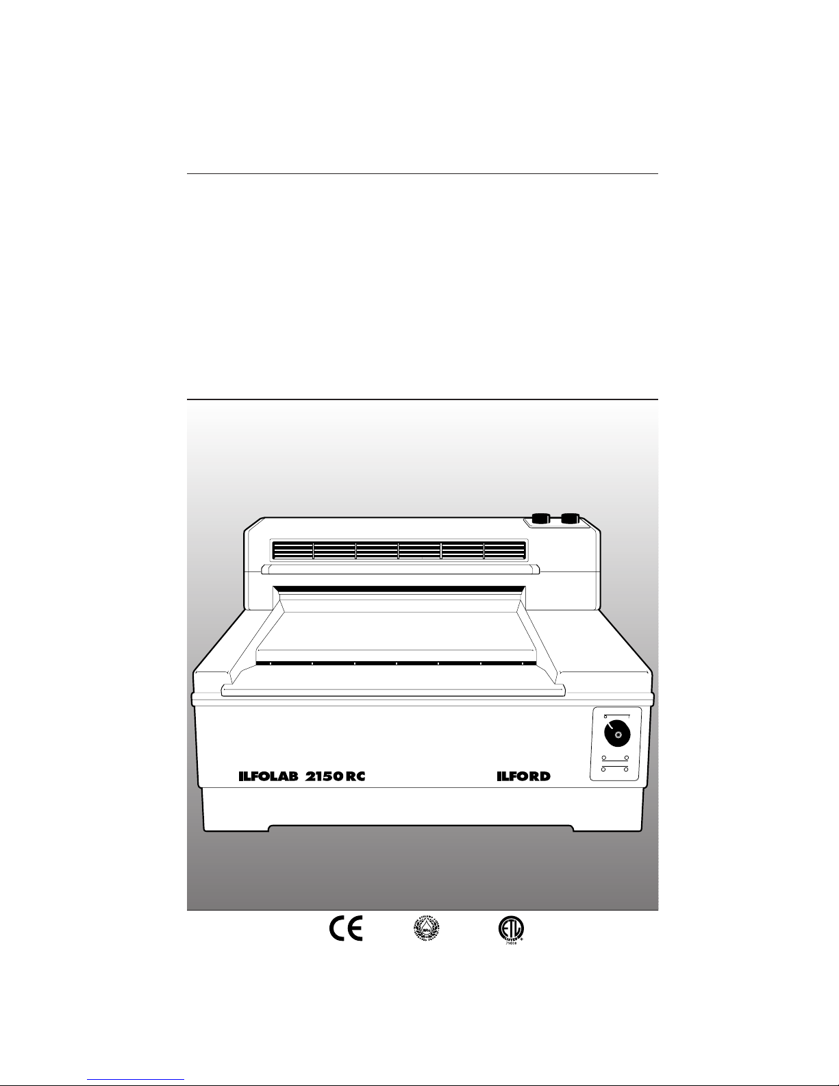
Ilford ILFOLAB 2150RC Operating Manual
IL184A
TABLE TOP AUTOMATIC PROCESSING SYSTEM FOR
HIGH QUALITY BLACK AND WHITE PRINT MAKING
50/60Hz
OPERATING MANUAL
ILFORD
ILFOLAB
2150RC
1st Proof rev A - March 1997
March 1998 - amended BC address/print date/deleted IP logo

1
2
3
4
5
6
7
8
9
10
11
12
13
SAFETY PRECAUTIONS
Your photographic equipment is powered by mains electricity,
and is designed to comply with international electrical safety
standards. However, basic safety precautions must always be
followed when operating electrical equipment, including the
following, where applicable:
Read and understand all instructions and equipment labels.
Close supervision is necessary when the equipment is being used
by inexperienced personnel.
Take care to avoid burns. Some internal parts of the equipment
can become very hot with continuous use.
Do not operate equipment that has been dropped or damaged,
or has damaged electrical leads. Have the equipment examined
by qualified personnel.
Do not allow any electrical lead to touch hot surfaces.
Ensure the leads are arranged such that they cannot be pulled or
tripped over.
Ensure extension leads are of a suitable current rating to prevent
the lead overheating.
Always unplug or isolate the equipment when it is not in use.
Never pull plugs out by holding the lead.
For equipment connected to the electrical mains supply by a plug
and socket arrangement, ensure the socket is installed near to the
equipment and is easily accessible at all times.
Do not touch electrical components with wet or damp hands.
Ensure the air flow through the vents is not obstructed when
equipment is switched on.
Do not dismantle the equipment unless you are qualified to do
so. Incorrect assembly can cause hazards both to yourself and to
the equipment.
All equipment, no matter how well made, can break down and,
therefore, must not be left unattended for long periods of time
while it is switched on.

1415Always unplug or isolate the equipment before connecting or
disconnecting any plugs supplying electrical power to or from the
equipment.
Always obey local codes of practice, particularly for installation
requirements.
Do not destroy these instructions

CONTENTS
1
1.1
2
2.1
2.2
3
3.1
3.1a
3.2
3.3
3.4
3.4a
3.4b
3.5
3.5a
3.6
3.7
4
5
6
7
8
8.1
8.2
8.3
8.4
8.4a
8.4b
8.5
8.6
8.7
8.7a
8.7b
8.8
9
9.1
10
10.1
1
PICTOGRAMS 2
INTRODUCTION 4
Important information 4
CONTROLS AND INDICATORS 6
Processor 6
Dryer 8
INSTALLATION 10
Processor 10
Levelling adjustments 10
Electrical supply 10
Plumbing 10
ILFOLAB 2150RC installation kit (optional) 11
Drain connections 11
Water supply 12
Dryer 12
Removing yellow transit wedges 14
ILFOLAB 2150RC print exit cover assembly 14
Commissioning a new machine 16
ADDING CHEMICALS 18
PROCESSING 19
SWITCHING OFF 21
DRAINING AND RINSING 22
CLEANING AND SIMPLE REPAIRS 24
Daily routine 24
Routine procedure between chemical changes 24
Monthly routine 24
Three monthly routine 24
Processor - cleaning roller racks 24
Dryer - cleaning the four-roller assembly 26
Replacing a mains fuse 27
Resetting the thermal cut-outs 28
Replacing a roller tension spring 28
Processor 28
Dryer 29
Removing dryer rear rollers/adjusting print exit guide 30
FAULT FINDING 33
Safety features 33
SPECIFICATION 40
Recommended processing capacities 43
PICTOGRAMS
The following pictograms are used on labels fixed to the ILFOLAB
2150RC processing system. Please ensure you understand their
meaning.
2
Electrical hazard - refer to manual
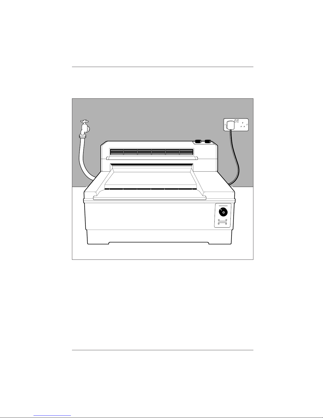
Figure 1.1
ILFOLAB 2150RC processing system - typical installation
ILFORD
OI
ILFOLAB 2150 RC
IL167A
3

1
INTRODUCTION
1.1
4
See figure 1.1.
The ILFOLAB 2150RC table-top processing system is designed for
low to medium volume users of paper. Typically, up to 1000
20˙3x25˙4cm (8x10 inch) prints can be processed on one fill of
chemicals. The system is very easy to install, operate and
maintain, and provides black and white prints on resin coated
papers up to a maximum width of 50.8cm (20 inches). The prints
are fully processed and dried to a very high standard.
This manual gives full instructions for installing and operating the
complete system. By disregarding all references to the dryer, this
manual also describes the processor when used alone.
For ease of description, it is assumed the left and right hand sides
of the processor are determined when facing the processor at the
paper feed (front) end. The left and right hand sides of the dryer
module are determined with the dryer module removed from the
processor and the paper feed side facing (ie the side normally
facing away from the operator). Unless otherwise stated, the
50Hz system is shown.
IMPORTANT INFORMATION
Chemicals
For optimum results always use recommended ILFORD chemicals.
Before handling ILFORD chemicals please ensure you are familiar
with the information detailed in the ILFORD Photochemical Safety
Data Sheets supplied as part of the chemicals pack.
Automatic rinsing
This is a feature designed to simplify regular cleaning operations
and, therefore, to keep major strip-down cleaning to a minimum.
Colour coding
Roller racks are colour coded: red for developer, green for fixer
and white for wash water. Do not interchange the roller racks for
any reason. The same colour coding is used on the drain outlets
at the rear of the processor, the standpipes in the working and
front tanks and the covers on the front tanks.
Operation
A wall chart, which summarises the regular operating procedures,
is supplied with this manual.
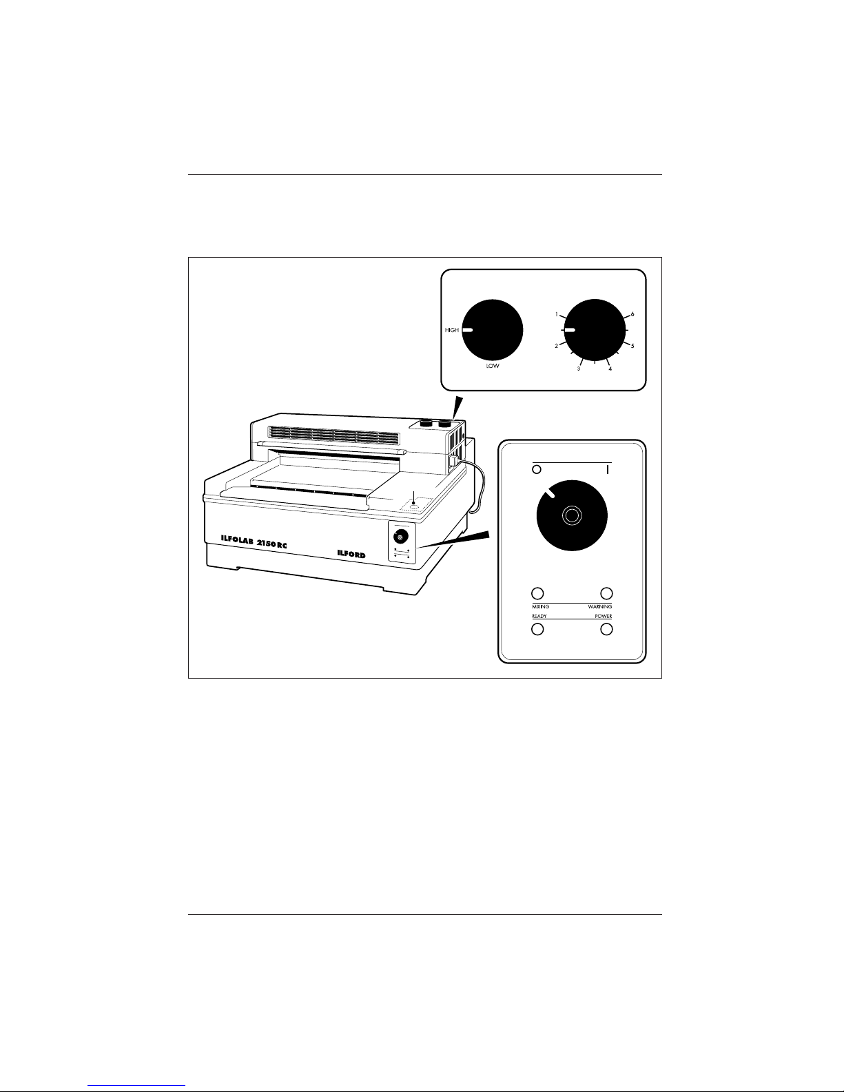
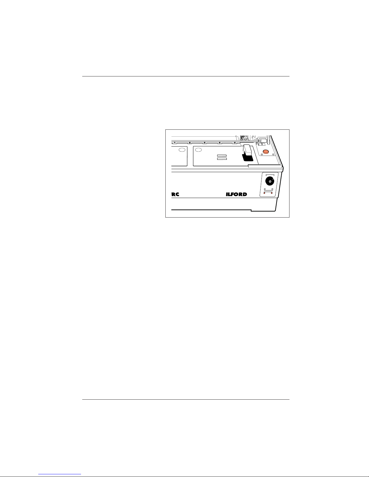
Figure 2.1
Controls and indicators
IL168A
O
I
1
5

2
CONTROLS AND
INDICATORS
2.1
1
2
3
4
5
6
See figure 2.1.
PROCESSOR
Control switch
The control switch has two positions:
Position ‘0’
The processor and dryer are switched off.
Position ‘|’
The processor and dryer are switched on.
‘Mixing’ light
Illuminates when the processor is automatically mixing fresh
chemicals.
‘Ready’ light
Provides two indications:
Flashing
Indicates the system is not ready for use (chemicals are being
mixed or heated).
Steady on
Indicates the system is ready.
Note
The ‘ready’ light switches off when a sheet is fed into the
processor, and switches on when the processor is ready to
accept the next sheet. In this way, the ‘ready’ light serves as a
visual feed indicator, and is synchronised with the audible feed
indicator (see 7 Audible signals).
‘Power’ light
Illuminates when the processor control switch is set to position |’.
‘Warning’ light
Illuminates when the solution level in either of the front tanks is
low. Under normal operating conditions, the levels will not fall
sufficiently for the ‘warning’ light to switch on.
Figure 2.1
Water feed button1
6
7
7
Water feed button
See figure 2.2.
Located on the processor to the right of the front tanks under the
processor lid. The water feed button controls the water supply for
diluting chemical concentrates, and for rinsing the processor.
Audible signals
There are four different signals:
Feed indicator
A single audible signal is made indicating the processor is ready
to accept the next sheet. This signal is synchronised with the
‘ready’ light (see 3 ‘Ready’ light).
Incorrect feed
A continuous audible signal is made lasting the length of a sheet.
This signal indicates that a sheet has been fed before the ‘ready’
light has stopped flashing (see 3 ‘Ready’ light).
Rinsing cycle complete
Three audible signals are made indicating the rinsing cycle is
complete (see section 7).
Warning indicator
A series of audible signals are made. The warning signal sounds
if the processor lid remains open 30 seconds after pressing the
water feed button, or if the solution level in either of the front
tanks is low. If left unchecked, the signal continues for three
minutes and the processor is then automatically switched off.
IL181
Figure 2.2 Water feed button
8
2.2
1
2
8
Thermal cut-out light
See figure 2.3.
Located between the two thermal cut-out resets in the processor
skirt. The light is switched on if either cut-out is tripped.
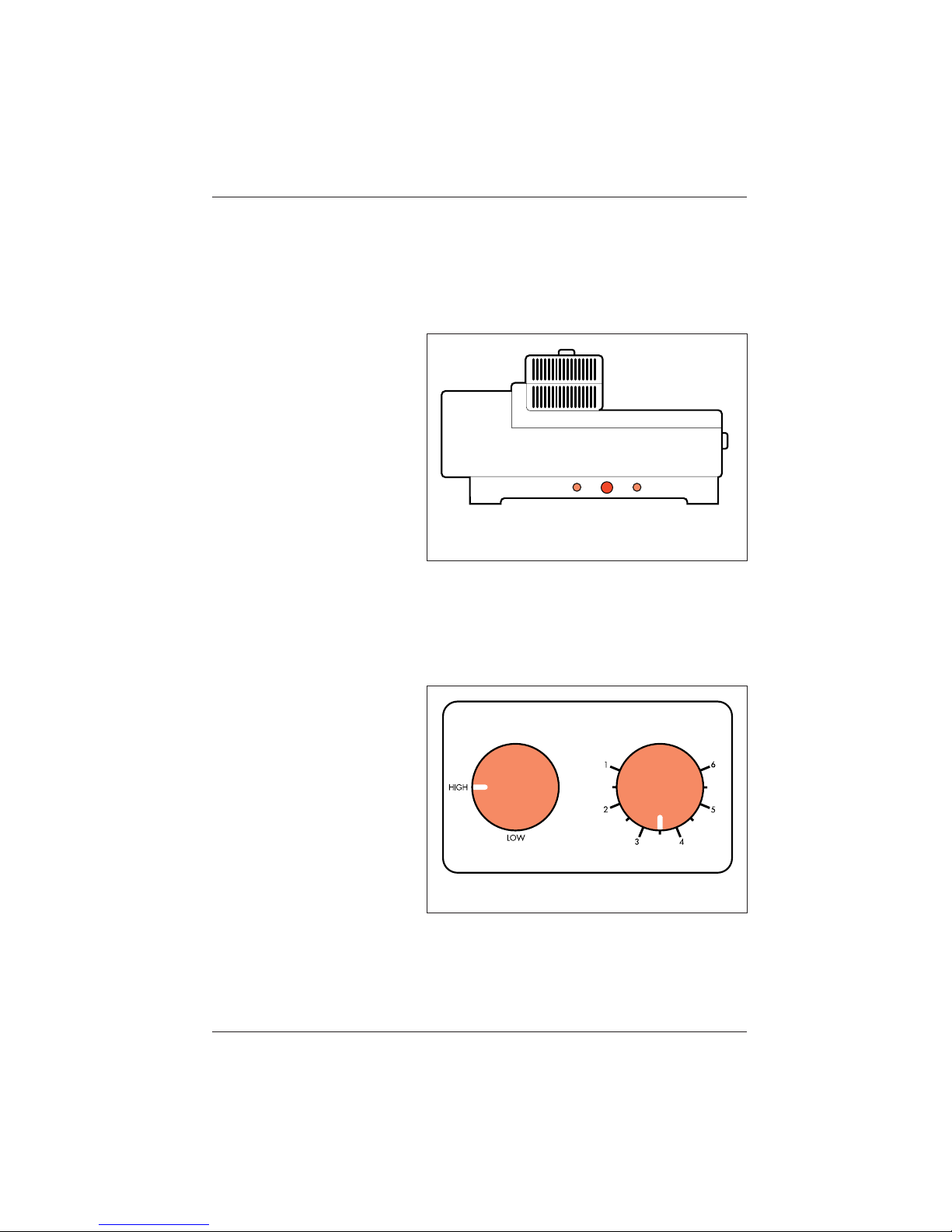
DRYER
See figure 2.4.
Dryer control switch
The dryer control switch has two positions, High and Low.
Temperature control
Adjustable over the range 1 (minimum) to 6 (maximum).
IL185
Figure 2.3 Thermal cut-out
IL186A
Figure 2.4 Dryer controls
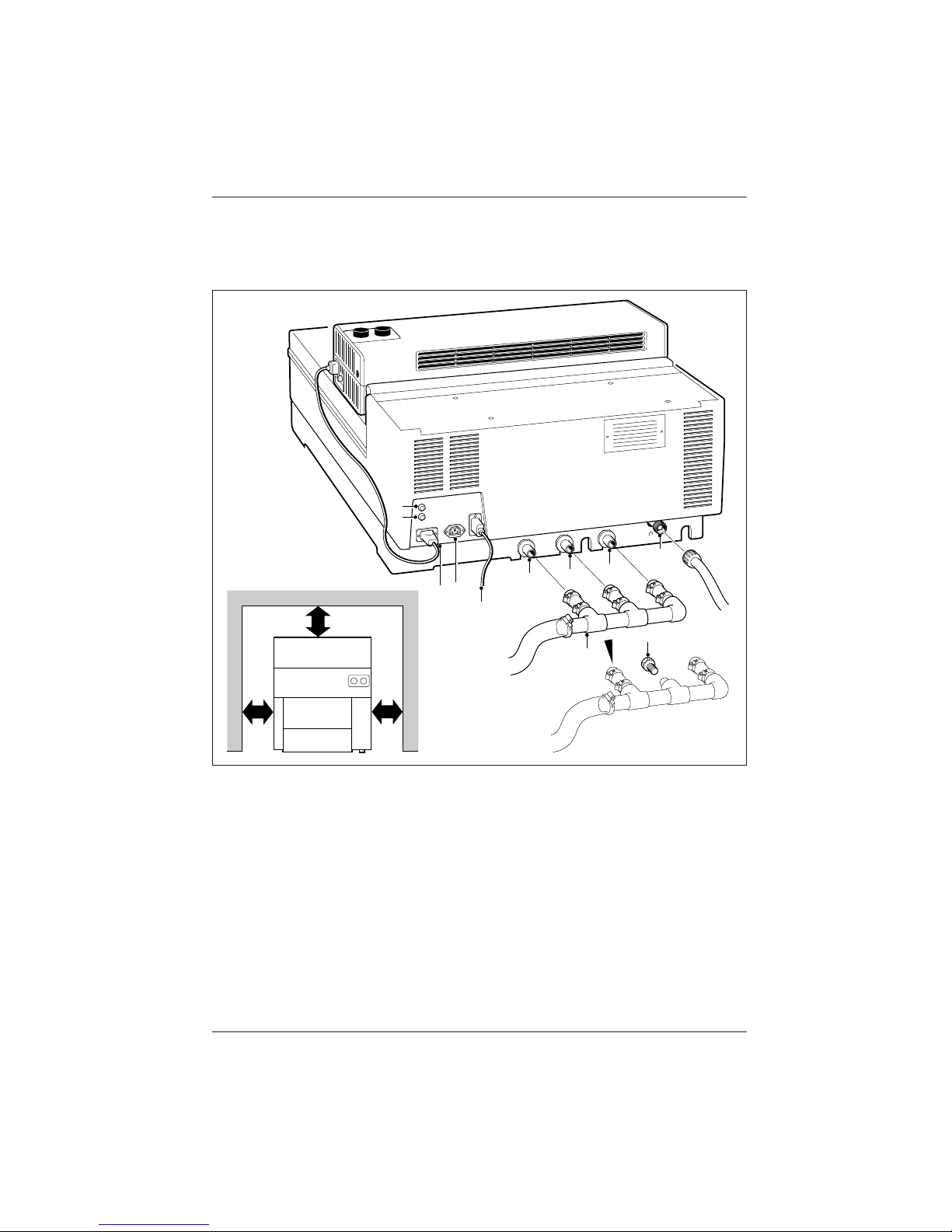
Figure 3.1
Installation - general
150mm
(6in)
150mm
(6in)
150mm
(6in)
IL169A
4
3
5
6
7
8
10
11
2
1
9
9

3
INSTALLATION
3.1
3.1a
3.2
3.3
a
b
10
PROCESSOR
See figure 3.1.
Position the processor on a firm, level bench or table, at a
convenient working height. Leave a space of at least 15cm
(6 inches) between the processor and any wall to allow
adequate air circulation, to ensure the electrical and plumbing
installations are not impeded and to gain access to the thermal
cut-out resets.
Note
The processor lid support can be fitted to either side of the lid to
suit the installation and ease removal of the roller racks.
Levelling adjustments
CAUTION
For correct operation, it is essential to level the processor
accurately.
With the processor positioned, level the processor by placing a
spirit level first along the dividing wall between two of the
working tanks and then along the left and right hand sides of the
processor. Height adjustments are made by turning the four
levelling feet.
ELECTRICAL SUPPLY
See figure 3.1.
Connect the processor to the electrical mains with the lead
supplied. The lead is supplied with plugs, and fits one way only.
60Hz processors only:
The mains supply must be a correctly wired, grounded, 120 volt,
20 amp supply, with a socket suitable to accept the 20 amp plug
fitted to the mains lead. Do not remove the plug from the lead.
PLUMBING
The plumbing can be installed in one of two ways:
By the use of proprietary fittings (see table 3.1 for the dimensions
of the processor connections).
By the use of the ILFOLAB 2150RC installation kit (see section
3.4).
Figure 3.1
Dryer electrical connection
Electrical mains supply to
processor
Processor mains fuse
Dryer supply fuse
Developer drain connection
Fixer drain connection
Wash water drain connection
Wash water supply
connection
Auxiliary power supply
Drain manifold
Blanking plug - fixer drain
1
2
3
4
5
6
7
8
9
10
11

3.4
3.4a
11
Table 3.1 Plumbing connections
Description Dimension
Developer drain (red) connection 21mm
Fixer drain (green) connection 21mm
Wash water drain connection 21mm
Wash water supply connection
3
/
4
inch BSP
ILFOLAB 2150RC INSTALLATION KIT (OPTIONAL)
See figure 3.1.
An installation kit is available as an optional extra to simplify the
plumbing installation. This kit (part number 6171-4-073 or
QY6714073 in North America) is supplied with full fitting
instructions.
There are four connections at the rear of the processor:
Wash water supply;
Wash water drain;
Developer drain (front and working tanks combined);
Fixer drain (front and working tanks combined).
The wash water drain takes the normal excess from the wash
water tank during processing. The wash water standpipe (see
figure 8.1) is fitted for emergency water overflow, and must be
used when draining the tank.
Drain connections
CAUTION
Ensure your drain arrangements comply with local regulations.
The drain manifold supplied with the installation kit has a
maximum of three inlets. These are connected to the processor
drain outlets by the short lengths of flexible pipe.
The fixer drain inlet on the manifold can be sealed using the plug
provided. If it is necessary for the fixer to be drained separately,
fit the blanking plug to the manifold and connect one of the 2m
(6˙5 feet) lengths of flexible pipe supplied to the processor fixer
drain outlet.
Connect the manifold to the service drain with the other 2m
(6˙5 feet) length of flexible pipe. Secure all pipe connections
with the pipe clips supplied.

3.4b
3.5
1
2
3
4
5
12
CAUTION
To prevent air locks and consequential flooding of the wash
water tank, ensure all drains fall continuously to the service
drain.
When using the drain manifold, drain each tank separately and
always drain the fixer before the developer.
Water supply
Note
The processor automatically regulates the flow of water at all
times.
Secure the water pressure pipe supplied to the processor water
supply connection by tightening the outer ring.
If the water supply contains a high proportion of suspended
solids, connect the water supply via a filter unit.
DRYER
See figure 3.2.
Position the dryer on the processor lid, with the paper feed end
of the dryer facing towards the rear of the processor.
Align the holes in the base of the dryer with the holes in the
processor lid.
Carefully open and support the processor lid.
Secure the dryer by inserting the two fixing screws from the
underside of the processor lid.
Plug the dryer into the power socket (marked ‘dryer’) at the rear
of the processor.
WARNING
Do not plug the dryer into any other power supply. The
processor socket is wired via the processor lid interlock, ensuring
the dryer heaters are automatically switched off when the
processor lid is raised.
 Loading...