


Mega Pixel IP Camera
User Manual
For INC-M20xx M13xx Series

II
No part of this manual, including the products and software described in it, may be reproduced, transmitted, transcribed, stored in a retrieval system,
or translated into any language in any form or by any means, except documentation kept by the purchasers for backup purposes, without the express
written permission of ILDVR Digital Technology. (“ILDVR”)
Product warranty or service will not be extended if: (1) the product is repaired, modified, or altered, unless such repair, modification of alteration is
authorized in writing by ILDVR; or (2) the serial number of the product is defaced or missing.
ILDVR PROVIDES THIS MANUAL “AS IS” WITHOUT WARRANTY OF ANY KIND, EITHER EXPRESS OR IMPLIED, INCLUDING BUT NOT LIMITED TO THE
IMPLIED WARRANTIES OR CONDITIONS OF MERCHANTABILITY OR FITNESS FOR A PARTICULAR PURPOSE. IN NO EVENT SHALL ILDVR, ITS
DIRECTORS, OFFICERS, EMPLOYEES OR AGENTS BE LIABLE FOR ANY INDIRECT, SPECIAL, INCIDENTAL, OR CONSEQUENTIAL DAMAGES (INCLUDING
DAMAGES FOR LOSS OF PROFITS, LOSS OF BUSINESS, LOSS OF USE OR DATA, INTERRUPTION OF BUSINESS AND THE LIKE), EVEN IF ILDVR HAS BEEN
ADVISED OR THE POSSIBILITY OF SUCH DAMAGES ARISING FROM ANY DEFECT OR ERROR IN THIS MANUAL OR PRO D UCT.
SPECIFICATIONS AND INFORMATION CONTAINED IN THIS MANUAL ARE FURNISHED FOR INFORMATIONAL USE ONLY, AND ARE SUBJECT TO CHANGE
AT ANY TIME WITHOUT NOTICE, AND SHOULD NOT BE CONSTRUED AS A COMMITMENT BY ILDVR. INACCURACIES THAT MAY APPEAR IN THIS
MANUAL, INCLUDING THE PRODUCTS AND SOFTWARE DESCRIBED IN IT.
Products and corporate names appearing in this manual may or may not be registered trademarks or copyrights of their respective companies, and
are used only for identification or explanation and to the owners’ benefit, without intent to infringe.
Copyright © 2011 ILDVR DIGITAL TECHNOLOGY all rights reserved.

III
To contact us:
Headquarter: www.ildvr.com
Branches
Europe: www.ildvr.eu
Russia:
www.ildvrcom.ru
ILDVR Global Distribution & Service
Germany: www.ildvr.de
Italy:
www.ildvr.it
Netherland:
www.ildvr.nl
Russia:
www.il-dvr.ru, www.ildvr-video.ru
Ukraine:
www.ildvr.com.ua

IV
Contents
1. SEARCH IP ADDRESS AND INSTALL ACTIVEX ................................................................................................................................. ……………………………………………............5
2. LOGIN
............................................................................................................................................................................................................................................................................ 6
3. SYSTEM MAIN INTERFACE
............................................................................................................................................................................................................................................ 7
4. PLAYBACK
...................................................................................................................................................................................................................................................................... 9
5. INC-M20XX SYSTEM SETTINGS
................................................................................................................................................................................................................................... 12
5.1
SYSTEM .................................................................................................................................................................................................................................................................... IV
5.2
USER MANAGEMENT ................................................................................................................................................................................................................................................. 13
5.3
NETWORK SETTINGS ................................................................................................................................................................................................................................................... 13
5.3.1 Basic Settings
................................................................................................................................................................................................................................................. 14
5.3.2 Advanced Settings
......................................................................................................................................................................................................................................... 15
5.4
VIDEO SETTINGS ........................................................................................................................................................................................................................................................ 19
5.5
AUDIO SETTINGS ....................................................................................................................................................................................................................................................... 20
5.6
ALARM SETTINGS ...................................................................................................................................................................................................................................................... 21
5.6.1 Motion Alarm
................................................................................................................................................................................................................................................ 21
5.6.2 Video Loss Alarm
........................................................................................................................................................................................................................................... 22
5.6.3 Sensor Alarm
................................................................................................................................................................................................................................................. 23
5.6.4 Network Failure
............................................................................................................................................................................................................................................. 25
5.7
STORAGE SETTINGS .................................................................................................................................................................................................................................................... 26
5.7.1 Device Management ..................................................................................................................................................................................................................................... 26
5.7.2 Record Schedule
............................................................................................................................................................................................................................................ 27
5.7.3 Snap Schedule
................................................................................................................................................................................................................................................ 27
5.8
COM SETTINGS ......................................................................................................................................................................................................................................................... 28
5.9
LOCAL SETTINGS ........................................................................................................................................................................................................................................................ 29
APPENDIX 1 NETWORK INTERFACE FOR INC-M20XX
..................................................................................................................................................................................................... 30
APPENDIX 2 DEFAULT NETWORK PARAMETERS
.............................................................................................................................................................................................................. 2
APPENDIX 3 APPLY FOR DDNS DOMAIN NAME SERVICE
................................................................................................................................................................................................. 2
APPENDIX 4 VISITS INC-M20XX UNDER DIFFERENT NETWORK ENVIRONMENTS
.......................................................................................................................................................... 6
APPENDIX 5 FAQ ............................................................................................................................................................................................................................................................. 10
5
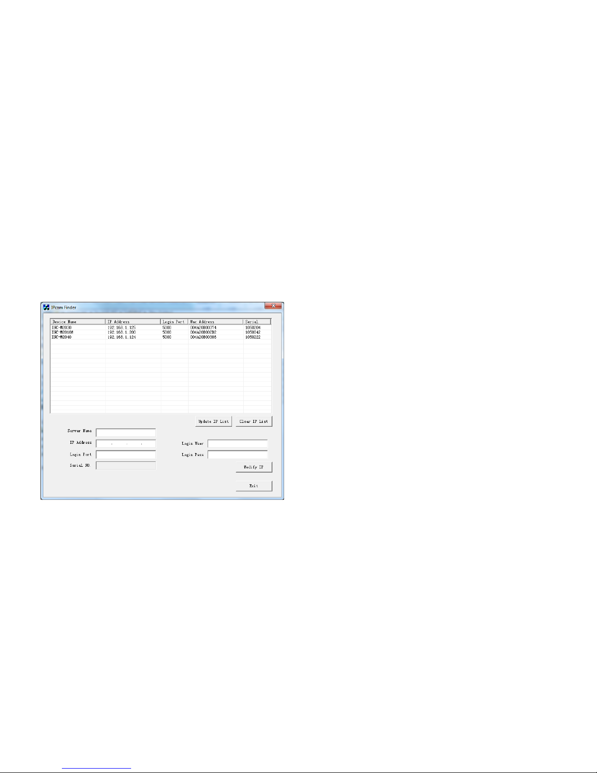
1. Search IP Address and Install ActiveX
If you cannot find camera’s IP address, please use IPcam Finder software to search. You can find this program i n Hybrid DVR Ser ver or Live Center installation program folder.
Modify IP address: select device name, input new IP address, remember to input login user and login pass, click modify IP to save.
Rename IP camera: Configure->Remote Confi g->System-> System Info->Device Name
Rename OSD name: Configure->Remote Config->Video Settings - >text overlay->T itle
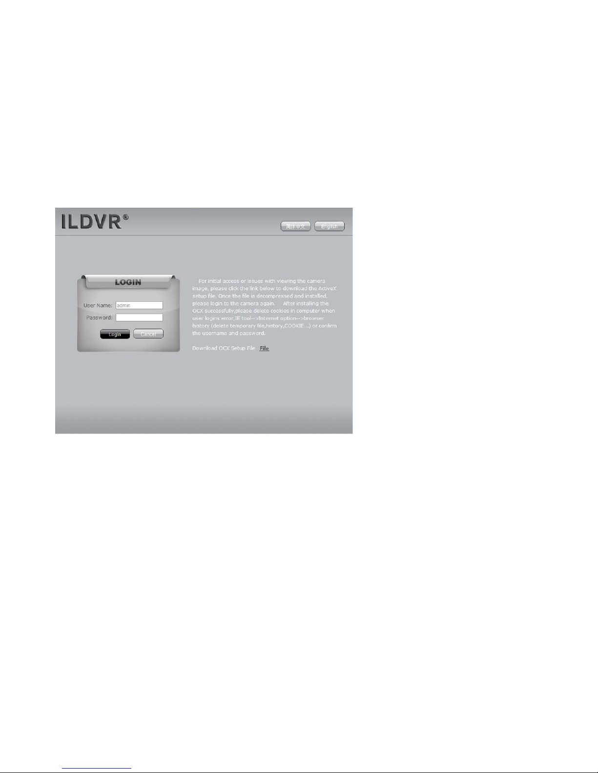
You need to install ActiveX Control when you visit INC-M 20xx for the first time through IE browser.
ActiveX installing method:
Input the IP address of the INC- M20xx into the address bar of Internet Explore to enter into login page, for example, enter 192.168.1 .200.
Click [File] to download the ActiveX:

6
A new dialogue box appears, click [Run] or [Save] to download ActiveX, a nd then doubl e-click the downloaded fil e “xdview.exe” to install it, see below picture:
Close current Internet Explorer, click “Install” bu tton,the ActiveX will be automatically installed. After installation finishes, a dialo g box with the message “Register OCX success!” will pop up.
2. Login
Open Internet Explorer, and input the IP address of INC-M 20xx, enter into login page as follow. Input User name (Default: admin), Password (Default: admin), click “login” to enter into the
main interface.
Default Factory:
IP: 192.168.1.200
User Name: admin
Password: admin
7
3. System Main Interface
See below for the system main interface:

8
In the Liveview interface, users can do operations like Snapping, Recording , Playback, Talkback, Monitoring, Clear Alarm, Log Search, Partial Zoom-in of Image, Full-screen Viewing,
Lightness and Color Adjustment and Lens Control.
[Snap]: click to snap an image and save it automatically in the storage directory of system settings.
[Record]: Manually record video and save it to the storage directory of system settings.
[Playbac k]:
Click “Playback”, the playback page will pop up for searching and playback of recorded files or snapped images.

9
[Call] : After switch on the audio talkback switch, the ta lkback between PC and INC- M20xx can be performed given that audio talkback device is installed to the INC-M 20xx.
[Listen]:
After switch o n the monitori ng switc h, PC can monitor the sound at the device end.
[Alarm]: When there is an alarm, double-click [Alarm] to cancel the alarm manually.
[Log]: Users can search for operations and alarm logs, th e maximum capacity is 512 entries of message, whe n the number of entries exceeds 512, and system will delete records of
the earliest date automatically.
[Zoom In]: This feature allows the manual drag and drop of video display area to realize partial zoom in.
[Full Screen]: Allows full-screen video display, right click to exit full screen mode.
[Image Color]: Adjust ima ge brightness, contrast, hue and saturation. See the picture at the left below:
[PTZ Control]: Allows PTZ operations like Zoom, Focus, Aperture, Light, Brush, Preset, and Recall, see the picture at the right below:
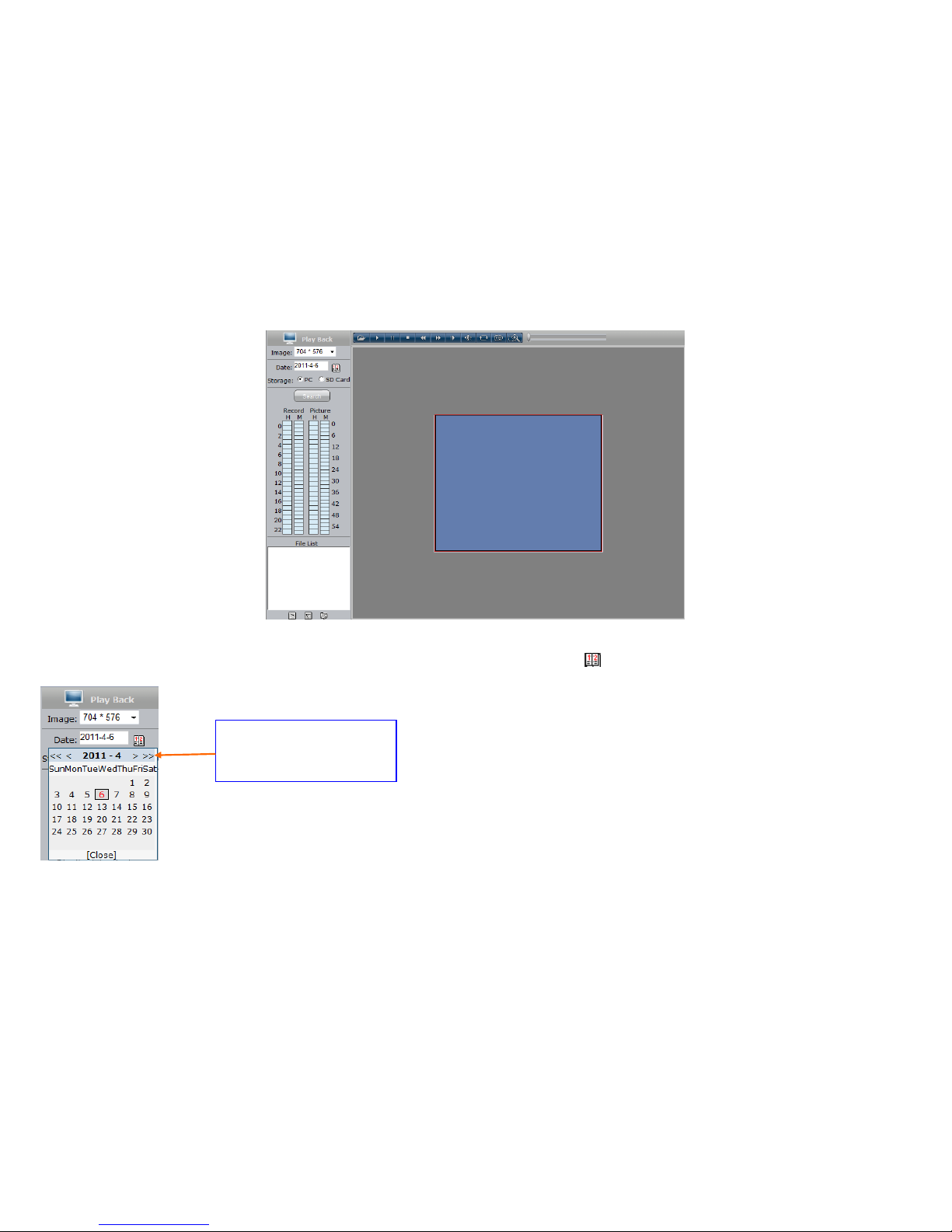
4. Playback
Click [Playback] button to enter into video playback page as follow:
10
Users can search recorded image files or snapped pictures in local PC or storage device according to date.
[Image]: Users can choose the desired definition for playback. When selected definition exceeds display definit ion, it should be scaled accordingly.
[Date]: Users can select certain date to perform recorded image file or snapped picture searching, click “date” button ,
The calendar page will pop up as below:
Selecting a specific date will be au tomatically shut down the calendar page, if you want to display the current default date, please choose [Close] to close the calendar page.
[Local]: Users can select certain date to perform recorded image file or snapped picture searching.
Click “《 ”icon to go to pr evious year
Click “ 》”ic on to go to next year
Click “〈 ”icon to go to previous month
Click “ 〉”icon to go to next month
11
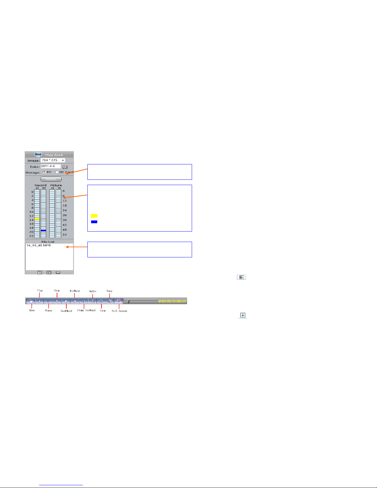
[Device]: Users can select certain date to search for recorded image files or snapped pictures in storage device.
[File List]: Shows the recorded image files or snapped pictures searched in the File List.
The way to search for recorded image files or snapped pictures of a specific period:
[Play]: Choose the recorded image or snapped picture in file list, right click the file or picture or click “play” button to play. The contents wi ll be displayed in the rig ht window,
users can view the playing information and control the process, see below picture:
[Download]: Select the recorded files or snapped pictures searched from SD card in the file list, click “download” button to download the fi les to PC.
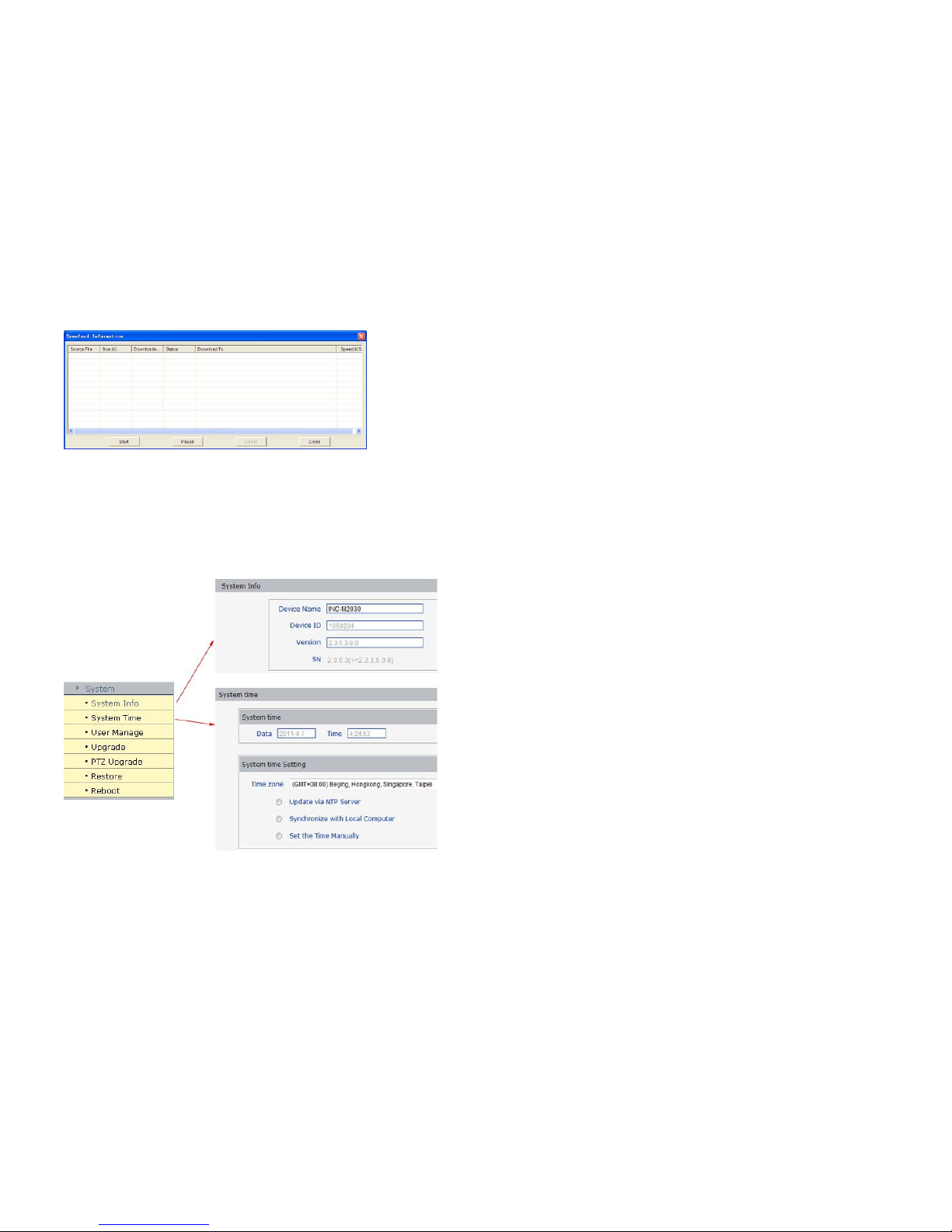
[Download information]: Users can view the information downloaded after clicking “Download”, see below picture:
The list of recorded files searched displays on the left
The list of snapped pictures searched displays on the right
The hour range is on the left, each grid stands for 1 hour.
The minute range is on the left, each grid stands for 1
minute
: Selected time range
: Recorded files or snapped pictures exist within the
time range
Select to search for recorded files and snapped pictures in PC or
storage device
Display the recorded files or snapped pictures searched within the
selected time range
12
Click [Pause] to pause download manually, click [Start] to continue to download the unfinished fi les, click [Delete] to delete the downloaded files, click [Close] to close the download
information interface.
5. INC-M20XX System Settings
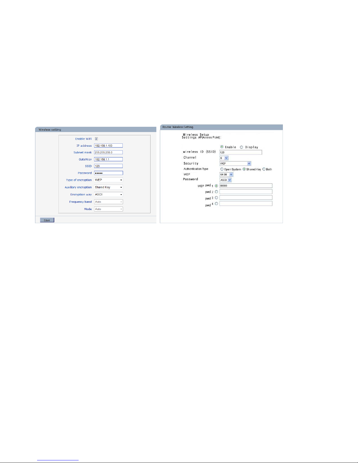
5.1 System
Below picture is the system settings page of INC-M20xx:
[System Time]: set date and ti me for INC- M20xx, click “synchronize with PC” to synchronize the date and time of INC- M20XX with those of the PC.
[System Information]: Display device name, device number and video mode. The device name can be us er-defined. Two video modes: PAL and NTSC.

13
[System time Settings]: when starting NTP function, INC-M20 xx will correct the INC-M20xx system clock on NTP server regularly according to its setting.
[Upgrade]: Click “Browse…” button, and select correct file of upgrade (kernel file, suffix.uot), click [upgrade], then you can upgrade your system, the completion rate will be displayed during
this process. After completion, INC-M20xx will restart a utomatically. Re-log in device, enter into system settings page, check to see whether the kernel edition is the upgraded edition.
Note: Don’t cut off the power and internet connection when upgrading.
[Restore]:All INC-M 20xx parameters (excluding physical address) wi ll be recovered as factory setting values.
Note: Please use t his function with caution!
[Reboot]: Click [Reboot], the INC-M20xx will restart automatically.
5.2 User Management
Below picture is the “user management settings” page of INC-M20xx:
You can set three users for every INC-M 20xx, one is Administrator, a nd the others are general users. Administrator can set parameters for the INC-M20xx. However, Guest cannot set parameters for
INC-M20xx.
Note: Use r name and password must be 1-16-character-strings consisted by letters, numbers, underlines or dots. The Characters are case sensitive.
5.3 Network Settings
Default Administrator Name: admin password: admin
Default Guest1 Name: guest 1 password: guest1
Default Guest2 Name: guest 2 password: guest2
Note: User name and password are case-sensitive

14
5.3.1 Basic Settings
Below picture is the “network settings” pa ge of INC- M20xx:
[Basic Parameters]
IP Address: Set the device IP of INC- M20xx
Subnet mask: default value is 255.255.255.0 (users are recommended not to change it)
Gateway: Set the gateway IP of INC- M20xx, for example when the device is connected to WAN via a router, the gateway IP is the router IP.
MAC: the MAC address of INC-M20xx (users are recommended not to change it).
Data port: default value is 5000 (users a re recommended not to change it).
Web port: default value is 80 (users are recommended not to change it).
Multi-cast IP: send the IP address of multi-cast data. The range is 224.0.0.0~239.255.255.255.
Multi-cast port: default value is 5000 (users are recommended not to change it).
DNS address: Set the DNS address as your local DNS address.
Note: after revise and save parameters, the device w ill restart. If it is applied in L AN, please pay attention to avoid conflict between its IP address and the IP addresses of other devices or PC
in the LAN.
[Wireless network transmission mode]
Enable or disable wireless network transmission mode which applies to devices that are connected to wireless network of carriers.
[DDNS setting]
Bind the device with a fixed domain name by DNNS setting so that visiting to the device can be realized no matter how the public IP changes.(refer to Appendix 3 for detailed steps)
DDNS On/Off: enable or disable DDNS function.
DDNS User Name: User registered in DDNS server.
DDNS Password: User password registered in DDNS server.

15
DDNS Domain Name: The Domain Name set for long-distance access after user log in.
DDNS Address: DDNS server address. When DDNS address is the domain Name, please set the DNS address in [Basic Parameters] c or rectl y.
DDNS Port: Default is 30000
Data Mapping Port: When INC-M20xx is mapped to public network via router, fill in the public data port number after mapping.
Web Mapping Port: When INC-M 20xx is mapped to public network via router, fill in the public web port number after mapping.
[PPPOE setting]
PPPOE switch: enable or disable PPPOE dial-up functio n.
PPPOE address: after successful setting of device dial- up, it will display the public IP Address.
PPPOE user name: ADSL dial-up account, obtain from the IP ser vice provider.
PPPOE password: ADSL dial-up password, obtain from the IP ser vice provider.
On-line duration: start timing after dial-up to see the online duration after successful dial-up.
After setting all the pa rameters, click [save] to make the parameters val id.
5.3.2 Advanced Settings
[Mail setting]
To set the mail box addresses and parameters of alarm mails and WAN IP mails.
SMTP server: the address of servers that send the mails, the address format of mail serv ers varies from provider to provider, e.g. the SMTP server of 163 mailboxes is smtp.163.com.
Mail sending address: mailbox that sends mails.
Mail receiving address: mailbox that rec eives mails.
SMTP user name: the login user name of the mailbox that sends mails.
SMTP password: the login pa ssword of the mailbox tha t sends mails.
Mail title: title of mails.
SMTP Port: port of SMTP po rt, different mail server has different port. For example, the server port of Gmail is 465.
Commonly used mail server configuration:
Gmail mail server:
SMTP server: smtp.gmail.com
SMTP user name: username@gmail.com
SMTP port: 465
SSL: enabled
Yahoo mail server:
SMTP server: smtp.mail.yahoo.com
SMTP user name: username@yahoo.com or username@yahoo.com.cn

16
SMTP port: 465
SSL: enabled
163 mail server:
SMTP server: smtp.163.com
SMTP user name: username
SMTP port: 25
SSL: disabled
[FTP setting]
FTP server sends the record files and snapped images generated after alarm has been triggered in FTP mode to specified FTP server, supports 2 FTP servers, when the preferred one goes
wrong, system w ill switch to the alternate o ne.
FTP URL: the IP address or HTTP address of FTP server.
FTP port: port of FTP server, the default port is 21.
Remote path: path on remote FTP server, if the path doesn’t exist or has not been filled in, the devic e will create a file folder under the root directory of FTP server.
FTP user name and password: user name and password of FTP s erver.
Note: Users must have the authority to writ e on the FTP server in order to upload record files and snapped images.
[Directional Sending]
Target IP: set the target IP address.
Port: set the port of target IP address.
On/Off: se nding data packet to specified IP address and port or not.
[Public IP mail notification]
Mail notification on/off: enable or disable public IP mai l notification function.
Interval: select the interval of public IP mail notifications.
After enable this function, when INC-M20xx starts or detects public IP change, it will send notification mail to the mail address set in “mail setting”.
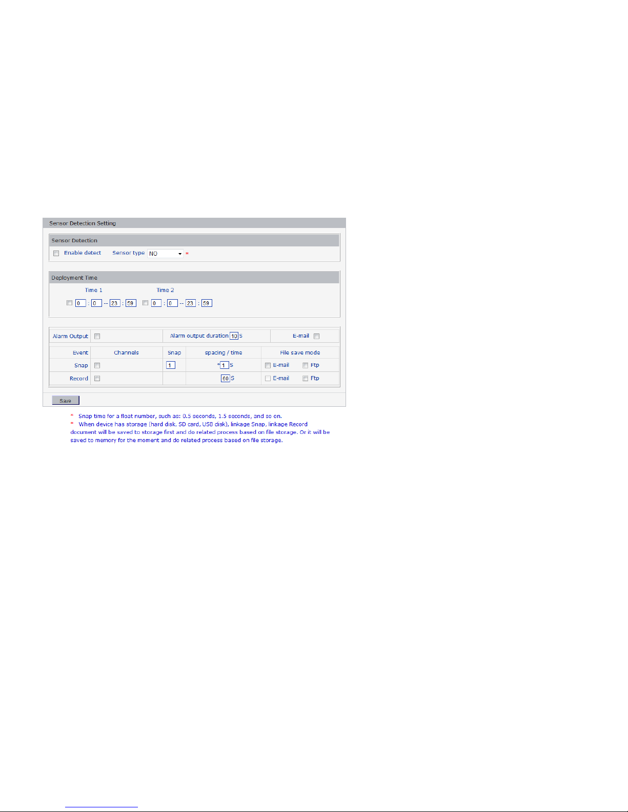
[Wi- Fi setting]
Note: applies to models with Wi- Fi function only.
A wireless router needs to be deployed in order to use the Wi- Fi function of INC- M20xx.
1 Network parameters setup for wireless router
First enter into the wireless router “network parameter” page under the menu “LAN Setting ”, set the IP of wireless router
17
2 Turn to the “basic setting” page under “wireless parameters” menu,
(1) Set SSID:
This SSID is for identity authentication of wireless network, it must be the same as the SSID setting of the INC-M20xx.
(2) Frequency range
It determines the frequency range of the network, which is 1~13, default value is 6.
Note: If your neighbor also uses wireless network and its frequency is 6, you should consider revise this parameter to 1 or 13 to reduce radio interference between the two routers.
(3) Mode
Set the working mode of wireless router. The mode must be compatible with the supported modes of INC-M20xx.
Wireless mode supported by INC-M20xx: 802.11b/g protocol (small power Wi-Fi model)
802.11a/b/g/n protocol (high power Wi-Fi model)
(4) Enable Wi- Fi function (compulsory)
(5) Enable security setting (optional)
This option can enable the s ecurity certif ication of wireless router. If it is enabled, us ers need to select the correspondin g security mo de (encryption mode) and set up aut hentication
password.
(6) Select security type (encryption mode)
WEP, WPA and WPA2
(7) Security options

18
WEP security type: developing system, sharing key and auto-selection
WPA, WPA2 security type: TKIP and AES
(8) Set key (authentication key)
123 is the login SSID number of Wi-F i for identity authentication
Check this option to enable W i-Fi function
Security setting is the password for identity authentication; the password is empty if this option is not checked
3 The Wi- Fi function settings of INC-M20xx:
(1) Wireless network on/off
Select this switch will enabl e Wi- Fi function of INC- M20xx.
(2) IP address
Set the wireless IP address of INC-M20xx, e.g. 192.168.1.160.
(3) Gateway
Set the IP address of c urrent wireless gateway, e.g. 192.168.1.1.
(4) SSID number:
It is the login name of Wi-Fi for identity a uthentication; it must be the same as the SSID number of the wireless router (e.g. 123).
(5) Password
It is the login name of Wi-Fi for identity authentication; it must be the sa me as the key of the wi reless gateway (router/AP).
(6) Master authentication encryption type
Three encryption types are WEP, WPA and WPA2. Its selection must be the same as the security type setting of wireless gateway (router/AP).
(7) Auxiliary encryption mode
WEP encryption type: developing system, sharing key and auto-selection;
WPA, WPA2 encryption type: TKIP and AES
It must be the same as the security option setting of wireless gateway (router/AP).
After setting completes, save all parameters. Then disconnect the network cable, INC- M20xx can be visited via wireless IP, such as 192.168.1.160.
Note:
The wireless network IP address and cable network IP address cannot be in the same segment.
The Wi- Fi switch appears to be grey w hen INC-M20xx doesn't have Wi- Fi function.
[UPNP setting]
Auto mapping of port, when there is server with UPNP func tion in the LAN, server will map the port to WAN automa tically upo n starting of this function.

19
UPNP NIC: the type of NIC connecting UPNP server.
UPNP Mode: specified mode a nd auto mode:
Specified mode means to sp ecify data ma pping port an d web mapping port to server.
Auto mode means data mapping port and web mapping port are set up by server.
UPNP server: gateway address of IP server with UPNP function.
[RTSP setting]: check RTSP switch to enable RTSP function, the default RTSP port is 554.
After setting all t he parameters, click [save] to make the parameters valid.
5.4 Video Settings
Below picture is the “Video Coding ” page of INC- M20xx:
In here, refer to some words need to explain.
[Coding]: Select H.264 or MJPEG com press.
[Definition]: set definition of images, modes supported are:
PAL mode – four definitions formats: D1 (704*576)/Half- D1 (704*288)/CIF (352*288)/QCIF (176*144)
NTSC mode – four definitions formats: D1 (704*480)/Half-D1 (704*240)/CI F (352*240)/QCIF (176*120).
[Image Quality]: users ca n choose the right quality according to thei r needs: Best, Good, Normal, and the parameters can also be user-defined by checking [advanced settings] checkbox.
[I frame interval]: adjustable between 5~200.Smaller I frame interval means higher image bit -rate and better image quality. It is recommended to set the frame interval as above 25.
[Frame Rate]: set encoding frame rate per second. Under po or network condit ion, frame rate can be reduced to control encoding bit- rate to make motion images flow more smoothly.

20
[Rate control]: CBR and VBR are optional. CBR adopts constant encoding bit- rate; VBR adopts variable encoding bit-rate.
[Bit-rate]: the range of preferre d and alternat e stream is 30~1 6384Kbps.Higher bit-rate setting can generate better image quality, but it occupies more bandwidth, please adjust the setting
according to your actual bandwidth.
Under CBR setting, [B it-rate] is the constant bit-rate of encoding.
Under VBR setting, [Bit-rate] is the variable bit- rate of encoding.
[Image quality]: Under CBR setting, bit- rate range is set via [Image quality], 1 means that bit- rate range is control by the software, 2~6 stands for a bit-rat e range of ±10% ~±50%
Under VBR setting: set image quality via “Image Quality”, smaller value of image quality means better quality and higher bit-rate, but the bit-rate will not exceed its set value.
[LAN default value]: I frame interval: 100, frame rate: 25, bit-rate: VBR, 2048kbps, image quality: 2
[WAN default value]: I frame interval: 25, frame rate: 5, bit-rate: CBR, 384kbps, image quality: 4
Note: Non-professio nal users please use “Advanced Settings” with caution
[Video Masking O n/Off]: enable or disable vi deo masking.
[Mask Area Setup]: right click and move cursor to set image masking area, an image can be entirely or partially masked, maximum 4 areas supported.
[All]: mask the whole image.
[Clear]: clear masked areas.
[Parameter setup for snapping function]: supports only images of JPG format currently, definition is the same as set in [video definition].
After setting all the pa rameters, click [save] to make the parameters val id.
5.5 Audio Settings
See below picture for “INC-M20xx Audio Settings”:
[Input type]: select your audio de vice input type mic or line i n.

21
[Type]: select audio compress type.
[Audio on/off]: open or close the audio of INC-M20xx. After switch on this switch, PC can monitor the sound at the device end.
Note: 1 when there is no need for audio, close audio input to save network resource.
2 audio is disabled by default.
[Sampling rate]: Supports sample rates of 8k and 32k.
After setting all the pa rameters, click [save] to make the parameters val id.
5.6 Alarm Settings
5.6.1 Motion Alarm
Below picture is the “motion alarm settings” page of INC- M20xx:
In here, refer to some words need to explain.

22
In this page, users can set features like motion detection on/off, sensitivity, detection time, linkage alarm output, linkage output duration, E-mail sending after alarm has been triggered,
linkage device s napping/snapping, etc.
[Detection On/Off]: open or close mot ion detection.
[Sensitivity]: set the sensitivity of motion detection, its range is 1~5, greater value means higher sensitivity.
[Motion detectio n time setup]: set the period of motion detection. Any period in each day can be set up.
[Linkage alarm o utput]: When alarm is trig gered, the built-in relays will be driven to output alarm.
[Alarm Output Duration]: Set the duration of the linkage alarm output after being triggered (in seconds), the range of the duration is 0~86400s.0 means that there is no limit for al arm output.
[E-mail sending]: Send motion detection alarm information to users via E-mail, details about E-mail setting please refer to [Network Settings].
[Linkage Snapping]: Drive device snapping after alarm has been triggered, and save pictures to devi ce HDD. For snapping parameters, if the number of pictures snapped at one time is set as 5, and the snapping
interval is 1 second, that means when there is an alarm, 5 pictures will be snapped and the interval between each picture is 1 second. The pictures snapped can be saved via E-mail sending or FTP uploading.
[Linkage Recording]: Drive device recording after alarm has been triggered, and save record files to device HDD. The record files can be saved via FTP uploading.
Note: Record packing duration= Alarm duration + duration set in linkage recording parameters.
[Set detective a rea]: left click and drive the mouse to set the surveillanc e areas (4 area s at most).
[All]: set the whole vi deo as motion detec tion area.
[Clear]: clear all motion detection area.
After setting all the pa rameters, click [save] to make the parameters val id.
5.6.2 Video Loss Alarm
Below picture is the “ Video Loss Alarm” page of INC-M20xx:

23
In here, refer to some words need to explain.
In this page, users can set features like video loss detection on/off, linkage alarm output, linkage o utput duration, E-mail sending after alarm has been triggered, linkage device
snapping/snapping, etc.
[Detection On/Off]: open or close vi deo loss detection.
[Linkage alarm o utput]: When alarm is trig gered, the built-in relays will be driven to output alarm.
[Alarm Output Duration]: Set the duration of the linkage alarm output after being triggered (in seconds), the range of the duration is 0~86400s.
0 means that there is no limit for alarm output.
[E-mail sending]: Send video loss detection alarm information to users via E-mail, details about E-mail setting please refer to [Network Settings].
[Linkage Snapping]: Drive device snapping after alarm has been triggered, and save pictures to device HDD. For snappin g parameters, if the number of pictures snapped at one time is set as 5, and the snapping
interval is 1 second, that means when th ere is an alarm, 5 pictures will be snapped and the interval between each picture is 1 second. The pictures snapped can be saved via E-mail sending or FTP uploading.
[Linkage Recording]: Drive device recording after alarm has been triggered, and save record files to device HDD. The record files can be saved via FTP uploading.
Note: Record packing duration= Alarm duration + duration set in linkage recording parameters.
[Set detective a rea]: left click and drive the mouse to set the surveillanc e areas (4 area s at most).
[All]: set the whole video as v ideo loss detec tion area.
[Clear]: clear all video loss detection area.
After setting all the pa rameters, click [save] to make the parameters val id.
5.6.3 Sensor Alarm
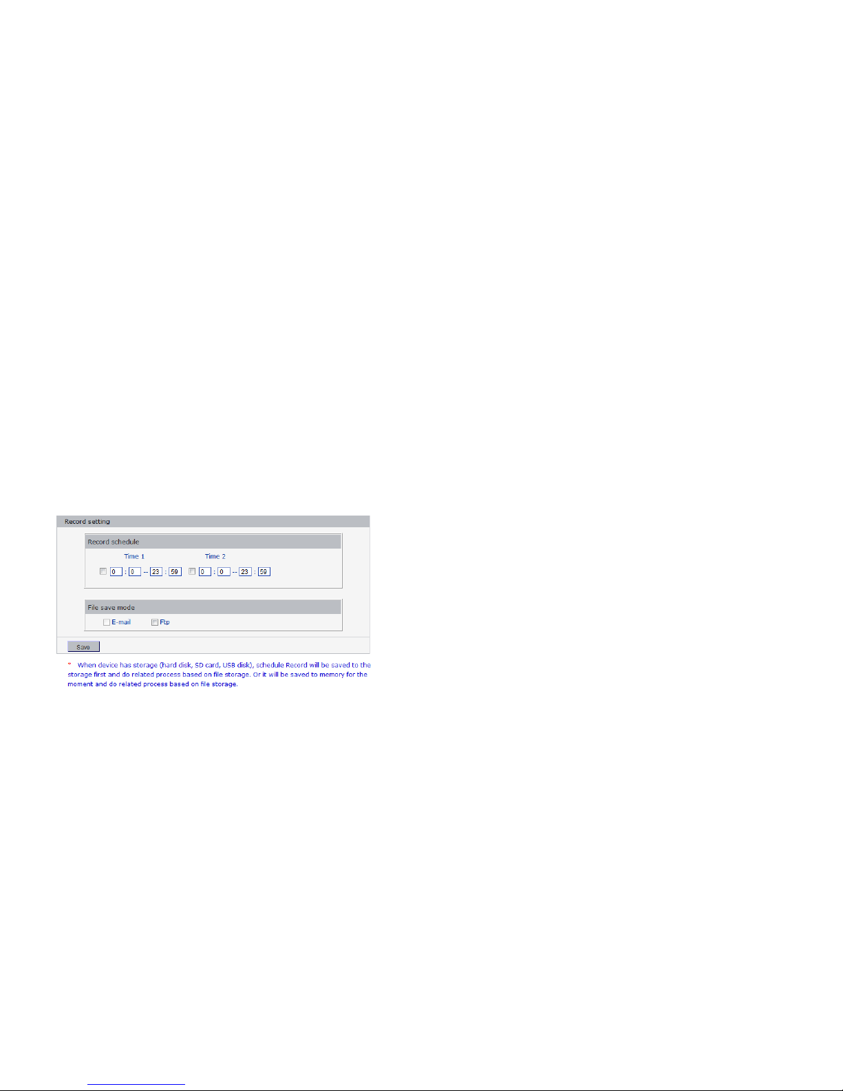
Below picture is the “sensor alarm settings” page of INC-M20xx:
24
In this page, users can set features like sensor alarm detection on/o ff, sensor ty pe, detection time, linkag e alarm output, linkage output duration, E-mail sending after alarm has been
triggered, linkage device snapping/snapping, etc.
[Detection On/Off]: open or close sensor alarm detection.
[Sensor mode]: NO and NC mode.
[Detection time setup]: set the time period of motion detectio n. Any period in each day can be set up.
[Linkage alarm o utput]: When alarm is trig gered, the built-in relays will be driven to output alarm.
[Alarm Output Duration]: Set the duration of the linkage alarm output after being triggered (in seconds), the range of the duration is 0~86400s.0 means that there is no limit for alarm output.
[E-mail sending]: Send video loss detection alarm information to users via E-mail, details about E-mail setting please refer to [Network Settings].
[Linkage Snapping]: Drive device snapping after alarm has been triggered, and save pictures to device HDD. For snapping parameters, if the number of pictures snapped at one time is set as 5, and the snapping
interval is 1 second, that means when there is an alarm, 5 pictures will be snapped and the interval between each picture is 1 second. The pictures snapped can be saved via E-mail sending or FTP uploading.
[Linkage Recording]: Drive device recording after alarm has been triggered, and save record files to device HDD. The record files can be saved via FTP uploading.
Note: Record packing duration= Alarm duration + duration set in linkage recording parameters.

25
[Set detective a rea]: left clic k and drive the mouse to set the surveillanc e areas (4 areas at most).
[All]: set the whole vi deo as motion detection area.
[Clear]: clear all motion detection area.
After setting all the pa rameters, click [save] to make the parameters val id.
5.6.4 Network Failure
Below picture is the “network failure alarm settin gs” page of INC- M20xx:
In this page, users can set features like network failure detection on/off, linkage alarm output, linkage output duration, E-mail sending after alarm is triggered, linka ge device
snapping/snapping, etc.
[Detection On/Off]: open or close network failure alarm detection.
[Linkage alarm o utput]: When alarm is trig gered, the built-in relays will be driven to output alarm.
[Alarm Output Duration]: Set the du ration of the linkage alarm output after bei ng triggered (in seconds), the range of the duration is 0~86400s.0 means that there is no limit for alarm output.
[E-mail sending]: Send video loss detection alarm information to users via E-mail, details about E-mail setting please refer to [Network Settings].
[Linkage Snapping]: Drive device snapping after alarm has been triggered, and save pictures to device HDD. For snapping parameters, if the number of pictures snapped at one time is set as 5, and the snapp ing
interval is 1 second, that means when there is an alarm, 5 pictures will be snap ped and the interval between each picture is 1 second. The pictures snapped can be saved via E-mail sending or FTP uploading.
[Linkage Recording]: Drive device recording after alarm has been triggered, and save record files to device HDD. The record files can be saved via FTP uploading.
Note: Record packing duration= Alarm duration + duration set in linkage recording parameters.
[Set detective a rea]: left click and drive the mouse to set the surveillanc e areas (4 area s at most).
[All]: set the whole vi deo as motion detection area.

26
[Clear]: clear all motion detection area.
After setting all the pa rameters, click [save] to make the parameters val id.
5.7 Storage Settings
5.7.1 Device Management
Below picture is the “device management ” page of INC -M20xx:
[Storage Device information]: view information of SD card here, including total capacity, free capacity, and formatting status. Users can also click [Formatting] button to format SD card, during the formatting
process, please click [Refresh] button to the display formatting completion percentage.
[Device Recording Parameters]
Stream selection: set record stream for the device, preferred stream and alternate stream are selectable.
Record files packing interval: set packing intervals for each segment of record file when recording.1 means files will be packed every 1 minute.
[Other Parameters]
27
Auto delete old files when storage device gets full: when the storage capacity of SD card is used up, the device will delete old files automatically. The way to delete old files: first delete the
files of the earliest date, if the space is still not enough, then delete the files of the earliest date but one, then go on like thi s if necessary. If the record files are taken on the current date,
then first delete the fi les of the earliest hour. But files of the current hour cannot be deleted, if the disk gets full in one hour, the device wi ll stop recording and capturing images. After the
one-hour session ends, system will delete the fi les of the hour and continu e to record and snap.
Scan the disk wh en device starts: check SD card or not w hen INC-M20xx starts.
Note:
1 Hot-plugging is not recommended for SD card, compulsory hot-plugging may damage the SD card, causing data loss or abnormal operation.
2 As disk formatting needs to take a long time, don't stop power supply during the process.
3 ext2 file is used to format system by default.
4 Storage INC-M20xx doesn’t support hard disk that is formatted into logical partition or mult iple partitions, so it is recommended to format the hard disk into only one main partitio n.
After setting all the pa rameters, click [save] to make the parameters val id.
5.7.2 Record Schedule
Below picture is the “record schedule” page of INC-M20xx:
[Device Record Schedule]: set the period of scheduled recording , any period of each day can be set up.
[Record file storage mode]: set to save scheduled recorded files to FTP ser ver via FTP uplo ading, FTP server can be set up in [FTP settings].
Note: record files are saved via FTP uploading. HDD or SD card is needed for cache memory support, otherwise record files will be overwritten by new files due to insufficient cache memo ry
space.
After setting all the pa rameters, click [save] to make the parameters val id.
5.7.3 Snap Schedule
28
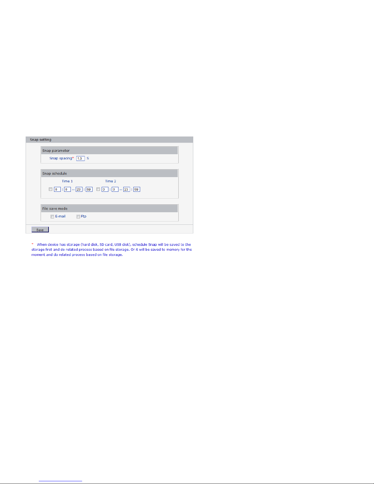
Below picture is the “snap schedule” page of INC-M20xx:
[Picture snapping parameters of the device]: set the interval of INC-M20xx picture snapping, minimum interval is 1 second.
[Snap Schedule]: set the period of scheduled snapping, any period of each day can be set up.
[Snapped files saving mode]: I NC-M20xx snapped pictures can be saved via E-mail sending or FTP uploading. E-Mail ser ver can be set up i n [Mail Setting s], FTP server can be set up in [FTP
Settings].
After setting all the pa rameters, click [save] to make the parameters val id.
5.8 COM Settings
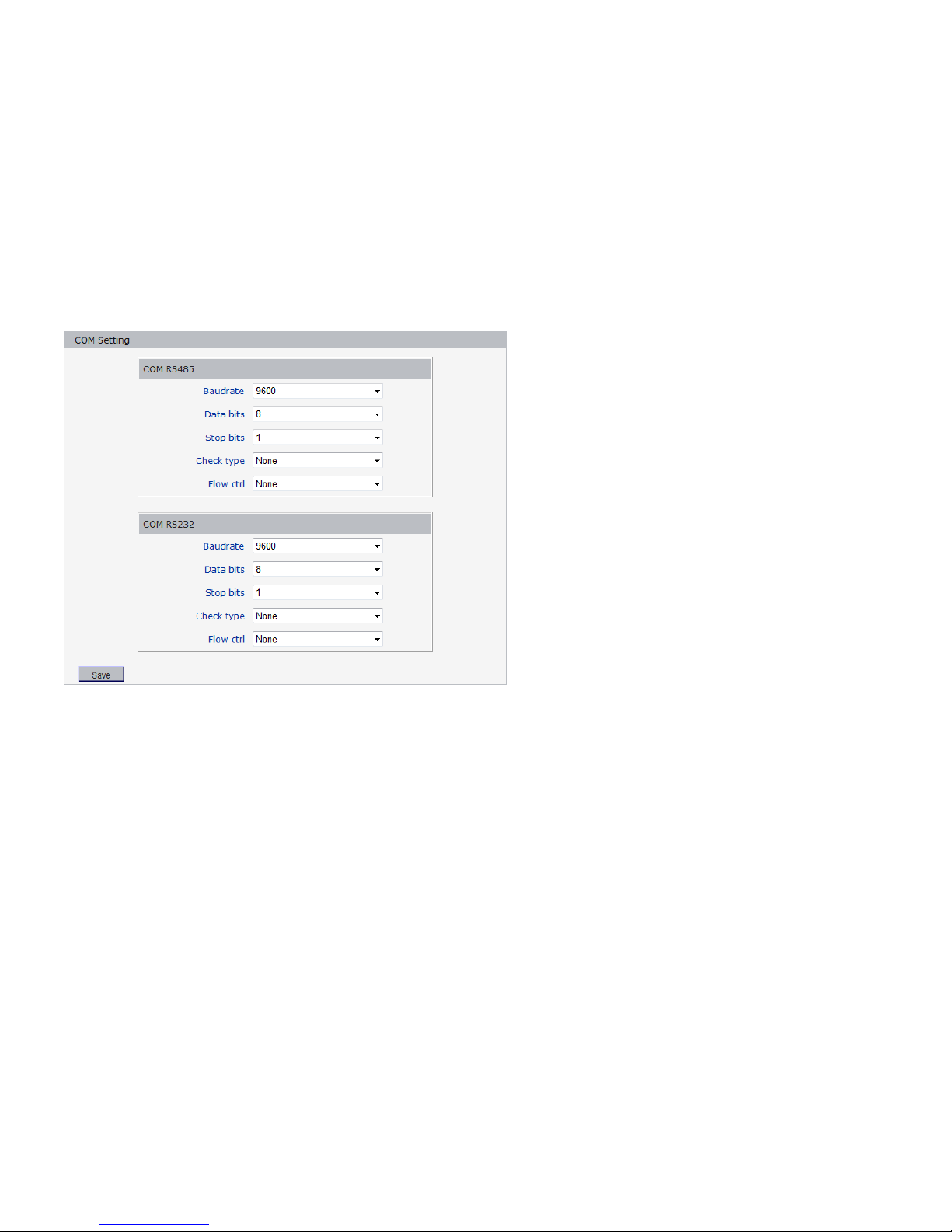
Below picture is the “Front-end setti ngs” page of INC- M20xx:
29
[Serial port settings]: When INC- M20xx is connected to RS485 (or RS232) commu nication or control device (e.g. PTZ decoder, dome camera), the parameters of RS485 (or RS232) need to set
according to the setti ngs of the communication control devi ce (address, protocol, baud rate), and the corresponding protocol n eed to be downloaded.
Note: Only when t he parameters and protocol are correctly set that the control of add-on comm unication control device can be im plemented.
[PTZ decoder protocol]
Decoder address: 1~255.
Built-in protocol: echo the built- in protocol nam e of current INC- M20xx.
PTZ decoder protocol files uploading: to upload the decoder/dome camera communication protocol selected by users. The system supports hundreds of decoder/dome camera communication protocol, it can
also be defined by users according to the standard format of protocol.
After setting all the parameters, click [save] to make the parameters valid.
5.9 Local Settings
30
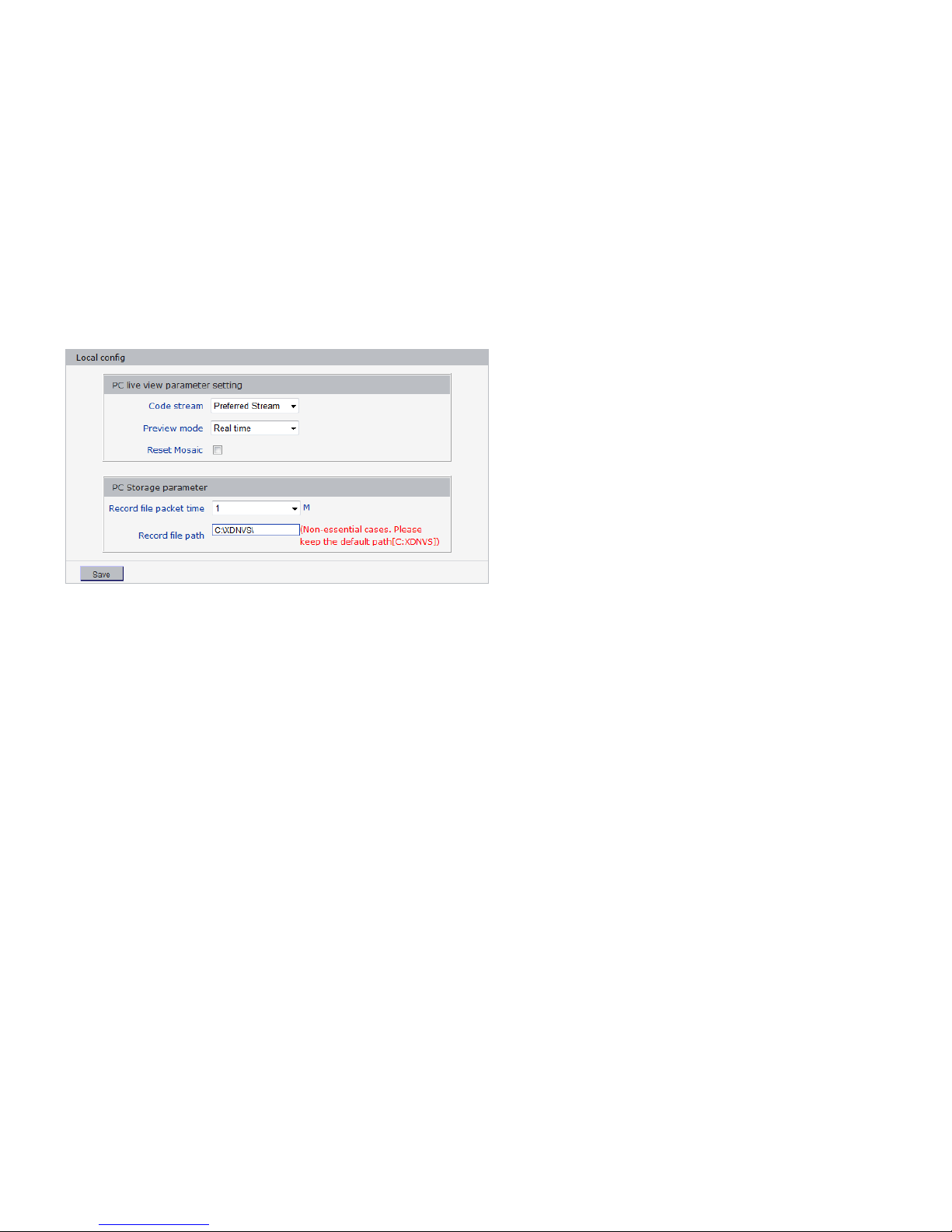
Below picture is the “Visit Settings” page of INC-M20xx:
[PC live view parameter setting]
Stream selection: set video stream for PC real-time preview, preferred stream and alternate stream are selectable. The parameters of preferred and alternate stream can be set up in [V ideo
Settings].
Preview mode: users can choose real- time priority or fluency priority mode according to their needs.
[Anti-crack]: select this option to make image quality better, but CPU usage rate will be higher at the same time.
[PC record storage settings]
Record files packing t ime: set packing time of record fil e for local PC when recording.
Record/snapped files storage directory: set the storage directory for local records and snapped fi les, the default path is C:\XDINC.
Appendix 1 Network Interface for INC-M20xx

-2-
The default network por ts of INC- M20xx a re:
TCP
80
Web port
5000
Communication port, audio/video data transmission port, talkback data
transmission port
UDP 5000
Audio/video data transmission port
Multi-cast port Multicast original port + channel number
Appendix 2 Default Network Parameters
Default network parameters
Note:
The wireless network IP address and cable network IP address cannot be in the same segment.
Appendix 3 Apply for DDNS domain name service
1 INC-M20xx DDNS Introduction
The DDNS function of INC-M 20xx
DDNS (Dynamic Domain Name Serv ice) refers to the real-time analysis of a fi xed domain name and the dy namic WAN IP address of the IP camera. With this function, all Internet users
Cable Network:
IP Address: 192.168.1.200 Data Port: 5000
Subnet mask: 255.255.255.0 Web Port: 80
Gateway: 192.168.1.1 DHCP: off
Wireless Network:
Network IP Address: 192.168.1.160 Frequency range: Auto
Gateway: 192.168.1.1 Mode: Auto
Subnet mask: 255.255.255.0

-3-
can visit the IP camera via a fixed domain name.
The DDNS process of INC-M20xx is as follow:
The DDNS process flow diagram of INC- M20xx
2 Apply for DDNS domain name service
Step 1: Sign up
Users need to sign up to manage and inquire a bout domain n ame status when using this dynami c domain name management system for the first time. V isit DDNS ser ver
(http://www.mvddns.net) to s ign up. See the picture below:

-4-

-5-
Step 2: User login
Enter registered user name and password, click “login” to enter into domain na me management interface as follow:
Step 3: Domain name registration
A domain name must be reg istered first, then put into use. Click “Domain name management ”, a page appears as follow:
Register and submit the domain name to be used. For example: “test.mvddns.net”.

-6-
Appendix 4 Visits INC-M20xx under different network environments
You can use your PC to connect INC-M 20xx through LAN or WAN, the following conte nts will tell yo u how to use INC- M20xx under different network environments.
1 LAN
Your network administrator assigns a LAN IP address to INC-M 20xx. The IP of your PC and INC-M20xx must be in the so me network segment to make visiting possible.
See below picture for the net work topology:
Please refer to below pic ture for the network settings:
Setup steps:
Step 1: Log in INC-M20xx via IE browser (the default IP is 192.168.1.200).
Step 2: Switch to the page [networ k settings], fill in the device IP address assigned by network administrator in to [Basic Parameters], e. g. 192.168.1. 200;
Step 3: Fill in subnet mask, default value is 255.255.255.0;
Step 4: Fill in gateway address, default value is 255.255.255.0;
Click [Save] to save the parameters. Starts the device, enter its IP address into IE browser to visit it.
2 Internet

-7-
You have three ways to connect your INC-M20xx to Internet:
Fixed IP mode;
Broadband and router sharing I nternet access mo de (dynamic obtainment of extranet IP address mode)
like ADSL and so on;
PPPoE dial-up access.
After INC-M20xx is connected to Internet, remote Internet users can visit INC -M20xx directly via domain name or IP address.
Fixed IP mode
See below picture for the net work topology:
Please refer to below picture for the network settings:
Setup steps:
Step 1: Log in INC-M20xx via crossover cable direct connection.(For details, please refer to [Hardware Installation])
Step 2: Switch to the page [networ k settings], fill in the device IP address requested from network service provider in to [Basic Parameters], e.g. 218.84.31.168;
Step 3: enter correct subnet mask, e.g. 255.255.255.192;
Step 4: enter correct gateway, e.g. 218.84.31.131;

-8-
After setup completes, click [Save] and restart the device, then connec t it to public network so that all Internet users can visit the I NC-M20xx remotely via entering
http://218.84.31.168 to IE bro wser.
Broadband and router sharing Internet access mode (dynamic obtainment of extranet IP address mode) like ADSL and so on;
For dia l-up access with router, see below pict ure for the network topology:
Users can set up DDNS domain name service at the same time. Fill the username and password which were applied in the D DNS server into the DD NS setting item, implement port
mapping from the router. The router judges and points to the INC-M20xx that need to be visited according to different ports, long-distance Internet users can visit the INC-M20xx on the
network via domai n name directly.
Please refer to below picture for the network settings:
DDNS setup steps:
Step 1: Log in DNNS server (e.g. http://www.mvddns.net), register user account and password: (for details, pl ease refer to Appendix 3)
Step 2: Click to open DDN S;
Step 3: Select DDNS service provider, e.g. mvddns.net;
Step 4: Fill in the registration name to log into DDNS server;

-9-
Step 5: Fill in the registration password to log into DDNS server;
Step 6: fill in the domain nam e applied on DDNS server, e.g. test.mvddns.net;
Step 7: Fi ll in DDNS server address, e.g.www.mvddns.net;
Step 8: fill in the port of DDNS server, default value is 30000 (users are recommended not to change it);
Step 9: fill in the por t number of public network data after mapping, the default port is 500 0.If several storage video servers are connected to one router, different data ports need to be
specified for each device, and port mapping needs to be done for every specified port.
Step 10: fill in the port number of public network web after mapping, the default port is 80.If several IP cameras are connected to one router, different web ports need to be specified for each
device, and port mapping needs to be done for every specified port.
After set up all the parameters, click [save] and restart to make the parameters valid.
PPPoE dial- up access
For INC-M20xx dial- up access, see below picture for the network topolo gy:
Setup steps:
Step 1: Log in INC-M20xx via crossover cable direct connection.(For details, please refer to [Hardware Installation])
Step 2: Set PPPoE parameters.(for details, please refer to [PPPOE settings])
Step 3: Connect INC- M20xx to Internet.
Step 4: If DDNS service is successfully set for the device, the device can be visited via entering domain name into IE browser.
See below picture for PPPoE settings:

-10-
Appendix 5 FAQ
1. Forget Password
Solution: There is a [RESET] button on the back panel of the INC-M20xx, press it to retrieve all default parameters (Factory Setting), user name and password are both “admin”.
Note: Please don’t press RESET if you are not a professional operator. After reset, all parameters will restore factory settings (except for the physical network address).
INC-M20xx audio/video function fai ls after abnormalities or abnormal power cut occur during upgrade, core edition is V4.0.0.0 (Backup file)
Solution: Connect the power cord and netwo rk cable of INC- M20xx, press on RESET button and release it after 10 seconds, system will run the back-up programm e automatically. After
enter into the back-up programme, upgrade system. The back-up programme offers only upgrade and parameter setup functions, audio and video functions are not available.
2. No video image displayed in IE browser
Possible reason: ActiveX not installed
Solution: ActiveX must be installed when visiting INC -M20xx for the first time via Internet Explore.
How to install: Visit INC-M20xx, clic k [Download Address], file download dialog wi ll pop up, select [Run] or [Save] to download. After download finishes, installation interface will pop
up, click “install”, the installation of ActiveX will start automatically, “Register OCX success” dialog box will pop up to remind the completio n of installation process .
3. Fail to visit INC- M20xx via IE after upgrade
Solution: Delete the caching of Browser.
Steps: Open IE—click “Tools”—select “Internet Optio ns”—clic k “delete files” button in “Internet temporary files”, select “delete all offline contents”, then click “OK” and re- log in
INC-M20xx.
4. The images do not flow
Possible reason 1: The frame rate of INC-M20xx is too low.

-11-
Solution: Improve the video frame rate
Possible reason 2: Too many users are viewing the image.
Solution: Block some clients or reduce the video frame rate.
Possible reason 3: The bandwidth is low.
Solution: Reduce video frame rate or video compression bit-rate.
5. Cannot visit INC-M20xx via IE browser
Possible Reason 1: Network is disconnected.
Solution: Connect your PC to network, chec king whether it works properly or not. Check whether there is cable failure or network failure caused by PC virus, until PCs can be connected
with the command of Ping.
Possible reason 2: IP Address has been occupied by other devices
Solution: Stop the connection between I NC-M20xx and Network, hook up INC- M20xx to the PC separately, and reinstall IP address according to the proper operations recommended.
Possible reason 3: IP addresses are in different subnets.
Solution: Check IP address, subnet masking address of the INC- M20xx a nd the settings of Gateway.
Possible reason 4: P hysical address of network conflict wi th INC-M 20xx
Solution: modify the physical address of INC- M20xx.
Possible Reason 5: Web port has been modified
Solution: Contact Network Administrator to obtain related information.
Possible Reason 6: Un known
Solution: Press RESET to retrieve default settings then connect it again, the default IP address is 192.168.55.1 60, subnet mask is 255.255.255.0
6. The color of images is abnormal (green or other colors)
Solution: Sometimes INC-M20xx images cannot display properly for the difference between Graphics Cards, the images ap pears to be green or other colors, then you should run the
programme Config.exe (or run C:\windows\system32\ Config.exe)to set the following parameters of d isplay buffer: auto- detection, used display card memory or system memory, then
reopen IE and connect INC-M 20xx.
7. There is no sound while monitoring
Possible Reason: No audio input connection
Solution: Check audio connection of the host
Possible Reason 2: the audio o ption of INC- M20xx is off
Solution: Ch eck audio parameter settings to see if you have opened t he audio.

-12-
8. Search INC software cannot find device
Possible reason: S earch INC software adopts multicast protocol to perform searching. But the firewall forbids multicast data packet.
Solution: disable the firewall.
9. Image processing doesn’t work properly
Possible Reason 1: system issue, DirectX function is disabled, which will cause slow display of images and abnormal color.
Possible Reason 2: hardware issue, graphics card doesn’t support image acceleration and hardware zooming functions.(For hardware issue, the only solution is to replace graphics card)
Solution: install DirectX image drive, then StartRuninput “DXDIAG” as follows:
Note:
Enable DirectDraw speedup, Direct3D speedu p, AGP veins speedup in DirectX function. If they can not be enabled, that means DirectX installation fails or hardware not supportive.
 Loading...