

Page 1

Rhein Tech Laboratories Client: IKUSI – Angel Iglesias
360 Herndon Parkway Model: T70M
Suite 1400 Standards: FCC 15.249/IC RSS-210
http://www.rheintech.com
Report #: 2007117
ID’s: PVT-T70MH3 & 4166A-T70MH3 Herndon, VA 20170
Appendix I: Manual
Please see the following pages.
Page 22 of 35
Page 2
70 - MINI
ENGLISH
70-MINI V.01.00 (01/07) 120009-0B.pdf IKUSI se reserva el derecho de modificar esta información sin previo aviso.
70-MINI V.01.00 (01/07) 120009-0B.pdf IKUSI reserves the right to modify this information without prior notification.
Page 3

70 MINI USER’S MANUAL
INDEX
Pág.
1.- SYSTEM DESCRIPTION: CHARACTERISTICS………………………………………………………..............1
2.- SAFETY INSTRUCTIONS…………………………………………………………….........................................4
2.1.- GENERALS………………………………………………………………………… ..........................................4
2.2.- HOISTING MACHINERY……………………………………………………………........................................ …4
2.3.- FCC RECOMMENDATIONS……………………………………………………………………………….............. 5
3.- INSTALLATION / SYSTEM ASSEMBLY………………………………………................................................5
3.1.- TRANSMITTER……………………………………………………….............................................…………....5
3.2.- RECEIVER…………………………………………………………………………......................................... ..6
3.3.- STARTING UP………………………………………………………………................................................... ..7
4.- TRANSMITTERS..........…............................................................................................................................8
4.1.- TYPE OF TRANSMITTERS……………………………………………………… ........................................... …8
4.2.- MAINTENANCE / TROUBLESHOOTING………………………………………… ............................................ …9
5.- RECEIVERS…………………………….......................................................................................................10
5.1.- TYPE OF RECEIVERS………………………………………………………………………………………….. .. 10
5.2.- MAINTENANCE / TROUBLESHOOTING…………………………………………………………………………... 11
6.- RADIO REMOTE SYSTEM FUNCTIONALITIES…...…………………………………………………............12
6.1.- GENERALS……..………………………………………………………………………………………............. 12
6.2.- BATTERY LEVEL INDICATION…..……………………………………………………………………………...... 12
6.3.- BASE CHANNEL CHANGING (T70MG10;T70MH3D;T70MH3;T70MH2 TRANSMITTER MODELS)...……... . ...13
6.4.- ID RELEASING (T70MG10;T70MH3D;T70MH3;T70MH2 TRANSMITTER MODELS)…………………........ ..15
6.5.- AUTO TEACHING MODE (T70MG10;T70MH3D;T70MH3;T70MH2 TRANSMITTER MODELS)………..…... ...15
6.6.- LOST TRANSMITTER SEARCHING MODE (T70MG10;T70MH3;T70MH2 TRANSMITTER MODELS)………... ...17
6.7.- PROGRAMMING PARAMETERS(T70MG10;T70MH3;T70MH2 TRANSMITTER MODELS)………..……..….. ...18
6.8.- PROGRAMATION (T70MH3D TRANSMITTER MODEL)……………….……………………..…………….…..... 20
6.8.1.- PROGRAMMING MODE BLOCK DIAGRAM…………….……………………………………………….... 21
6.8.2.- PROGRAMMABLE PARAMETERS…………………………………..……………………………....... ...23
6.8.3.- OUTPUT PROGRAMMING MODE (TELE ALIGNED)…………………….……………………………... ...24
70-MINI V.01.00 (01/07) 120009-0B.pdf IKUSI se reserva el derecho de modificar esta información sin previo aviso. i
70-MINI V.01.00 (01/07) 120009-0B.pdf IKUSI reserves the right to modify this information without prior notification.
Page 4

70 MINI USER’S MANUAL
1.- SYSTEM DESCRIPTION: CHARACTERISTICS
The systems are based on several handheld transmitter models (with the possibility of single step keypads
by function, known as generic transmitter, or double step keypads by function, known as hoisting transmitter) and
several receiver models, available with relays or static outputs –PWM outputs-.
The radio, integrated in the PCB of the transmitter and the receiver, is ready to work in different ISM bands,
according to different models.
The transmitter can be powered by alkaline batteries, type AA or rechargeable NiMH AA type batteries.
Applications are many and varied, depending on the emitter-receiver combination; basically the applications’
areas are as follows:
- Mobile applications (on board systems)
- Industrial hoisting applications (no EC)
- Other industrial hoisting applications (Chain hoists / Cat. 3 ;EN-954-1: EC)
- Other applications
SYSTEM CHARACTERISTICS
Transmitters: T70MG10-T70MH3-T70MG10D-T70MH3D Specifications
Available frequencies (ISM bands) 915MHz
RF Power (ERP) < 1mW 915MHz
Modulation type FSK 4800 bps and 7.200 bps
Protection IP65
Channel bandwidth 25KHz
Number of IDs 64K per band
Response time < 150ms
Working channel selection Automatic at transmitters’ start-up
Display option (for Remote Tele-Alignment) 2 lines x 12 characters / line + icons
Antenna Printed circuit board integrated (standard)
Weight 250gr
Dimensions Length = 160mm / Wide = 75mm / Height = 45mm
Rechargeable batteries Alkaline type AA 1,5V 2600mAh (-10ºC / +50ºC)
Battery life >12h (100% duty cycle) Alkalines 2500mAh
EEPROM Internal
Hoisting Safety Standards EN 954-1 Cat. 3 (hoisting models)
Active STOP (time) < 500ms (Cat.3 CE)
Passive STOP (time) < 2s (Cat.3 CE)
Operating temperature range -20ºC / +70ºC
Storage temperature range (24h) -25ºC / +75ºC
Storage temperature range –long periods- -25ºC / +55ºC
Signaling (transmitters without display) 1 bicoloured LED (RUN labeled)
Acoustic signaling Internal buzzer
T70MG10: Generic keypad transmitter (without display) 10 functions max. (1 step) + ON/OFF function
T70MH3: Hoisting keypad transmitter (without display) 6 functions max. (2 steps) + 2 AUX (1 step) + START
T70MG10D: Generic keypad transmitter (with display) 10 functions max. (1 step) + ON/OFF function
T70MH3D: Hoisting keypad transmitter (with display)
870MHz/433MHz
419MHz
< 5mW 870 MHz; <10 mW 433MHz
< 10mW 419MHz
Commercial Range
NiMH type AA 1,2V 1200mAh (-20ºC / +70ºC)
Industrial Range
>6h (100% duty cycle) NiMH 1200mAh
+ ON/STOP functions
6 functions max. (2 step) + START + ON/STOP
function
70-MINI V.01.00 (01/07) 120009-0B.pdf IKUSI se reserva el derecho de modificar esta información sin previo aviso. 1
70-MINI V.01.00 (01/07) 120009-0B.pdf IKUSI reserves the right to modify this information without prior notification.
Page 5

70 MINI USER’S MANUAL
R70MP10: Receiver with PWM outputs (10 outputs) Specifications
Available frequencies (ISM bands) 915MHz
Power supply 9-35V DC
Number of outputs 10 MOSFET (PWM)
Protection IP65
Antenna Printed circuit board integrated (standard)
Working channel selection Automatic at transmitters’ start-up
Weight 430 gr.
Dimensions Length = 151mm / Wide = 129mm (160mm with PG) /
EEPROM Internal
Status signaling MultiLED: 7 LED visible externally
Conexions Plug-In terminals: inputs/outputs with PG cable glands
Maximum current per output 5A
Maximum current output (total) 15A
PWM outputs frequency range 30 – 300Hz (5%+-95%)
Output accuracy 16 bits (power supply range)
Electrical input protection Fuse protected
Electrical output protections Polarity inversion / Shortcircuit
Operating temperature -20ºC / +70ºC
Storage temperature (24h) -25ºC / +75ºC
Storage temperature –long periods- -25ºC / +55ºC
Disconnecting security A MOSFET transistor connected with the positive value
870MHz/433MHz
419MHz
Height = 61mm
1) PG11 model power supply cable gland
2) PG16 model outputs cable gland
of the power supply provides security functions.
R70MR11: Receiver with relays outputs (11 outputs) Specifications
Available frequencies (ISM bands) 915MHz
870MHz/433MHz
419MHz
Power supply (depending on the model) 24/48V AC 50/60Hz (+20% / -30% Vin)
115/230V AC 50/60Hz (+20% / -30% Vin)
Number of outputs 11 RELAYS MODEL (No valid for CE hoisting
applications) 11 relays outputs.
Protection IP65
Antenna Printed circuit board integrated (standard).
Working channel selection Automatic at transmitters’ start-up
Weight 980 grs.
Dimensions Length = 205mm / Wide = 156mm / Height = 62mm
EEPROM Internal
Status signaling MultiLED: 7 LED visible externally
Conexions Plug-In terminals. Inputs/outputs with PG 21 (25 poles
maximum) cable gland.
Maximum current over resistive load 8A
Operating temperature range -20ºC / +70ºC
Storage temperature (24h) -25ºC / +75ºC
Storage temperature –long periods- -25ºC / +55ºC
70-MINI V.01.00 (01/07) 120009-0B.pdf IKUSI se reserva el derecho de modificar esta información sin previo aviso. 2
70-MINI V.01.00 (01/07) 120009-0B.pdf IKUSI reserves the right to modify this information without prior notification.
Page 6

70 MINI USER’S MANUAL
R70MR06: Receiver with output relays (6 outputs) Specifications
Available frequencies (ISM bands) 915MHz
870MHz/433MHz
419MHz
Power supply (depending on the model) 24V AC 50/60Hz (+20% / -30% Vin)
48V AC 50/60Hz (+20% / -30% Vin)
115V AC 50/60Hz (+20% / -30% Vin)
230V AC 50/60Hz (+20% / -30% Vin)
Number of outputs 06 RELAYS MODEL (CE hoisting applications / Cat.3
EN-954-1) 06 relays outputs (3 Hoist / 3 Travel)
Protection IP65
Antenna Printed circuit board integrated (standard).
Working channel selection Automatic at transmitters’ start-up
Weight 640 grs.
Dimensions Length = 151 mm / Wide = 129mm / Height = 61mm
EEPROM Internal
Status signaling MultiLED: 7 LED visible externally
Conexions Plug-In terminals: inputs/outputs with PG16 model
output cable gland.
Maximum current over resistive load 6A
Operating temperature range -20ºC / +70ºC
Storage temperature (24h) -25ºC / +75ºC
Storage temperature –long periods- -25ºC / +55ºC
70-MINI V.01.00 (01/07) 120009-0B.pdf IKUSI se reserva el derecho de modificar esta información sin previo aviso. 3
70-MINI V.01.00 (01/07) 120009-0B.pdf IKUSI reserves the right to modify this information without prior notification.
Page 7
70 MINI USER’S MANUAL
2.- SAFETY INSTRUCTIONS
2.1.- GENERALS
These instructions must be read carefully. This will allow you to install, use and maintain
this device in a proper state, reducing the risk of incorrect use.
Do not install the equipment in machines for the elevation of people or in explosive
atmospheres.
Any failure to comply with that set out in this manual will create a hazard, for which
reason the following must be respected:
¾ Ensure that the installation is carried out by trained, competent staff.
¾ The safety rules of the work area and of all competent authorities must be respected every
time.
¾ Ensure that this manual is permanently available to the operator and to the person in charge
of maintenance.
¾ Keep the transmitter out of the reach of unauthorised people.
¾ At the start of each day, check the correct working of the STOP button and the other safety
devices of the machine.
¾ In the event of any anomaly, use the STOP button.
¾ If there are several radio remote systems working in the same area, ensure that the used
transmitter corresponds to the machine that is being controlled. Identify the machine which
the transmitter corresponds to.
¾ Carry out regular checks and preventive maintenance.
¾ In the case of repairs, only use original spare parts.
¾ Never modify the device without prior study and approval of the manufacturer.
¾ Never use the device with a power supply other than the indicated.
¾ Never allow the device to be used by unqualified people.
¾ After being used, do not leave the transmitter in service without having pressed the STOP
button in order to prevent accidental operations.
¾ Do not use the device without visibility.
¾ Avoid knocking or dropping the set.
¾ Do not use the set if failure is detected.
2.2.- HOISTING MACHINES
¾ Ensure that the machine is fully halted throughout the estimated assembly time; clear the
work area and use safety clothing.
¾ In the case of overhead cranes, park the crane and position stop-ends (if these are not
available use appropriate signs) at a suitable distance in order to prevent collision with other
cranes in the same area.
¾ Verify the power supply and turn off the main contactor.
¾ Remember that the receiver has at least, more than one circuit under voltage.
¾ Even if the power supply is disconnected, there is still a risk of electrical discharges.
¾ Never forget to connect the ground cable.
¾ Use fireproof cables for the electrical connections.
¾ Check that the input power supply corresponds to the right voltage of the receiver.
¾ Be cautious: it may occur that the equipment has not been connected properly, which can
result in unforeseen movements during the start-up.
70-MINI V.01.00 (01/07) 120009-0B.pdf IKUSI se reserva el derecho de modificar esta información sin previo aviso. 4
70-MINI V.01.00 (01/07) 120009-0B.pdf IKUSI reserves the right to modify this information without prior notification.
Page 8
70 MINI USER’S MANUAL
p
2.3.- FCC RECOMMENDATIONS (only valid for equipment that works in 915MHz ISM band)
3.- INSTALATION / SYSTEM ASSEMBLY
3.1.-TRANSMITTER
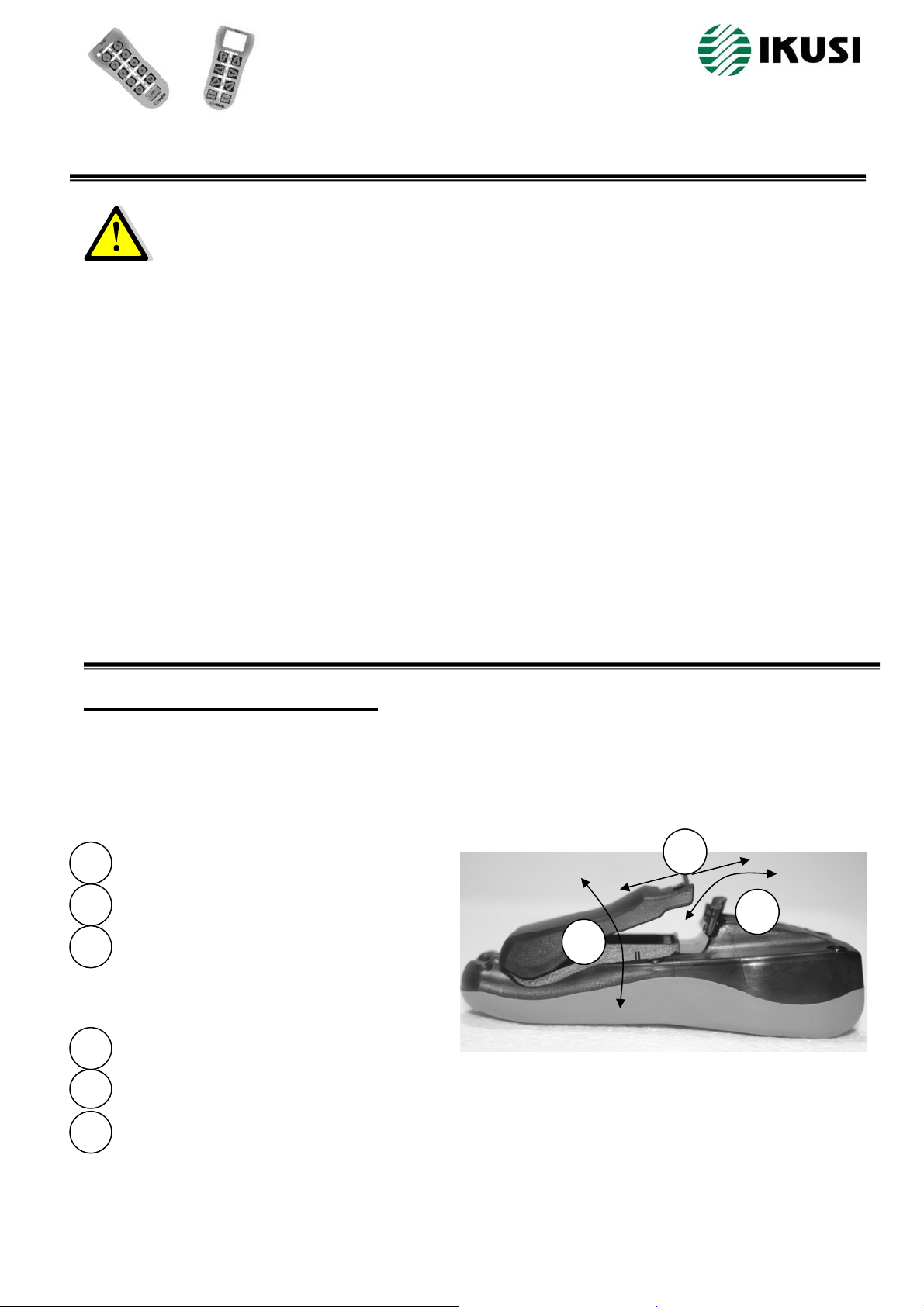
Proceed to open the transmitter’s battery compartment and introduce the supplied batteries into the battery
housing (2 AA type 1,5V alkaline batteries) respecting the +/- polarity, indicated inside the battery housing.
Procedure for o
“Open” the safety lock: rotate in the direction
1
indicated by the arrow.
“Open” lock tab: press in the direction
2
indicated by the arrow.
“Open” battery housing cover: rotate in the
3
direction indicated by the arrow.
Procedure for closing the mechanism of the
battery housing:
“Close” battery housing cover: rotate in the
3
direction indicated by the arrow.
“Close lock tab”: press in the direction
2
indicated by the arrow.
“Close the safety lock”: rotate in the
1
direction indicated by the arrow.
This device complies with Part 15 of the FCC Rules. Operation is subject to the following two
conditions:
1. this device may not cause harmful interference, and
2. this device must accept any interference received, including interference that may cause
undesired operation.
Changes or modifications not expressly approved by the manufacturer could void the user's
authority to operate the equipment.
To comply with FCC RF exposure compliance requirements, this device and its antenna must
not be co-located with, or operating in conjunction with, any other antenna or transmitter.
This equipment has been tested and found to comply with the limits for a Class A digital device,
pursuant to Part 15 of the FCC Rul.
These limits are designed to provide reasonable protection against harmful interference when
the equipment is operated in a commercial environment.
This equipment generates, uses, and can radiate radio frequency energy and, if not installed
and used in accordance with the instruction manual, may cause harmful interference to radio
communications.
Operation of this equipment in a residential area is likely to cause harmful interference in which
case the user will be required to correct the interference at his own expense.
ening the mechanism of the battery housing:
Abrir
Open
3
Abrir
Open
Cerrar
Close
Cerrar
Close
2
Cerrar
Close
Abrir
Open
1
70-MINI V.01.00 (01/07) 120009-0B.pdf IKUSI se reserva el derecho de modificar esta información sin previo aviso. 5
70-MINI V.01.00 (01/07) 120009-0B.pdf IKUSI reserves the right to modify this information without prior notification.
Page 9
70 MINI USER’S MANUAL
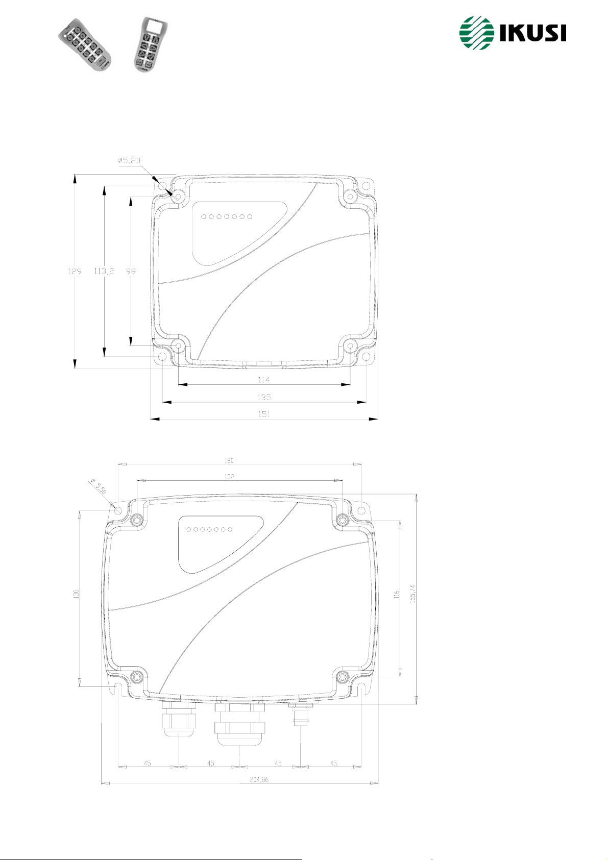
3.2.-RECEIVER
Find an easy access location for the receiver, free from obstacles, in order to facilitate the reception of the
transmitter’s radio signal, and far away from elements which can produce intense electric disturbance.
R70MP10 and R70MR06 models receiver dimensions:
R70MR11 model receiver dimensions:
70-MINI V.01.00 (01/07) 120009-0B.pdf IKUSI se reserva el derecho de modificar esta información sin previo aviso. 6
70-MINI V.01.00 (01/07) 120009-0B.pdf IKUSI reserves the right to modify this information without prior notification.
Page 10
70 MINI USER’S MANUAL
3.3.- STARTING UP.
TRANSMITTERS:
Turning on the T70MG10 transmitter model:
1- Insert the transmitter’s batteries (2 AA type batteries).
2- Press ON/OFF function. The transmitter remains powered.
3- Enter the key code: press simultaneously “7” + “8” functions.
4- Press “10” function. Equivalent to the START function.
5- Transmitter in ON state (solid green LED).
Turning on the T70MH3 / T70MH2 transmitter model:
1- Insert the transmitter’s batteries (2 AA type batteries).
2- Press ON/STOP function. The transmitter remains powered.
3- Enter the key code: press simultaneously ◄ ► functions.
4- Press START.
5- Transmitter in ON state (solid green LED).
Turning on the T70MH3D transmitter model:
1- Insert the transmitter’s batteries ( 2 AA type batteries).
2- Press ON/STOP function. LCD display message: “PLEASE WAIT”
3- Enter the key code: press simultaneously ◄ ► functions.
LCD display message: “PRESS START”
4- Press START.
5- Transmitter in ON state. LCD display message: “WORKING OK”
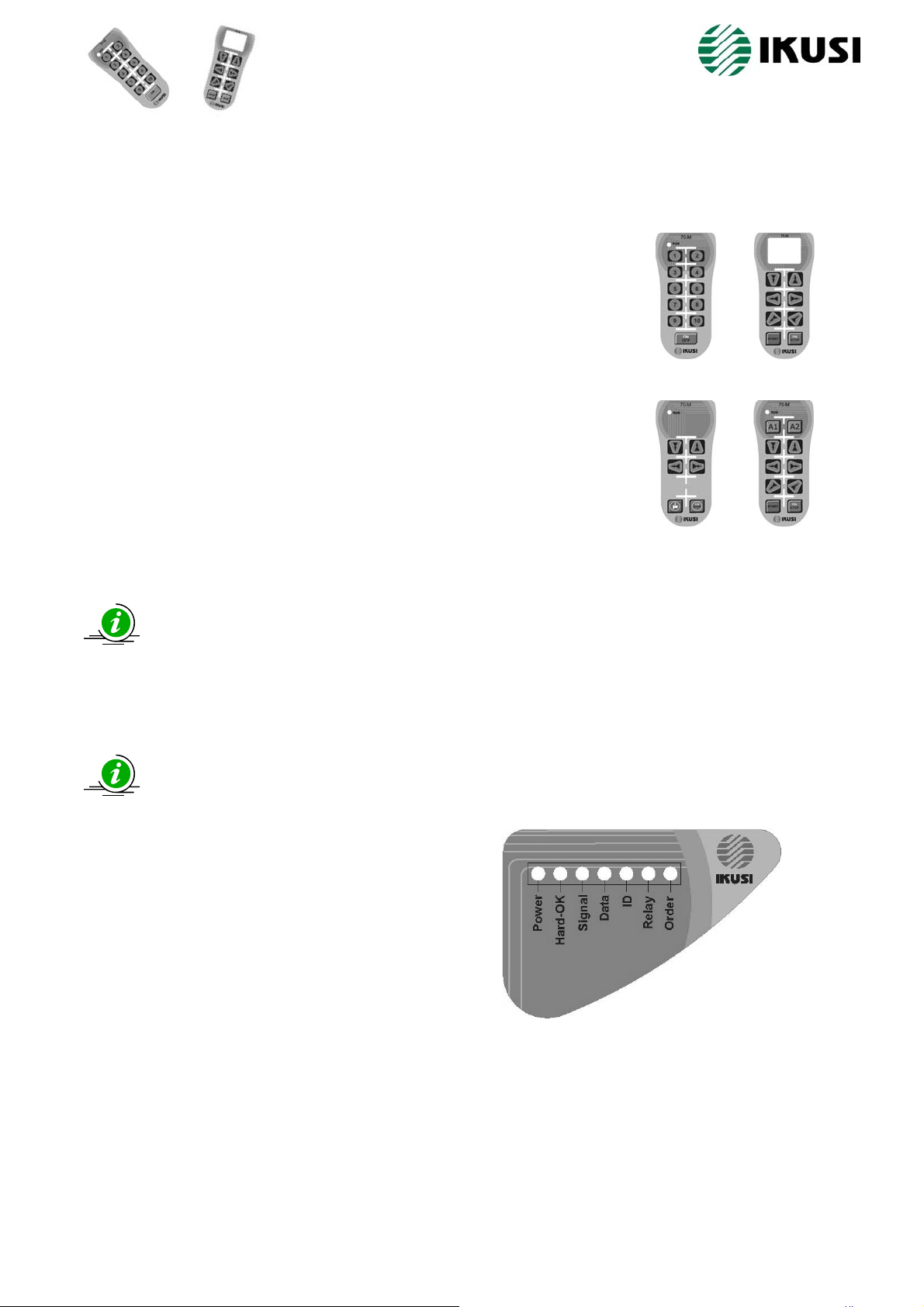
RECEIVERS
connection block diagram provide in this manual (page 11).
1) No radio link with the transmitter:
Transmitters without display: RUN signalling LED in solid green colour. In transmitters with
LCD display: “WORKING OK”; if the transmitter is the owner of the receiver.
Proceed to connect the power supply and the output connections. Use the plug-in terminals and the
LED’s signaling in correct operating mode:
“Power”: solid green.
“Hard-OK”: solid green.
“Signal”: Blinking if there are transmitters near and
in the same band.
2) There is a radio link with the transmitter:
“Power”: solid green.
“Hard-OK”: solid green.
“Signal”: green blinking fast.
“Data”: green blinking fast.
“ID”: green blinking fast.
3) With STOP relay activated and active outputs:
“Power”: solid green.
“Hard-OK”: solid green.
“Signal”: green blinking fast.
“Data”: green blinking fast.
“ID”: green blinking fast.
“Relay”: solid green if the STOP relay is activated.
“Order”: green (variable intensity), if one or more PWM outputs are activated.
“Order”: green (fixed intensity), if at least one or more relay outputs are activated.
T70MG10
T70MH2
T70MH3D
T70MH3
70-MINI V.01.00 (01/07) 120009-0B.pdf IKUSI se reserva el derecho de modificar esta información sin previo aviso. 7
70-MINI V.01.00 (01/07) 120009-0B.pdf IKUSI reserves the right to modify this information without prior notification.
Page 11

70 MINI USER’S MANUAL
play
4. – TRANSMITTERS
4.1. – Transmitters’ MODELS
T70MG10
Generic: máx. 10 functions
(1 step) + ON/OFF (without
display)
The models with LCD dis
Hoisting: máx. 6 functions
(2 steps) + 2 AUX: A1 and A2
(1 step) + START + ON/STOP
T70MH3 T70MH3D T70MH2
Hoisting: máx. 6 functions
(2 steps) + START +
ON/STOP (with display)
are alwaysrequired for Tele-Alignment purposes.
Hoisting (Cat. 3 EN-954-1): máx. 4
functions (2 steps) + START +
ON/STOP (without display)
70-MINI V.01.00 (01/07) 120009-0B.pdf IKUSI se reserva el derecho de modificar esta información sin previo aviso. 8
70-MINI V.01.00 (01/07) 120009-0B.pdf IKUSI reserves the right to modify this information without prior notification.
Page 12

70 MINI USER’S MANUAL
4.2.- MAINTENANCE / TROUBLE SHOOTING GUIDELINE
TRANSMITTER’S LED SIGNALLING
Status
Green flashing LED
LATENCY
SWITCHED ON:
TRANSMISSION
MODE (max. 1 min., it
only signalizes during
START action)
Without signal
Correct operating
mode
Activated
function
Switches to SWITCHED OFF
Without signal
mode
Red LED + buzzer Red LED + buzzer.
Low battery
Lost transmitter
ERROR
frame found
Red LED and buzzer
Without signal
continuously activated.
Red LED and buzzer
continuously activated. It
Without signal
maintains after releasing
START
TRANSMISSION
LOST Without signal Without signal
PASSWORD
AUTOID
LIBID
PROGRAMMING
PARAM
Green solid LED
Orange solid LED
Orange LED
Orange LED
Orange solid LED
Orange flashing LED
Without signal
Without signal
Without signal
Without signal
Without signal
Without signal
Red LED + buzzer: switches
to SWITCHED OFF mode
after 4 minutes.
Switches to SWITCHED OFF
mode
Switches to SWITCHED OFF
mode
Switches to SWITCHED OFF
mode
Switches to SWITCHED OFF
mode
Red LED + buzzer
Red LED + buzzer
Without signal
Buzzer bips during
1 minute
Without signal
Without signal
Without signal
Without signal
Without signal
Red LED and buzzer
continuously activated
Red LED and buzzer
continuously activated
Red LED and buzzer
continuously activated.
Red LED and buzzer
continuously activated.
Red LED and buzzer
continuously activated.
Red LED and buzzer
continuously activated.
Red LED and buzzer
continuously activated.
TELE-ALIGNMENT Without signal Without signal Without signal Without signal
Orange LED
SEARCHING MODE
70-MINI V.01.00 (01/07) 120009-0B.pdf IKUSI se reserva el derecho de modificar esta información sin previo aviso. 9
70-MINI V.01.00 (01/07) 120009-0B.pdf IKUSI reserves the right to modify this information without prior notification.
Without signal
Red LED + buzzer
Without signal
Buzzer continuously
activated
Red LED and buzzer
continuously activated.
Page 13

70 MINI USER’S MANUAL
5.- RECEIVERS
5.1.- TYPE OF RECEIVERS: CONNECTIONS BLOCK DIAGRAMS
R70MP10: PWM OUTPUT RECEIVER (10 OUTPUTS).
R70MR11: RECEIVER WITH OUTPUT RELAYS (11 OUTPUTS).
R70MR06: RECEIVER WITH OUTPUT RELAYS (6 OUTPUTS).
- Remember to connect the ground cable.
- Only use fireproof cables for connections.
- Select the appropriate voltage on the receiver, (230, 115 or 48 Vac). R70MR11 and R70MR06
models.
The voltage DC of the power supply (from 9v to 35v
DC, is conducted to the common wiring of the 10 output
switches (OUT1 until OUT10), through a SAFETY
switch which guarantees the output disconnection in
case of breakdown of some of the outputs. The
“RELAY” (STOP) switches between 2 fixed positions
NO (normally opened) and NC (normally closed). An
“LIB ID” function, with ID release pushbutton is
available on the electronic board, and it can be used in
case of transmitter’s breakdown. The ID release can be
also performed from the transmitter with a special
function.
RL-1: Power supply plug in terminals (24,48,115 and 230
V AC). Please note –see table- the right fuse values
depending on the input voltage.
RL-2: Plug in identified connection terminals, 1st and 2nd
speed, HOISTING; TROLLEY TRAVELLING; SAFETY;
START: STOP (Cat.3 EN-954)
LIB-ID: pushbutton to release the ID from the receiver.
EP70: On board plug in connector to connect an external
EP70 (External EEPROM).
RL-1: Power supply plug in terminals (24,48,115
and 230 V AC). Please note –see table- the right
fuse values depending on the input voltage.
RL-2: Plug in identified connection terminals, 1st
and 2nd speed (K1….K11) and START relay.
RL-3: Plug in terminal for connecting the STOP
relay (NO Cat.3 EN-954-1)
LIB-ID: pushbutton to release the ID from the
receiver.
EP70: On board plug in connector to connect an
external EP70 (External EEPROM).
70-MINI V.01.00 (01/07) 120009-0B.pdf IKUSI se reserva el derecho de modificar esta información sin previo aviso. 10
70-MINI V.01.00 (01/07) 120009-0B.pdf IKUSI reserves the right to modify this information without prior notification.
Page 14

70 MINI USER’S MANUAL
5.2.- MAINTENANCE / TROUBLE SHOOTING GUIDELINES
LED COLOUR STATUS REMARKS PROPOSED ACTION
POWER GREEN Switch On if powered Power supply OK Check the power supply
HARDOK GREEN
Blinking during start up process
RED
HARDOK
SIGNAL GREEN
DATA GREEN
ID
RELAY
ORDER
GREEN Blinking if a correct ID is received
GREEN STOP relay activated
GREEN
RECEIVER’S LED SIGNALING
Solid green LED if no error
detected
Solid red LED if one of these errors
appears:
- Watchdog activated /
Oscillator breakdown / wrong
ROM checksum
- Reset activated
- Blinking fast : wrong
EEPROM checksum / Data
corrupted.
LED Off if no radio signal detected
(Squelch)
LED Off if a wrong frame is received
Blinking if receiving good frames
Proportional lightning intensity
depending on the number of
activated outputs (PWM outputs); or
indicates that at least one output is
activated (RELAY outputs)
Receiver hardware OK OK
Please wait to finish the start up
process
Electronic board hardware
breakdown
Reprogramme EEPROM
- LED On and the transmitter
switched Off indicates
occupied radio channel
- LED On and DATA
switched Off indicates radio
channel occupied by a non
IKUSI system
LED Off and SIGNAL LED
On: Radio breakdown
Switched Off and DATA LED
switched On: no valid ID
SIGNAL; DATA and ID LED
On, indicates valid frames
from the transmitter. Correct
link.
Replace the electronic board
Verify transmitter’s radio and
battery
Replace radios
If the radio channel is not busy:
verify transmitter’s selected ID
or reset receiver ID
OK
70-MINI V.01.00 (01/07) 120009-0B.pdf IKUSI se reserva el derecho de modificar esta información sin previo aviso. 11
70-MINI V.01.00 (01/07) 120009-0B.pdf IKUSI reserves the right to modify this information without prior notification.
Page 15

70 MINI USER’S MANUAL
6.- RADIO REMOTE SYSTEM FUNCTIONALITIES
6.1.- GENERALS
6.2.- BATTERY LEVEL INDICATION
TRANSMITTER’S MODEL T70MH3D
Full battery: 3 black LED’s + frame. [▓ ▓ ▓]
Medium battery: 2 black LED’s + frame. [__▓ ▓]
Low battery: 1 black LED + frame. [___ ▓]
Empty battery: Blinking frame. [_____]
TRANSMITTER’S MODEL T70MH3 / T70MG10
Low battery state will be indicated with red LED blinking and intermittent buzzer’s sound (pulses of 0.1 sec. every
0.9 sec.: __/\_____________/\________).
The transmitter models without LCD display have restrictions with the access to the programation
parameters, due to the impossibility to show the Software Menu in Programation Mode.
The remote system receiver remembers the last ID used by the last current working transmitter.
This transmitter can be considered as the receiver’s owner. It means that if the receiver is going to
be used with another transmitter with a different ID, the receiver must released the current
transmitter’s ownership releasing the current ID code (LIB ID).This operation can be performed
from the current transmitter (performing LIB ID special function) or by pressing the LIB ID button
inside the receiver.
70-MINI V.01.00 (01/07) 120009-0B.pdf IKUSI se reserva el derecho de modificar esta información sin previo aviso. 12
70-MINI V.01.00 (01/07) 120009-0B.pdf IKUSI reserves the right to modify this information without prior notification.
Page 16

70 MINI USER’S MANUAL
g
1)
y
6.3.- BASE CHANNEL CHANGHING (TRANSMITTER MODELS:T70MG10;T70MH3D;T70MH3;T70MH2)
T70MG10 TRANSMITTER MODEL
With the transmitter switched off, press “ON/OFF”. Transmitter in stand-by or LOW CONSUMPTION mode.
2) Entering base channel changing mode:
3) The current base channel information is displayed: Number of red pulses = Number of units of the
channel; Number of green pulses = Number in units of ten of the channel.
4) Once the orange LED lights continuously, proceed to change the base channel
Note: Press “4” function to leave the process without updating the new base channel.
The transmitter switches to stand-b
5) To validate the new base channel, press “10” function.
The new updated base channel value will show with red and green
LED pulses:
Number of red pulses = Number of units of the channel.
Number of
6) Updating and sending the new base channel data to the receiver (orange LED blinking).
7) Once the new base channel is recorded in the receiver the transmitter switches to OFF mode (Orange LED
stops blinking ).
+
Press function “1”, as many times as the number of units of ten of the new base channel.
Note: To programme channels from 1 to 9, do not press this function –equivalent to 0 value--
Press function “2”, as many times as the number of units of the new base channel.
reen pulses = Number in units of ten of the channel.
BASE CHANNEL CHANGING MODE (Press “5” and “10” functions
simultaneously) -> Wait until the orange LED lights continuously.
or LOW CONSUMPTION mode.
70-MINI V.01.00 (01/07) 120009-0B.pdf IKUSI se reserva el derecho de modificar esta información sin previo aviso. 13
70-MINI V.01.00 (01/07) 120009-0B.pdf IKUSI reserves the right to modify this information without prior notification.
Page 17

70 MINI USER’S MANUAL
)
)
2)
T70MH3D / T70MH3/ T70MH2 TRANSMITTER MODELS
1) With the transmitter switched off, press “ON/OFF”. Transmitter in stand-by or LOW CONSUMPTION mode.
Entering in the base channel changing mode:
3) The current base channel information is displayed:
“Freq Change”
“Channel NN” -> (01,02,03……….MAXCAN) NN = 01,02,03,…………, MAXCAN
MAXCAN = 11 in 870 MHz
MAXCAN = 69 in 433MHz and 915MHz
Use “UP”and ”DOWN” functions to change the base channel:
4
To validate the new channel press “START”
5
The new channel information will be displayed in the LCD:
“Freq Change”
“Channel __” -> (01,02,03……MAXCAN) NN = 01,02,03,…………, MAXCAN
MAXCAN = 11 in 870 MHz
MAXCAN = 69 in 433MHz and 915MHz
Note1: To leave without updating the change, press “ESC” in
Note2: To leave without updating the change, press “RIGHT” in T70MH2 model.
6) Updating and sending the new base channel data to the receiver.(the message blinks in the LCD display).
7) Once the new base channel is recorded in the receiver the transmitter switches to OFF mode. (LCD
switched off).
Note: In two steps pushbutton keypads the special functions are activated pressing the first
step.
+
With “DOWN” function, choose the units of the new channel.
Nota: 0 to programme channels from 1 to 9.
With “UP”, function choose the number of units of ten of the new channel.
BASE CHANNEL CHANGING MODE (Press “RIGHT” and “START” functions
simultaneously) -> Message in the LCD display: “FREQ CHANGE”
70-MINI V.01.00 (01/07) 120009-0B.pdf IKUSI se reserva el derecho de modificar esta información sin previo aviso. 14
70-MINI V.01.00 (01/07) 120009-0B.pdf IKUSI reserves the right to modify this information without prior notification.
Page 18

70 MINI USER’S MANUAL
)
2)
g
y
6.4 ID RELEASING (LIB ID) (TRANSMITTER MODELS:T70MG10;T70MH3D;T70MH3;T70MH2)
T70MG10 TRANSMITTER MODEL
DURING THE ID RELEASING PROCESS THE ORANGE LED BLINKS AND THE BUZZER IS ACTIVE. ID RELEASED PROCESS
FINISHED: LED OFF and BUZZER OFF.
T70MH3D / T70MH3 / T70MH2
DURING THE ID RELEASING PROCESS THE ORANGE LED BLINKS AND THE BUZZER IS ACTIVE. ID RELEASED PROCESS
FINISHED: LED OFF and BUZZER OFF.
6.5 AUTO TEACHING MODE (AUTO ID) (TRANSMITTER MODELS:T70MG10;T70MH3D;T70MH3;T70MH2)
T70MG10 TRANSMITTER MODEL
The orange LED switches on-off when every password value is pressed.
At the validation process the orange LED blinks, indicating that the new values are being recorded into the receiver.
Once the operation has finished the orange LED switches off and the transmitter switches to stand-by or LOW CONSUMPTION mode.
It allows releasing the receiver’s ownership of the working transmitter.
1
With the transmitter switched off, press “ON/OFF”. Transmitter in stand-by or LOW CONSUMPTION mode.
To enter in LIB ID mode, press simultaneously “4” and “10” functions.
+
It allows releasing the receiver’s ownership of the current working transmitter.
1) With the transmitter switched off, press “ON/STOP”.
2) To enter in LIB ID mode, press simultaneously “UP” and “START” functions.
Note: In two steps pushbutton keypads the special functions are activated pressing the first
step.
It allows to re
1) With the transmitter switched off, press “ON/OFF”. Transmitter in stand-by or LOW CONSUMPTION mode.
2) To enter in AUTO ID mode, press “9” and “10” buttons simultaneousl
3) Introduce the “default password” : “8-8-8-8-8” -> “10” to validate.
PASSWORD (DEFAULT)
-
+
ister in the receiver’s database a new transmitter’s ID (maximum = 32 ID)
+
Keep pressed until the orange LED lights continuously.
► ► ►
>
VALIDATE
70-MINI V.01.00 (01/07) 120009-0B.pdf IKUSI se reserva el derecho de modificar esta información sin previo aviso. 15
70-MINI V.01.00 (01/07) 120009-0B.pdf IKUSI reserves the right to modify this information without prior notification.
Page 19

70 MINI USER’S MANUAL
)
y
)
)
T70MH3 / T70MH2 TRANSMITTER MODEL
T70MH3D TRANSMITTER MODEL
It allows to register in the receiver’s database a new transmitter’s ID (maximum = 32 ID)
1) With the transmitter switched off, press “ON/STOP”.
Transmitter in stand-by or LOW CONSUMPTION mode.
2
To enter in AUTO ID mode, press “DOWN” and “START” buttons simultaneousl
+
3) Introduce the “default password” : “ENTER-ENTER-ENTER-ENTER” -> “START” to validate.
PASSWORD (DEFAULT)
The orange LED switches on-off when every password value is pressed.
At the validation process the orange LED blinks, indicating that the new values are being recorded into the receiver.
Once the operation has finished the orange LED switches off and the transmitter switches to stand-by or
LOW CONSUMPTION mode.
Note: In two steps pushbutton keypads the special functions are activated pressing the first
step.
It allows to register in the receiver’s database a new transmitter’s ID (maximum = 32 ID)
1
With the transmitter switched off, press “ON/STOP”. Transmitter in stand-by or LOW CONSUMPTION mode.
2) To enter in AUTO ID mode, press “DOWN” and “START” buttons simultaneously; keep pressed this buttons
until the message
+
Introduce the “default password” : “ENTER-ENTER-ENTER-ENTER” -> “START” to validate.
3
PASSWORD (DEFAULT)
Note: In two steps pushbutton keypads the special functions are activated pressing the first
step.
Keep pressed until the orange LED lights continuously.
► ► ►
is shown in the LCD display.
****
► ► ►
>
>
VALIDATE
VALIDATE
70-MINI V.01.00 (01/07) 120009-0B.pdf IKUSI se reserva el derecho de modificar esta información sin previo aviso. 16
70-MINI V.01.00 (01/07) 120009-0B.pdf IKUSI reserves the right to modify this information without prior notification.
Page 20

70 MINI USER’S MANUAL
O
2)
4)
2)
)
)
)
)
1)
y
g
6.6 LOST TRANSMITTER SEARCHING MODE (TRANSMITTER MODELS: T70MG10;T70MH3;T70MH2)
T70MG10 TRANSMITTER MODEL
T70MH3 TRANSMITTER MODEL
T70MH2 TRANSMITTER MODEL
It allows finding one or more lost transmitters in the same working area.
1) With the transmitter switched off, press “ON/OFF”. Transmitter is stand-by or LOW CONSUMPTION mode.
To enter in SEARCH mode, press simultaneously “7” and “10” functions.
+
3) Entering “3”-“1”-“3” function’s sequence, the SEARCH function will execute.
► ►
Pressing “10” function the transmitter switches to stand-by or LOW CONSUMPTION mode.
STAND BY or LOW CONSUMPTION MODE
It allows findin
With the transmitter switched off, press ON/STOP to switch on (stand-b
2) To enter in SEARCH mode, press simultaneously “ENTER” and “START” functions.
3
Entering “ENTER-DOWN-ENTER” function’s sequence, the SEARCH function will execute.
4
Pressing “START” the transmitter switches to stand-by or LOW CONSUMPTION mode.
Note: In two steps pushbutton keypads the special functions are activated pressing the first
step.
It allows finding one or more lost transmitters in the same working area.
1) With the transmitter switched off, press “ON/STOP”. Transmitter in stand-by or LOW CONSUMPTION mode.
To enter in SEARCH mode, press simultaneously “ENTER” and “START” functions.
+
3
Entering “ENTER-DOWN-ENTER” function’s sequence, the SEARCH function will execute.
► ►
4
Pressing “START” the transmitter switches to stand-by or LOW CONSUMPTION mode.
SWITCHED OFF or LOW CONSUMPTION MODE
Note: In two steps pushbutton keypads the special functions are activated pressing the first
step.
Keep pressed until the orange LED lights continuously.
SEARCH FUNCTION EXECUTING
RANGE LED BLINKS PERMANENTLY
one or more lost transmitters in the same working area.
+
► ►
STAND-BY or LOW CONSUMPTION MODE
Keep pressed until the orange LED lights continuously.
EXECUTE SEARCH
Keep pressed until, the orange LED will light
EXECUTE SEARCH
state).
70-MINI V.01.00 (01/07) 120009-0B.pdf IKUSI se reserva el derecho de modificar esta información sin previo aviso. 17
70-MINI V.01.00 (01/07) 120009-0B.pdf IKUSI reserves the right to modify this information without prior notification.
Page 21

70 MINI USER’S MANUAL
1)
g
6.7 PROGRAMMING PARAMETERS (PARAM) (TRANSMITTER MODELS: T70MG10;T70MH3;T70MH2 )
1) When executing DOWNLOAD/UPLOAD LOCAL, if the EEPROM is wrong or not connected,
the red LED will indicate “EEPROM Error” (red LED blinking during 5 secs. aprox.) and the
transmitter switches to PARAM mode, ready to select a new sequence (DOWNLOAD
LOCAL or UPLOAD LOCAL or DOWNLOAD REM).
2) In case of “Grave Error”, the red LED and the buzzer becomes active continuously.
3) The beginning of the EEPROM updating process is signalized with orange LED, blinking in
different ways.
4) The right ending of the EEPROM updating process is signalized with green LED
continuously lightning on during 5 secs. aprox. and the transmitter switches to stand-by or
LOW CONSUMPTION mode.
DOWNLOAD LOCAL
UPLOAD LOCAL
DOWNLOAD REMOTE
It allows making EEPROM backup copies between: internal EEPROM and external EP70 EEPROM; between
EP70 external EEPROM and internal EEPROM; and to recover the content of the receiver’s internal EEPROM
into the transmitter’s internal EEPROM.
1) DOWNLOAD LOCAL: It allows discharging the content of an internal EEPROM into an external EP70
extractable EEPROM.
2) UPLOAD LOCAL: It allows discharging the content of an extractable EP70 EEPROM into the internal
EEPROM.
3) DOWNLOAD REM: It allows discharging the content of a receiver’s internal EEPROM into the
transmitter’s internal EEPROM.
4) SWITCHED OFF: With this option the transmitter switches to a low consumption mode.
T70MG10 TRANSMITTER MODEL
Transmitters:
If during transmitter’s start up, an external EP70 is connected, the content of this EP70 is automatically
stored into the internal EEPROM. Remark: This operation disables the internal EEPROM check
between the transmitter and the receiver contents.
Receivers:
If an external EP70 is connected to the receiver’s logic board and the LIB ID pushbutton is pressed during
at least 2 seconds, the content of the EP70 is stored into the internal EEPROM.
With the transmitter switched off, press “ON/OFF”. Transmitter in stand-by or LOW CONSUMPTION mode.
2) To enter in PARAM mode, press simultaneously “4” and “10” functions.
Keep pressed until, the orange LED lights continuously.
►
►
► ►
DOWNLOAD LOCAL
►
STAND-BY or LOW CONSUMPTION MODE
UPLOAD LOCAL
►
DOWNLOAD REM
3) Enterin
+
modes:
►
►
►
► ►
70-MINI V.01.00 (01/07) 120009-0B.pdf IKUSI se reserva el derecho de modificar esta información sin previo aviso. 18
70-MINI V.01.00 (01/07) 120009-0B.pdf IKUSI reserves the right to modify this information without prior notification.
Page 22

70 MINI USER’S MANUAL
1)
2)
)
g
1)
2)
)
g
T70MH3 TRANSMITTER MODEL
T70MH2 TRANSMITTER MODEL
With the transmitter switched off, press “ON/STOP”. Transmitter in stand-by or LOW CONSUMPTION mode.
To enter in PARAM mode, press simultaneously “ENTER” and “START” functions.
+
3
Enterin
modes:
► ►
►
Note: In two steps pushbutton keypads the special functions are activated pressing the first
step.
With the transmitter switched off, press “ON/STOP”. Transmitter in stand-by or LOW CONSUMPTION mode.
To enter in PARAM mode, press simultaneously “ENTER” and “START” functions.
+
3
Enterin
modes:
►
►
►
Note: In two steps pushbutton keypads the special functions are activated pressing the first
step.
Keep pressed until the orange LED lights continuously.
► ►
DOWNLOAD LOCAL
►
UPLOAD LOCAL
►► ► ►
►
Keep pressed until the orange LED lights continuously.
►
►
►
►
STAND-BY or LOW CONSUMPTION MODE
DOWNLOAD LOCAL
►
UPLOAD LOCAL
► ►►
STAND-BY or LOW CONSUMPTION MODE.
DOWNLOAD REM
DOWNLOAD REM
70-MINI V.01.00 (01/07) 120009-0B.pdf IKUSI se reserva el derecho de modificar esta información sin previo aviso. 19
70-MINI V.01.00 (01/07) 120009-0B.pdf IKUSI reserves the right to modify this information without prior notification.
Page 23

70 MINI USER’S MANUAL
6.8 PROGRAMATION (TRANSMITTER MODEL T70MH3D)
The availability to enter in programation mode is restricted to transmitter’s models with LCD (model T70MH3D).
The software architecture presents this following message’s levels:
1
M E S S A G E
1 . X1
M E S S A G E
1 . X1 . X2
M E S S A G E
1 . X1 . X2 . X3
M E S S A G E
TRANSMITTER’S SWITCH ON PROCESS
With the transmitter switched off, press “ON/STOP” during 2 secs. and the following message is displayed in the LCD:
I N I T I A L I Z I N G
P L E A S E W A I T
This message will remain in the LCD display when reading the internal EEPROM. Finally the transmitter will
switch off remaining in switched off mode, (no message will be displayed); only the battery level icon will be
displayed:
[▓ ▓ ▓] / [__▓ ▓] / [___ ▓] / [_____] (different battery level indications: full, medium, low and empty).
SEQUENCE TO ACCESS TO PROGRAMATION MODE
With the transmitter switched off, press “ENTER” and “SART” simultaneously, during 3 secs. The message “PROGRAMATION”
will be displayed in the LCD.
Programation mode sequence activation from switched off mode.
P R O G R A M A T I O N
Pressing ESC, the transmitters turns to switched off mode.
Pressing ENTER, the software menu is available (use “UP” / “DOWN” arrows to navigate in the software):
+
UP
DOWN
VALIDATE (ENTER) and ACCESS TO A LOWER LEVEL OF THE MENU
LEAVE / ACCESS TO AN UPPER LEVEL OF THE MENU
70-MINI V.01.00 (01/07) 120009-0B.pdf IKUSI se reserva el derecho de modificar esta información sin previo aviso. 20
70-MINI V.01.00 (01/07) 120009-0B.pdf IKUSI reserves the right to modify this information without prior notification.
Page 24

70 MINI USER’S MANUAL
6.8.1- PROGRAMMING MODE: BLOCK DIAGRAM
1.0
DOWNLOAD LOC
1
PARAMETERS
1.1
UPLOAD LOC
1.2
DOWNLOAD REM
PROGRAMATION
2.0
ADJUST
2
TELETEACH
WAIT PLEASE
3
SEARCH
SERCHING
LOST EMITTER
2.1
RESET VALUES
CONFIRM
RESET
70-MINI V.01.00 (01/07) 120009-0B.pdf IKUSI se reserva el derecho de modificar esta información sin previo aviso. 21
70-MINI V.01.00 (01/07) 120009-0B.pdf IKUSI reserves the right to modify this information without prior notification.
Page 25

70 MINI USER’S MANUAL
2.0.0
PASSWD ID
PASSWD ID
XXXX
2.0.1
SEARCHMODE
SERACH MODE
ON / OFF
2.0
ADJUST
2.0.2
TOUT LATENCY
TOUT LATENCY
MIN N
2.0.3
TOUT OFF
TOUT OFF
MIN NN
2.0.4
T STOP
T STOP
SEG NN .N
(*) The START relay activation can be programmed as
MOMENTARY or LATCHING, as well, while pressing
START function.
2.0.5
TELEALIGN
SELECT OUT 1….10
SELECT OUT START
(*)
2.0.5.START
OUT MODE
(*)
OUT MODE
LATCH / TEMP
70-MINI V.01.00 (01/07) 120009-0B.pdf IKUSI se reserva el derecho de modificar esta información sin previo aviso. 22
70-MINI V.01.00 (01/07) 120009-0B.pdf IKUSI reserves the right to modify this information without prior notification.
Page 26

70 MINI USER’S MANUAL
6.8.2.- PROGRAMMABLE PARAMETERS (TELE-ALIGNED):
PROGRAMMABLE VALUES (TELE-ALIGNED)
Parameter Default value Range (programmable values)
PASSWD ID xxxx Any combination of 4 functions, excluding 2
START (Coded) Described in the Service Manual
SEARCH MODE OFF ON, OFF. (SEARCH MODE)
TOUT LATENCY 4min 1 to 6min; steps of 1 min, and infinite (“INF” value) minutes. (Time to LATENCY state).
TOUT OFF 15min 10 to 20min step of 1 min, and infinite (“INF” value). (Time from LATENCY state to SWITCH OFF state).
TSTOP 2sec 1 to 10sec.: steps of 0,1sec. (Passive STOP time)
OUTMODE MOMENTARY MOMENTARY or LATCHING (OUTPUTS: OPERATING MODES)
SOFTSTART ON ON or OFF (Enable or Disable soft start)
SOFTSTOP ON ON or OFF (Enable or Disable soft stop)
0,0sec, 0,1sec, 0,2sec, 0,3sec, 0,4sec, 0,5sec, 0,6sec, 0,8sec, 1,0sec, 1,2sec, 1,5sec, 1,7sec, 2.0sec, 2,5sec 3,5sec, 5.0sec (Ramp
ACCELRAMP 0,1sec
DECELRAMP 0,1sec
ASSIGN TABLE Xxx Described in the Service Manual
PWM FREQ 300Hz 30Hz to 300Hz ; Step = 10Hz. (R70MP10: PWM output frequency adjustment. Independent for each output).
acceleration adjustment for each output)
0,0sec, 0,1sec, 0,2sec, 0,3sec, 0,4sec, 0,5sec, 0,6sec, 0,8sec, 1,0sec, 1,2sec, 1,5sec, 1,7sec, 2.0sec, 2,5sec 3,5sec, 5.0sec (Ramp
deceleration adjustment for each output)
nd
speed, STOP and START (Coded)
70-MINI V.01.00 (01/07) 120009-0B.pdf IKUSI se reserva el derecho de modificar esta información sin previo aviso. 23
70-MINI V.01.00 (01/07) 120009-0B.pdf IKUSI reserves the right to modify this information without prior notification.
Page 27

70 MINI USER’S MANUAL
)
)
)2)
6.8.3.- OUTPUT PROGRAMMING MODES (TELE-ALIGNED)
In Menu 2.0.5.x.0 OUTMODE: select “MOMENTARY” for MOMENTARY OUTPUT and “LATCHING” FOR
LATCHED (LOCKED) OUTPUT.
OUTPUT PROGRAMMING WITH ONE STEP KEYPAD: “MOMENTARY” OUTPUT MODE or “LATCHING”
OUTPUT MODE.
1) RAMP-UP PROGRAMMING (RAMP= ON
V
= 100%
MAX
V
= XX %
MAX
M
= ON ▲
I
(Press Order)
M
= OFF ▼(Depressed order)
I
MI =
ON/OFF PROGRAMMING(RAMP= OFF)
V
= 100%
MAX
In 2.0.5.x.1 software menu SOFT START, select:
ON to enable ACCELERATION RAMP
OFF to disable ACCELERATION RAMP
In 2.0.5.x.2 software menu SOFT STOP, select:
ON to enable DEACCELERATION RAMP
ON ▲ M
I =
OFF to disable DEACCELERATION RAMP
OFF ▼
In MOMENTARY mode, the outputs remain actives while the orders are pressed. They can be
programmed in ramp mode (soft start and soft stop programmable independently) or ON/OFF
mode.
= Whatever 10 functions or generic keypad orders ( 1, 2, 3……….8, 9 10)
M
I
V
V
MAX
= 100%
MAX
= 100%
T
1
RAMP = ON
T
2
RAMP = OFF
OUTPUT PROGRAMMING WITH ONE STEP KEYPAD: “LATCHING” OUTPUT MODE.
1) RAMP-UP PROGRAMMING (RAMP= ON
V
MAX
= XX %
V
MAX
= 100%
2) ON/OFF PROGRAMMING (RAMP= OFF
V
= 100%
MAX
ME = ON
(Press one order)
ME = ON / ON / OFF
(Press again the active order or press ON /OFF
ME = ON
(Press one order)
ME = ON / ME = ON / OFF
(Press again the active order or press ON /
OFF)
In LATCHING output mode the outputs remain active, once the order has been pressed until: a) the
same order is pressed again; b) the ON/OFF function is pressed. They can be programmed in ramp
mode (soft start and soft stop programmable independently) or ON/OFF mode.
= Whatever 10 functions or generic keypad orders ( 1, 2, 3……….8, 9 10)
M
I
70-MINI V.01.00 (01/07) 120009-0B.pdf IKUSI se reserva el derecho de modificar esta información sin previo aviso. 24
70-MINI V.01.00 (01/07) 120009-0B.pdf IKUSI reserves the right to modify this information without prior notification.
Page 28

70 MINI USER’S MANUAL
)
)
▲
▲
▼
▼
p
p
)
)
▼
T = 0
▲
T
T
The ramp up time (up or down) is fully programmable (Tele-Aligned). The programmed time is the
time to achieve Vmax. from 0v of the PWM output signal.
TWO STEP KEYPAD PROGRAMMING
RAMP-UP PROGRAMMING (RAMP= ON
1
1 VEL/SPEED = ON
V OUT = XX %
▲
1 VEL/SPEED = ON
V OUT = 0
V
= PROGRAMMABLE VALUE BY EEPROM (XX % ) / T
OUT
For two steps keypads, the 2nd speed value is V max (100%).
The 1st s
2
ON/OFF PROGRAMMING(RAMP= OFF
For two steps keypads, the 2nd speed value is V max (100%).
The 1st s
1 VEL/SPEED = ON
V OUT = 0
V
= 100%
MAX
= 5s
max
= 0s
min
2 VEL/SPEED = ON
V OUT = XX %
T = 0
eed value is Vout, and is programmable (Tele-aligned = XX %).
1 VEL/SPEED = ON
V OUT = XX %
2 VEL/SPEED = ON
V
V OUT = XX %
= PROGRAMMABLE VALUE BY EEPROM (XX % ) / T
OUT
eed value is Vout, and is programmable (Tele-aligned = XX %).
T
= 5s
max
= 0s
T
min
▼
2 VEL/SPEED = ON
V OUT = V max = 100%
▲
2 VEL/SPEED = ON
V OUT = 100%
▲
In 2.0.5.x.3.0 software menu ACCEL RAMP, select:
ACCEL TIME
SEG NN
In 2.0.5.x.3.1 software menu DECEL RAMP, select:
DECEL TIME
SEG NN
In 2.0.5.x.1 software menu SOFT START,
select:
ON to enable ACCELERATION RAMP.
▼
1 VEL/SPEED = ON
V OUT= XX %
2 VEL/SPEED = OFF
V OUT = XX %
= PROGRAMMABLE TIME
I
▼
2 VEL/SPEED = OFF
V OUT = XX %
= PROGRAMMABLE TIME
I
1 VEL/SPEED = ON
V OUT = XX %
OFF to disable ACCELERATION RAMP.
In 2.0.5.x.2 software menu SOFT STOP,
select:
ON to enable DEACCELERATION RAMP.
OFF to disable DEACCELERATION
RAMP.
1 VEL/SPEED = OFF
V OUT = 0
1 VEL/SPEED = OFF
V OUT = 0
70-MINI V.01.00 (01/07) 120009-0B.pdf IKUSI se reserva el derecho de modificar esta información sin previo aviso. 25
70-MINI V.01.00 (01/07) 120009-0B.pdf IKUSI reserves the right to modify this information without prior notification.
Page 29

HEADQUARTER - SPAIN
IKUSI - Ángel Iglesias S.A.
Pº Miramón, 170
20009 San Sebastián
SPAIN
Tel.: +34 943 44 88 00
Fax: +34 943 44 88 20
ikusi@ikusi.com
www.ikusi.com
AUSTRALIA - NEW ZEALAND
IKUSI ANZ PTY LTD
Tel.: +61 3 9720 7022
Fax: +61 3 9720 7422
ika@ikusi.com
CHILE
INGENIERÍA IKUSI CHILE, LTDA.
Tel.: +56 2 335 9661
Fax: +56 2 233 7511
ikc@ikusi.com
FRANCE
IKUSI FRANCE SARL
Tel.: +33 1 43 03 52 22
Fax: +33 1 43 03 52 42
ikf@ikusi.com
MEXICO
IKUSI-GS MÉXICO, S.A. DE C.V.
Tel.: +52 55 5663 8600
Fax: +52 55 5663 8684
contacto@ikusi-gs.com.mx
PERU
ÁNGEL IGLESIAS, S.A. SUC. DEL PERÚ
Tel.: +51 1 211 6500
Fax: +51 1 442 2073
ikpe@ikusi.com
PORTUGAL
IKUSI ELECTRÓNICA, LDA.
Tel.: +351 22 947 8240
Fax: +351 22 947 8249
ikp@ikusi.com
RUSSIA
IKUSI RUSSIA, LLC.
Tel.: +7 495 583 93 41
Fax: +7 495 586 17 71
ikr@ikusi.com
UNITED ARAB EMIRATES
IKUSI MIDDLE EAST FZE
Tel.: +971 4 204 5606
Fax: +971 4 204 5610
ikme@ikusi.com
70-MINI V.01.00 (01/07) 120009-0B.pdf IKUSI se reserva el derecho de modificar esta información sin previo aviso.
70-MINI V.01.00 (01/07) 120009-0B.pdf IKUSI reserves the right to modify this information without prior notification.
Page 30

70-MINI V.01.00 (01/07) 120009-0B.pdf IKUSI se reserva el derecho de modificar esta información sin previo aviso.
70-MINI V.01.00 (01/07) 120009-0B.pdf IKUSI reserves the right to modify this information without prior notification.
Page 31

70-MINI V.01.00 (01/07) 120009-0B.pdf IKUSI se reserva el derecho de modificar esta información sin previo aviso.
70-MINI V.01.00 (01/07) 120009-0B.pdf IKUSI reserves the right to modify this information without prior notification.
Page 32

70-MINI V.01.00 (01/07) 120009-0B.pdf IKUSI se reserva el derecho de modificar esta información sin previo aviso.
70-MINI V.01.00 (01/07) 120009-0B.pdf IKUSI reserves the right to modify this information without prior notification.
Page 33

70-MINI V.01.00 (01/07) 120009-0B.pdf IKUSI se reserva el derecho de modificar esta información sin previo aviso.
70-MINI V.01.00 (01/07) 120009-0B.pdf IKUSI reserves the right to modify this information without prior notification.
 Loading...