

1
ECM
(Eight Channel Monitor)
Description
An integral part of the IKON AVS fault monitoring network, the ECM, is designed
to monitor up to eight separate loudspeaker lines using a combination of
methods to cater for virtually all possible contingencies.
The ECM is inserted between the amplifier and loudspeaker circuit. Using a
combination of voltage comparison and current monitoring techniques the system
can be configured for use with low impedance and 100V line systems.

2
Contents
DESCRIPTION 1
CONTENTS 2
ECM INTRODUCTION 3
M ONITORING GUIDE 3
FUNCTIONALITY 4
F
RONT PANEL CONTROLS SEE APPENDIX
A 4
RS232 SEE APPENDIX B 4
REAR PANEL CONNECTIONS 5
Amplifier and Speaker connections See Appendix C 5
Event input See Appendix D 5
Common Fault See Appendix E 5
Power Supply See Appendix E 5
Fibre Connectors See Appendix F 5
CALIBRATION AND SETUP 6
APPENDIX A 7
ECM CALIBRATION 7
APPENDIX B 8
RS232 CONNECTING DETAILS 8
APPENDIX C 9
SPEAKER CONNECTIONS 9
High impedance speaker monitoring 9
ECM wiring 9
FAULT DETECTION 11
LINE LEVELS 11
LOW IMPEDANCE SPEAKER MONITORING 11
DETECTION WIRING 11
FAULT DETECTION 12
AUDIO CONNECTIONS 4 WIRE SYSTEM . 13
A
UDIO CONNECTIONS 2 WIRE SYSTEM
. 13
APPENDIX D 14
EVENT I NPUT DESCRIPTION 14
Configuration 14
Connections 16
APPENDIX E 17
COMMON FAULT RELAY 17
P
OWER SUPPLY
17
DC POWER INLET 17
APPENDIX F 18
O PTICAL FIBRE CONNECTORS 18

3
ECM Introduction
Monitoring guide
The ECM is suitable for use on 100V line systems from 30w to 1Kw ( or from 5w
if using an EOL terminator ) as well as low impedance systems ranging in power
from 60w to1Kw into 4 or 8 Ohms. Calibration is simple with the unit auto ranging
to select the correct settings. The acceptance window for fault reporting is also
automatically set with an option for the user to configure the system using the
windows based software.
The system is configured to detect the presence of a low level 20KHz signal
when no audio program is present. This signal is then used to process an
accurate test of the load and line. When an audio program is detected, the
monitoring process continues but with an increased window of acceptance to
allow for variations in audio program material. The system will revert to 20KHz
monitoring either at the end or during a break in audio program material.
The 20KHz signal needs to be introduced to the system either directly
through a DSP sound engine or separately via an external oscillator.
A windows based software utility is available for use with the unit allowing simple
system configuration and adjustments. The software allows unit identification,
selection of monitoring type, configuration of the event input and common fault
output as well as monitoring of mains & DC supplies.
4
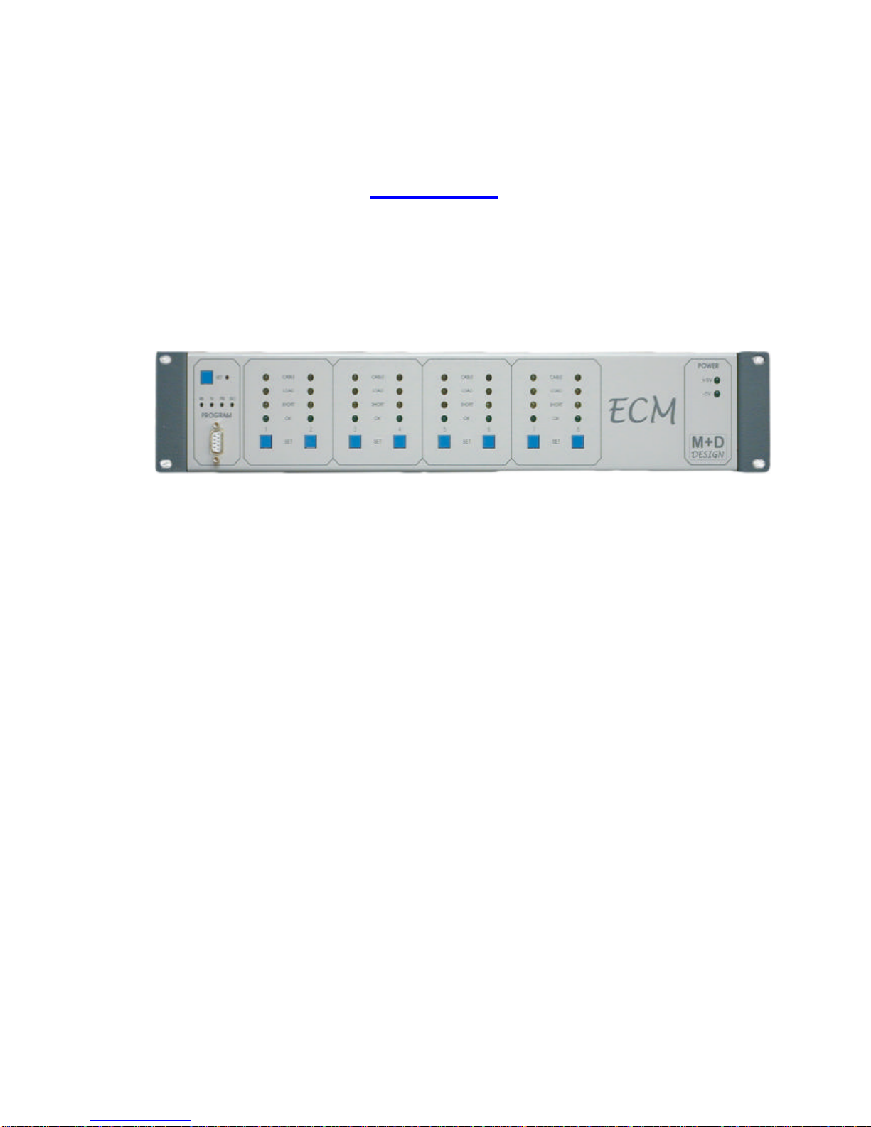
Functionality
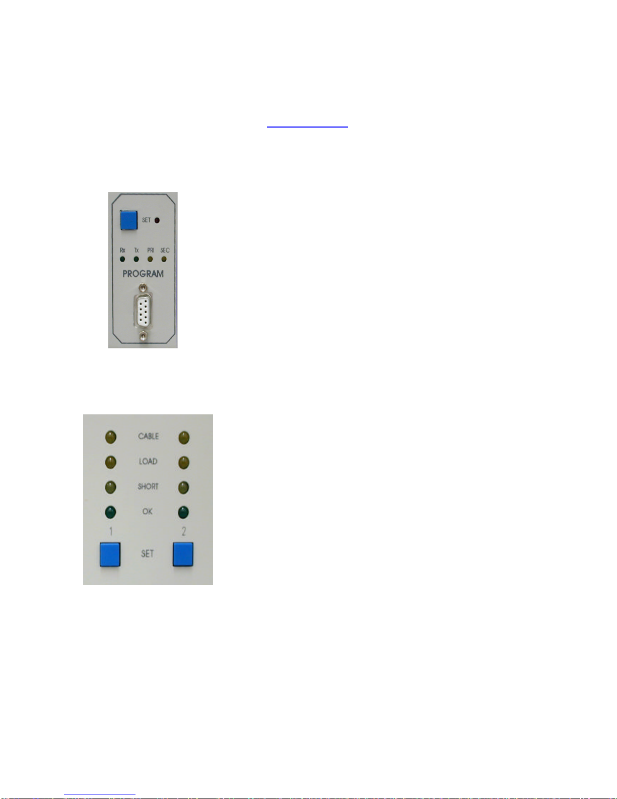
Front Panel Controls See Appendix A
Front panel controls allow calibration of the unit and LED’s display the current
status of each individual circuit.
♦
Each channel when calibrated will show its current status by the illuminated
LED.
• Loudspeaker Cable, Load or Short Fault
• Loudspeaker Circuit OK
♦Power LED’s indicate the unit power rails are operating when illuminated.
♦ Fibre transmit and receive LED’s illuminate when data is present on either
primary or secondary fibres.
♦The red LED illuminates when the set button is pressed for calibration.
RS232 See Appendix B
♦Program the system via the RS232 port using the software utility.
5
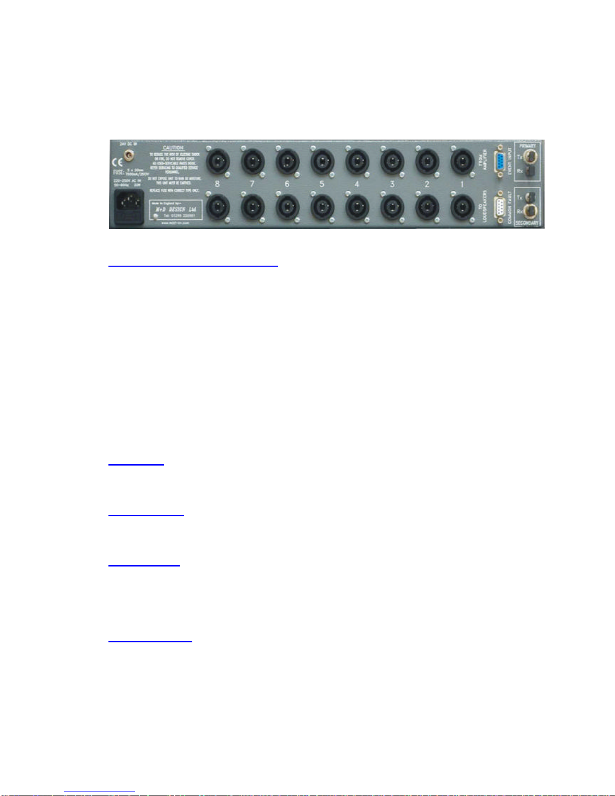
Rear Panel Connections
Amplifier and Speaker connections See Appendix C
♦ Eight individual input/output speakon connectors are located on the rear
panel.
♦ Connections from the amplifier output are connected to terminals marked 1+
and 1- respectively.
♦ Connections to loudspeaker circuits monitoring low impedance only connect
1+ and 1-.
For small 100V line circuits ( max of 8 speakers ) 1+ and 1- are used as the
signal send and 2+ used for a third wire ‘End of Line’ return.
For larger 100V line circuits, or where complete rings are used, the ‘End of Line’
return is connected to 2+ and 2-.
Event input See Appendix D
Four opto-isolated inputs for connection to external sources. Typically used to
monitor DSP processor or UPS status.
Common Fault See Appendix E
A change over relay provides a common fault output that can be configured to
provide a change in status for any fault.
Power Supply See Appendix E
A 230V 50Hz mains supply socket. The mains fuse ( T500mA 20mm) is mounted
within this socket. The fuse carrier also contains a spare fuse.
A 24V DC battery backup input is also provided. The software utility allows
status monitoring of both power supplies.
Fibre Connectors See Appendix F
Twin ( primary & secondary ) ST fibre connectors for incoming and outgoing fibre
connections to other hardware in the system. The software utility allows either
single or dual fibre operation with states of system verified and reported.

6
Calibration and Setup
♦ Press the Set button ( top left ). Red led will illuminate.
♦ Select all channels on unit to be calibrated using buttons 1 to 8.
♦ Play audio source at Max SPL approx. Audio must be present for a period of
one minute ( minimum ).
♦ Press the set button ( top left ). Red led will now flash on and off.
♦ Then stop audio.
♦ Introduce 20KHz at low level and observe the yellow LED’s above channel
number.
• LOAD If illuminated 20KHz to High
• SHORT If illuminated 20KHz to Low
•
OK Illuminated to show channel selected
The OK LED and the Short LED should be illuminated to show the 20KHz signal
to LOW.
Increase the 20KHz level until the Short LED goes out.
When only the OK led is lit on channels 1 to 8 press the SET button again and
calibration is complete.
The OK LED should remain lit.
To test a circuit simply remove 20KHz signal and observe LED’s on that channel.
A LOAD fault should be shown illuminated.
Return the 20KHz signal and the OK LED should be shown illuminated.
7
Appendix A
ECM Calibration
The set button is used to calibrate the loudspeaker circuits.
♦ Press once and release ( Red LED will illuminate )
To calibrate channel N.
♦ Press the button below channel N.
♦ Play the audio source at max SPL for 1 minute.
♦ Press the Set button once ( Red LED and LED’s below
will flash alternately).
♦ Stop the audio.
♦ Introduce the 20KHz at low level.
♦ Observe the two LED’s above the OK LED.
Short indicates that the 20KHz to low
Load indicates that the 20KHz to high
Adjust the 20KHz until both LED’s are off.
♦ Once this is achieved press the set button
to complete the calibration.
♦ The OK LED should now be illuminated.
♦ Test the circuit simply by removing the 20KHz signal.
♦ A load fault will be indicated after a short period.
♦ Return the 20KHz signal.
♦ The fault LED should be replaced by the OK LED.

8
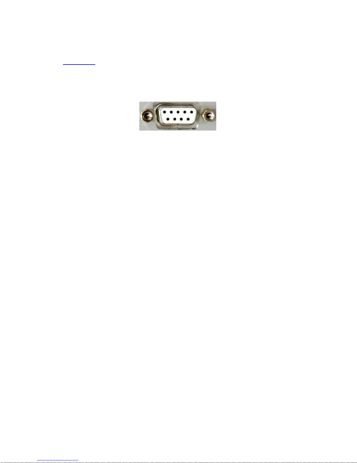
Appendix B
RS232 Connecting Details
This is located on the front panel and provides a bi-directional RS232 port used
to communicate with an IBM compatible PC.
Pin 1 No connection
Pin 2 Serial data receive (RX)
Pin 3 Serial data transmit (TX)
Pin 4 No connection
Pin 5 Ground
Pin 6 No connection
Pin 7 No connection
Pin 8 No connection
Pin 9 No connection
9
Appendix C
Speaker Connections
High impedance speaker monitoring
This is intended to monitor voltage driven multi-speaker lines, such as 100V
systems. High impedance monitoring operates by measuring signal levels at the
amplifier and the far end of the speaker line. Whilst three and four wire
monitoring is preferable, it is also possible to use the two wire monitoring method
recommended for low impendence circuits.
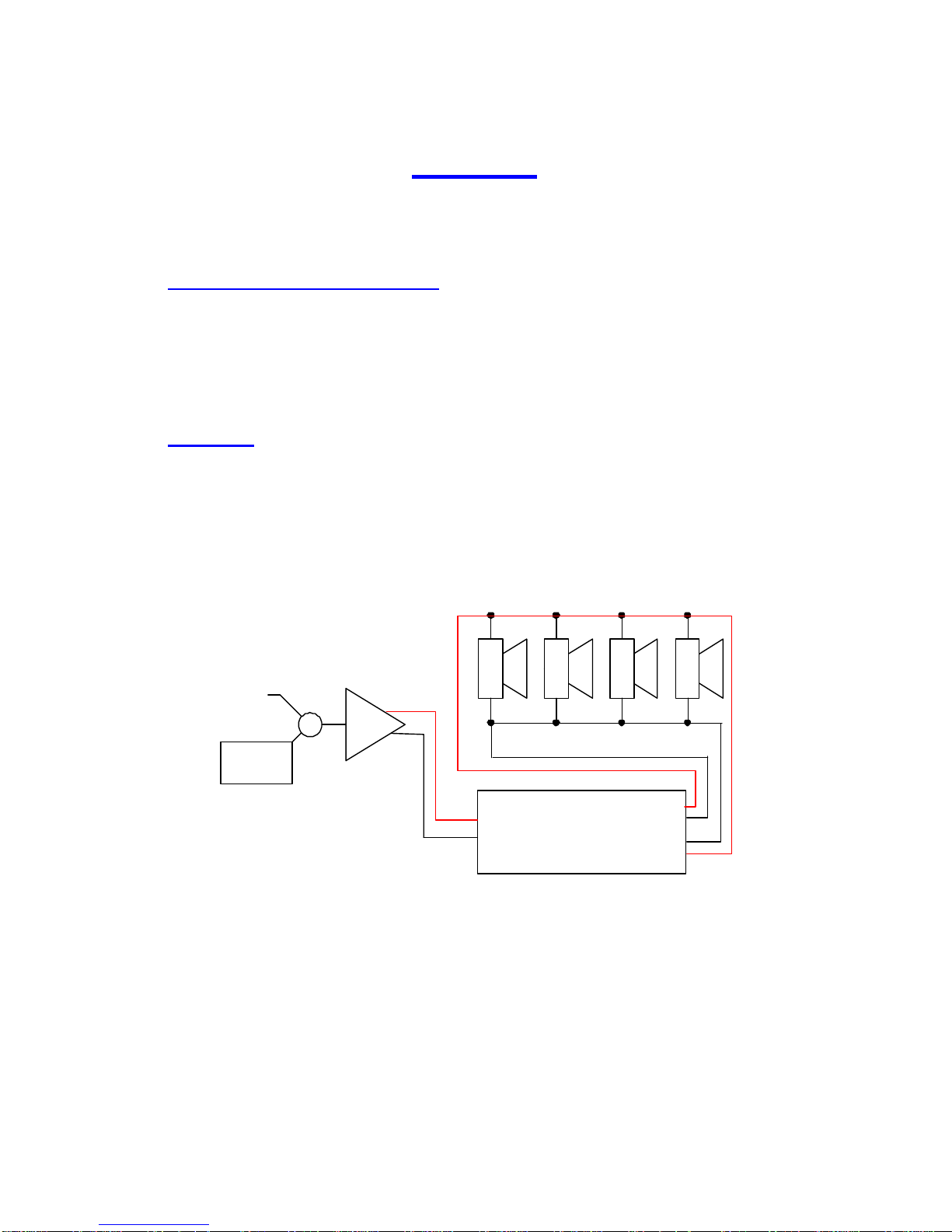
ECM wiring
This detection requires a pair of connections taken directly from the power
amplifier and a second pair from the far end of the speaker line.
20kHz
oscillator
+
Audio
signal
ECM
Channel N
From
Amp
Amplifier
1+
1-
To
Speakers
1+
1-
2+
2-
Mixer
10
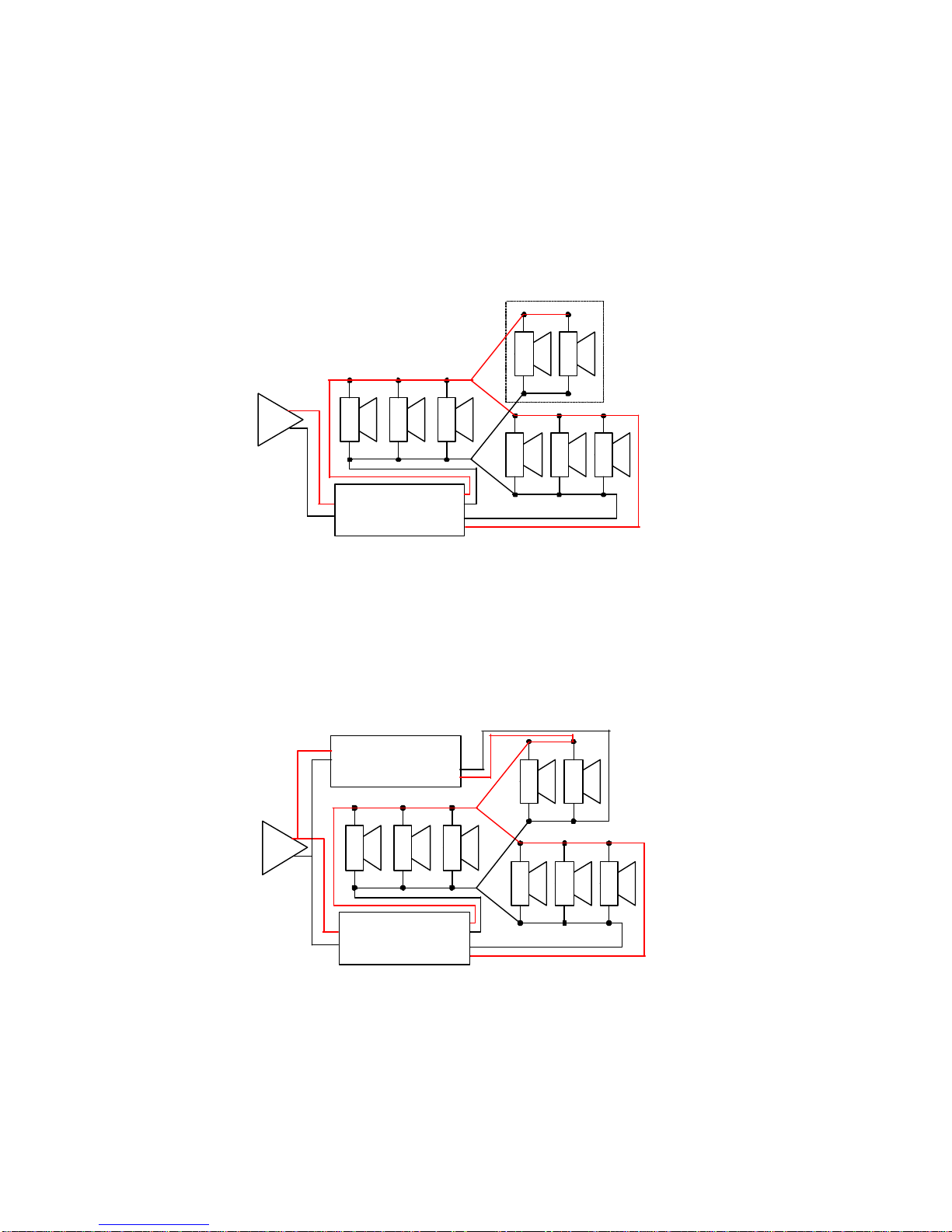
It is essential that the speaker lines contain no spurs, as these will not be
monitored, as shown below.
The solution below is not recommended. Impedance changes on either
section of speakers will result in two faults on the system. Difficult to resolve and
pinpoint where fault has occurred.
The most effective solution to spurs is to rewire as a separate circuit.
This section un-monitored
From
Amp
To
Speakers
Amplifier
1+
1-
ECM
Channel N
1+
1-
2+
2-
Amplifier
1+
1-
From
Amp
To
Speakers
ECM
Channel 1
1+
1-
2+
2-
From
Amp
To
Speakers
ECM
Channel 2
1+
1-
2+
2-
1+
1-
11
Fault detection
The speaker line is monitored for : -
1. Cable fault, a break in the speaker cable. This is detected by
signal presence at the power amplifier and not at the far end of the
speaker line.
2. Load fault, an excessive change in speaker line loading. This is
detected when the speakers line attenuation changes by more than
20 percent. Attenuation here is power amp level divided by far end
of speaker line level.
3. Short fault, a short on the speaker line or a failed power amplifier.
This is detected by the absence of signal at the power amplifier.
Line levels
The unit can monitor signal levels from 20dBU to 100V line.
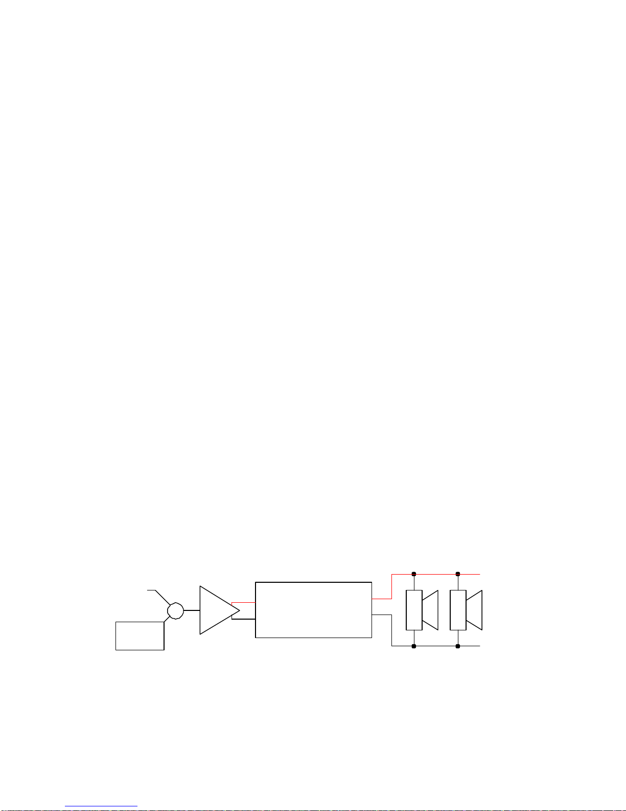
Low impedance speaker monitoring
This is intended to monitor an amplifier driving a single or small group of
speakers. Low impedance monitoring measures the signal voltage and current
from the output of the amplifier.
Detection wiring
Low impedance monitoring requires the amplifier output to be routed through the
ECM unit, as shown bel ow.
20kHz
oscillator
Audio
signal
From
Amp
To
Speakers
Amplifier
+
Mixer
ECM
Channel N
1+
1 -
1+
1 -

12
Series/parallel circuits, shown below are monitored by this mode of detection.
If using this method of monitoring for low level 100V line systems ( loading below
30 watts ) it is recommended that a EOL terminator is used.
Fault detection
The amplifier output is monitored for :-
1. Cable fault, a break in the cable between the detector and
speakers. This is detected by signal presence at the power
amplifier but the speakers draw no current.
2. Load fault, an excessive change in spea ker line loading. This is
detected when the speaker load changes by more than 20 percent.
3. Short fault, a short on the speaker line or a fail power amplifier.
This is detected by the absence of signal at the power amplifier.
20kHz
oscillator
Audio
signal
From
Amp
To
Speakers
Amplifier
+
Mixer
ECM
Channel N
1+
1 -
1+
1 -
20kHz
oscillator
Audio
signal
From
Amp
To
Speakers
Amplifier
+
Mixer
ECM
Channel N
1+
1 -
1+
1 -
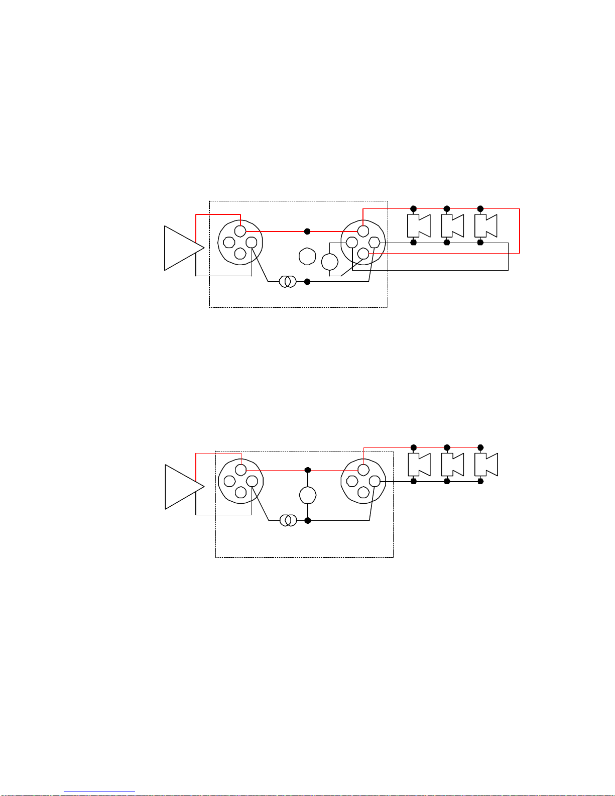
13
Audio connections 4 wire system.
1+
1-2-
2+
1+
1-2-
2+
V
V
I
S
R
ECM channel connections
Speakon
Connector
Amp
Speakon
Connector
Audio connections 2 wire system.
1+
1-2-
2+
1+
1-2-
2+
I
S
Speakon
Connector
Speakon
Connector
V
Amp

14
Appendix D
Event Input Description
The ECM has four opto-isolated inputs for monitoring external events. When the
ECM is networked to either a SID or JNR ( refer to enclosed CD ) the events can
be registered on an LCD display. All logged faults can then be printed or stored
to a log file on a PC.
Configuration
Each fault input can be configured to operate in three modes : ♦Disabled.
♦Fault when opto off.
Fault reported when opto-coupler diode is un -powered and
input OK when powered. This is the recommended mode of
operation as a break in the wiring between the contact and
the input will be reported as a fault.
♦Fault when opto on.
Inverse of above.
The status of these inputs is not latched, each input can be assigned an
individual name for easy fault recognition.
15
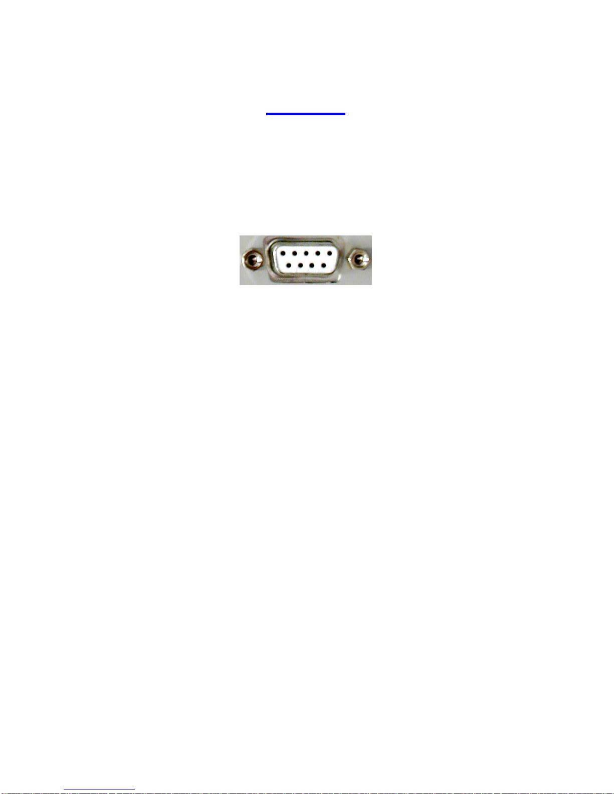
Connectors
Each group of four inputs is provided with a 9-Pin female Dee-type connector.
Pin 1 Input 1 +
Pin 2 Input 2 +
Pin 3 Input 3 +
Pin 4 Input 4 +
Pin 5 12V @ 50mA max
Pin 6 Input 1 -
Pin 7 Input 2 –
Pin 8 Input 3 –
Pin 9 Input 4 –
Shell = Gnd
N.B. If the internal supply is to be used to power the inputs, it is essential that a
good electrical and mechanica l connection be made between the plug and
socket shell as this is used as the ground terminal.

16
Connections
The diagram below shows how a voltage free contact should be wired.
Using an external power supply.
The Opto-diodes can be driven by active outputs as shown below
N.B. If an external supply or active drive is used, careful attention must be taken
over ground routing.
+12V
In +
In -
Gnd
Contact
being
monitored
+12V
In +
In -
Gnd
Contact
being
monitored
12V D.C.
power
supply
+12V
In +
In -
Gnd
Opto off = 0v @0mA
Opto on = 12V @15mA
17
Appendix E
Common Fault Relay
The common fault relay is activated on detection of any fault. It could be used to
enable a sounder or light indicator on detection of a fault, to alert an engineer of
a fault on the system.
Pin 1 Relay Wiper
Pin 2 NC when not in fault
Pin 3 NO when not in fault
Pin 4-9 No connection
The contacts are rated @ 30V 1A
Power Supply
230V 50Hz, the mains fuse ( T500mA 20mm ) is mounted within this connector.
The fuse carrier also contains a spare fuse. To reduce the risk of fire replace the
mains fuse only with the same type.
DC power inlet
There is an optional (24V+/ - 1V @ 1A) input provided above the mains input.
This can be used instead of the mains or as battery backup should the mains fail.
The plug is a standard DC connector with 2.5mm dia, 5.5mm external and 14mm
long. The centre pin is positive.
18
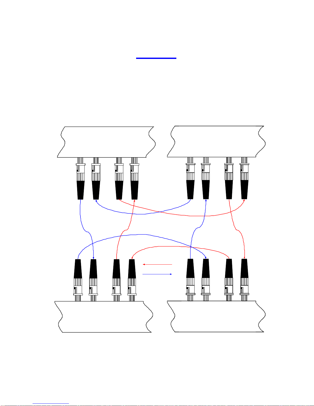
Appendix F
Optical Fibre Connectors
These are ST bayonet connectors operating at a wavelength of 820nm. The fibre
length between units should not exceed 2km (with 2 couplers in line, i.e. for patch
panels). To achieve the required fault tolerance twin fibres loo ps are used, these
should be routed in physically divergent routes and opposite directions, as shown
below.
Rx
PRIMARY
SECONDARY
Tx TxRx
SECONDARY LOOP
PRIMARY LOOP
Rx
PRIMARYSECONDARY
Tx TxRx
Rx
PRIMARYSECONDARY
Tx TxRx
Rx
PRIMARYSECONDARY
Tx TxRx

19
Manufacturers Information
The ECM is manufactured in England by IKON AVS Ltd. Units may be branded
IKON AVS or M+D Design.
For service or warranty advice please initially contact your supplier. Alternatively
contact the manufactures at:-
IKON AVS Ltd
Unit 238 Ikon Trading Estate
Droitwich Road
Hartlebury
Worcestershire
DY10 4EU
Telephone: (44) 01299 250991
Fax: (44) 01299 250983
Website www.ikonavs.com
Technical support e-mail:- support@ikonavs.com
Electromagnetic Compatibility
This equipment has been designed, manufactured and tested to conform to the
European EMC directives EN55103-1 & EN55103-2 for classifications E2 and
E4.
Limitations as to use: 1. The specified equipment is to be mounted into
an earthed, steel equipment rack and not
mounted adjacent to RF transmitting or
receiving equipment.
 Loading...