

IKM Instrutek PM205, PC705M Operating Manual
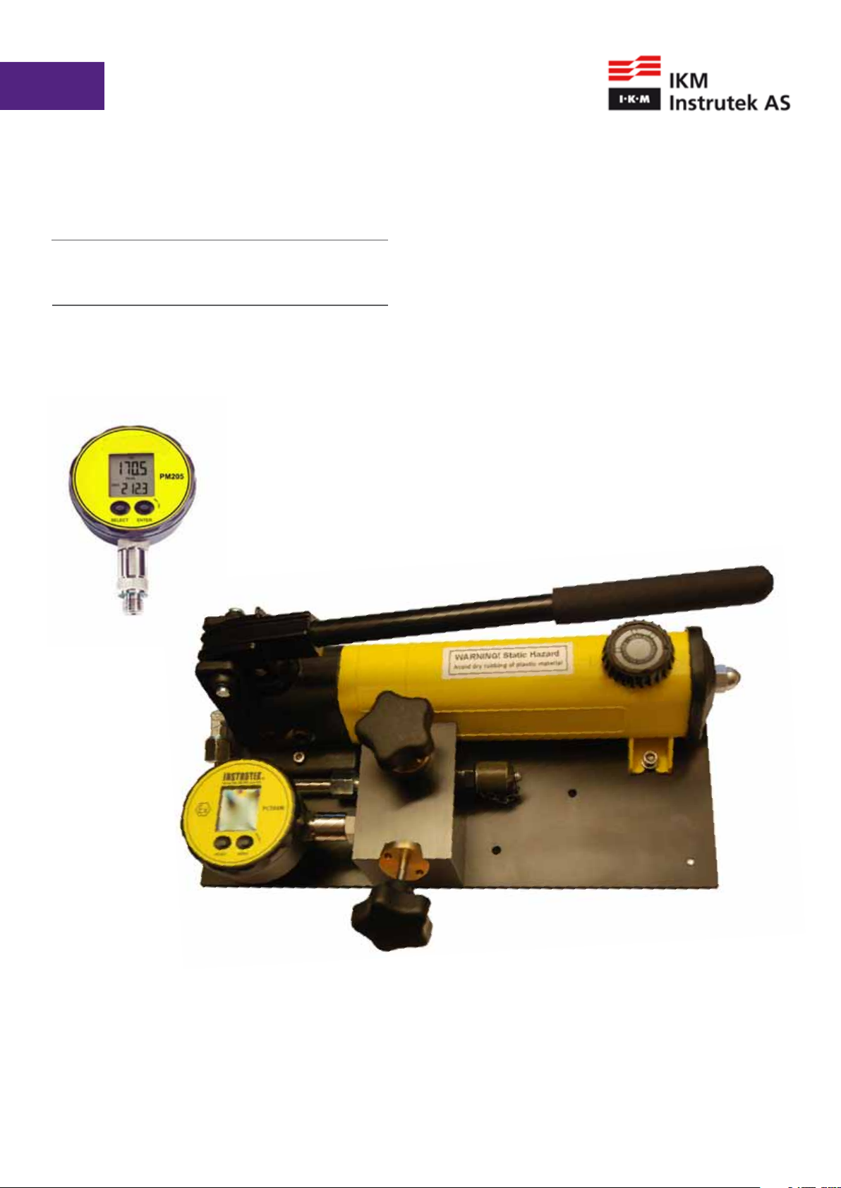
Pressure Calibrator
PM205 / PC705M
User’s manual

PM205 / PC705M User’s manual
2

Thank you for purchasing a IKM Instrutek pressure calibrator. The products are manufactured
by IKM Instrutek AS in accordance with our high quality standards in design, choice of
components and workmanship in order to achieve maximum customer satisfaction.
Designed and manufactured by:
IKM Instrutek AS
Elveveien 28, 3262 Larvik, Norway
Tel.: + 47 33 16 57 00
Fax.: + 47 33 16 57 10
Web.: www.IKM.com
E-mail: IKMinstrutek@IKM.no
IKM Instrutek AS reserves the right to make improvments or alterations to our products
without incurring any responsibility to make the same improvments or alterations to products
previously sold.
IKM Instrutek AS
All rights reserved. No part of this publication may be reproduced, stored in a retrieval system,
or transmitted in any form by any means, electronic, mechanical, photocopying, recording, or
otherwise without the prior permission of IKM Instrutek AS.
All efforts have been made to ensure the accuracy of this handbook. We at IKM Instrutek are
always striving to improve our products and handbooks, therefore we would greatly appreciate
being informed of any errors found in our product or in its manual. The above notwithstaning,
IKM Instrutek can assume no responsibility for any errors in this handbook or of their
consequenses.
Synbol used to identify an action that can cause personal injuri or damage
to equipment.
Always release internal pressure at connectors before disconnecting.
Uncontrolled release of high pressure can result in personal injury and
damage to equipment.
The unit is certified by DNV-GL. Please contact us if a copy of the approval is required.
3

PM205 / PC705M User’s manual
Table of Contents
1.
1.1
1.2
1.3
1.4
1.5
1.6
2.
2.1
2.2
2.3
2.4
2.5
3.
DESCRIPTION OF THE PM205 / PC705M .....................................................................
Calibration label ...........................................................................................................
Certification .................................................................................................................
Warranty .......................................................................................................................
Convention used in this document ............................................................................
Battery change/battery life .........................................................................................
PM205 / PC705M not operating / failed ....................................................................
CONTROL AND INDICATORS .......................................................................................
Display, controls and connections ..............................................................................
Communication PC705M .............................................................................................
Measuring procedure of the peak-mode ...................................................................
Installation ....................................................................................................................
Ranges/calibration ........................................................................................................
SPECIFICATION OF PM205 ...........................................................................................
Page 5
Page 5
Page 5
Page 5
Page 6
Page 6
Page 6
Page 7
Page 7
Page 9
Page 10
Page 10
Page 10
Page 11
4.
4.1
4.2
4.3
5.
5.1
5.2
5.3
6.
6.1
6.2
7.
7.1
7.2
7.3
7.4
8.
LTP1, LOW PRESSURE HAND PUMP ............................................................................
LTP1, Controls and orientation ...................................................................................
Operation of the TP1 ...................................................................................................
LTP1 fault investigation ...............................................................................................
TP1, HAND HELD PRESSURE TEST SYSTEM ................................................................
TP1 controls and orientation ......................................................................................
Operation of the TP1 ...................................................................................................
TP1 fault investigation .................................................................................................
HTP1, HYDRAULIC HAND HELD PRESSURE TEST SYSTEM ........................................
HTP1 controls and orientation ....................................................................................
Operations of the HTP1 ...............................................................................................
PV411 PNEUMATIC/HYDRAULIC HAND-PUMP SYSTEM ...........................................
PV411 controls and orientation ..................................................................................
PV411 pneumatic operation .......................................................................................
PV411 hydraulic operation ..........................................................................................
PV411 fault investigation ............................................................................................
PM205 ACCESSORIES ...................................................................................................
Page 12
Page 12
Page 14
Page 14
Page 15
Page 15
Page 17
Page 17
Page 18
Page 18
Page 19
Page 20
Page 21
Page 22
Page 24
Page 27
Page 27
8.1
9.
9.1
9.2
10.
4
ADAPTERS FOR ITEM UNDER TEST
PC705M .........................................................................................................................
PC705M CONTROLS AND ORIENTATION ....................................................................
OPERATION OFTHE PC705M........................................................................................
CERTIFICATES ................................................................................................................
Page 27
Page 29
Page 29
Page 30
Page 30

1 DESCRIPTION OF THE PM205 / PC705M
The PM205 / PC705M Pressure Calibrator has been designed as a self-contained, portable
pressure meters that have been calibrated to precision pressure equipment traceable to
national standards.
Each unit is marked with:
• Calibration label, next calibration date
• Serial number
• Production year
• Pressure range.
1.1 CALIBRATION LABEL
IKM Instrutek AS certifies that this product meets published specifications at the time of
shipment from the factory. IKM Instrutek AS further certifies that its calibration measurements
are traceable to accredited international standards. Each pressure calibrator has a calibrated
label showing the last date of calibration and the date when the next calibration is due.
Calibration is scheduled annually, unless you believe the unit to be defective, whereupon the
unit will becalibrated after repair and receive a new label showing the date calibrated and the
new calibration-due date. Check the calibrated label to ensure the Pressure Meter Calibrator
has a valid calibration date before using the unit. Calibration must be done by IKM Instrutek AS
or a certified supplier/service center.
1.2 CERTIFICATION
IKM Instrutek AS certifies that the PM205 complies with its published list of specifications at the
time it was manufactured. IKM Instrutek AS also certifies that its calibration measurements are
traceable to Norwegian Accreditation and to the calibration facilities of other International
Standards Organization (ISO) members. IKM Instrutek AS confirms that the PM205 / PC705M
complies with the following standards:
Electromagnetic compatibility as established in the
guidelines of the European Community, EMC 89/336/ EWG .
The following norms are applied:
EN 61000-6-2, EN 61000-6-3.
1.3 WARRANTY
This product is guaranteed free from defects in material and workmanship for one (1) year
from the date of shipment. During this warranty period, IKM Instrutek AS will, at its option,
either repair or replace the PM205 / PC705M should it prove to be defective. The product must
be returned to a service facility designated by IKM Instrutek AS for warranty service or repair.
The foregoing warranty will not apply to defects resulting from improper maintenance by the
purchaser, purchasersupplied software or interfacing, unauthorized modification or misuse,
operation exceeding the environmental specifications for the PM205 / PC705M, or improper site
preparation. No other warranty is expressed or implied by IKM Instrutek AS, and IKM Instrutek
AS shall not be liable for any direct, indirect, special, incidental or consequential damages,
whether based on contract, tort, or any other legal theory.
5

PM205 / PC705M User’s manual
1.4 CONVENTIONS USED IN THIS DOCUMENT
We have provided this section of the Handbook to help you identify noteworthy symbols,
terms and conventions used in this handbook. Look for the following:
Symbol used to identify an
action thatcan cause personal
injury or damage to equipment.
Conformité
Européenne
Terms and definitions:
We define calibration as being able to compare
the ability of the equipment to perform to a
known standard. Pressure calibration provides a
means of quantifying uncertainties in pressure
measurement in order to optimize sensor and/or
system accuracy.
1.5 BATTERY CHANGE / BATTERY LIFE
When the battery starts weakening, a low battery warning (BAT LOW) will appear in the upper
left corner of the display. Battery change: Open the instrument (turn the display ring beyond
the limit stop). Open the battery compartment and change the battery (type CR2430).
Make sure that the O-ring remains embedded in the cover. The battery life is 150 hours in
Peak-mode (at continous operation) and 1000 hours in normal measuring mode.
For PC705M the battery life is approximately 2000 hours in normal measuring mode.
1.6 PM205 / PC705M NOT OPERATING / FAILED
Repairs must be done by manufacturer or supplier certified for service/repair.
Replacement parts must be obtained from the manufacturer.
Manufacturers address:
IKM Instrutek AS
Elveveien 28, 3262 Larvik, Norway
Tel.: + 47 33 16 57 00
Fax.: + 47 33 16 57 10
Web.: www.IKM.com
E-mail: IKMinstrutek@IKM.no
6

2 CONTROLS AND INDICATORS
PM205 / PC705M
Digital Pressure Calibrator
2.1 DISPLAY, CONTROLS AND CONNECTIONS
The PM205 / PC705M has two operating keys. The left key (SELECT) serves to select the
functions and the pressure units. The right key (ENTER) activates the selected function or
pressure unit. The right key is also used to switch between the MAX.- and MIN.-value in both
the Mano- and Peak-mode.
7

PM205 / PC705M User’s manual
Turn-on:
Pressing the SELECT key turns the instrument on.
The instrument subsequently displays the software version (year/week), the full-scale pressure
range, the actual pressure (top display) and the last measured MAX.-value (bottom display).
The instrument has the following functions:
RESET: Max.-/Min.-value and Peak-value are set to the actual pressure
OFF: Turns off the instrument
MANO: Releases the following functions:
PEAK off: Normal measuring mode with 2 measurements per second
PEAK on: Fast measuring mode with 5000 measurements per second
ZERO SEt: Sets a new Zero reference
ZERO rES: Sets the Zero to factory setting
CONT on: Deactivates the automatic turn-off function
CONT off: Activates the automatic turn-off function (the instrument turns off 15 minutes
after the last key function)followed by the unit selection.
PM205: bar, mbar, hPa, kPa, MPa, PSI, kp/cm²
PC705M: bar, mbar, hPa, kPa, MPa, PSI, kp/cm², cm-H2O, mH2O, inH2, ftH2O, mmHg, inHg
Example: Setting a new Zero Reference:
--> Turn on the instrument by shortly pressing the SELECT-key.
--> Wait for the instrument’s measuring mode (approx. 3 seconds).
--> Press the SELECT-key 3 times: MANO appears.
--> Press ENTER: PEAK on or PEAK off appears.
--> Press SELECT: ZERO SEt appears.
--> Press ENTER: The new Zero reference is set. The
instrument returns to the measuring mode.
Example: Setting new pressure unit (mbar).
--> Turn on the instrument by shortly pressing SELECT.
--> Wait for the instrument`s measuring mode (≈ 3 s).
--> Press the SELECT-key 3 times: MANO appears.
--> Press ENTER: ZERO SEt appears.
--> Press SELECT: ZERO rES appears.
--> Press SELECT: CONT on or CONT off appears.
--> Press SELECT: bar appears.
--> Press SELECT. mbar appears.
--> Press ENTER: The new pressure unit (mbar) is set.
The instrument returns to the measuring mode.
Display of the Minimum Pressure Value
When in the measuring mode (Display: Actual Pressure and Max.- value), you may display the
Min.-value for 5 seconds by shortly pressing the ENTER-key.
8

Notes:
1) The functions and units can also be called up by keeping the SELECT-key depressed.
Releasing the key enables the displayed function or unit to be activated with the ENTER-key.
2) If the selected function or unit is not activated within 5 seconds with the ENTER-key,
PM205 / PC705M returns to the measuring mode without changing any settings.
3) Turning PM205 / PC705M on and off does not influence any of the previous settings.
4) If the PEAK on or CONT on function is activated, it is indicated with a flashing sign on the
display.
5) If a pressure can not be represented on the display, OFL (overflow) or UFL (underflow)
appears on the display.
6) If the actual pressure goes beyond the measuring range, the last valid pressure value starts
flashing on the display.
2.2 COMMUNICATION PC705M
Interface (RS485)
The interface converter K-103A (RS232) or K-114A (USB) can be connected at the back of the
manometer (Fischer plug Series 103), allowing the data transfer to the PC.
The corresponding PC software can be found on our web site.
Note: The RS485 interface may only be used outside the zone with a potentially explosive
atmosphere!
The connection at the rear for the RS485 interface may only be used outside the zone with a
potentially explosive atmosphere.
Due to the internal capacitances only a safe maximum voltage of Um = 6,3 V may be applied
and the power of 0,9 W may not be exceeded.
This guarantees that the capacitance limit for the basic voltage level is not exceeded on
reintroducing the equipment to the hazardous zone.
The battery may be changed inside the zone with a potentially explosive atmosphere.
The following battery type must be used in explosive atmospheres: Renata CR2430 or
CR2430MFR
Do not conduct such processes in close proximity, which generate charged particles
(air ioniser, high-voltage electrodes, etc.)
9
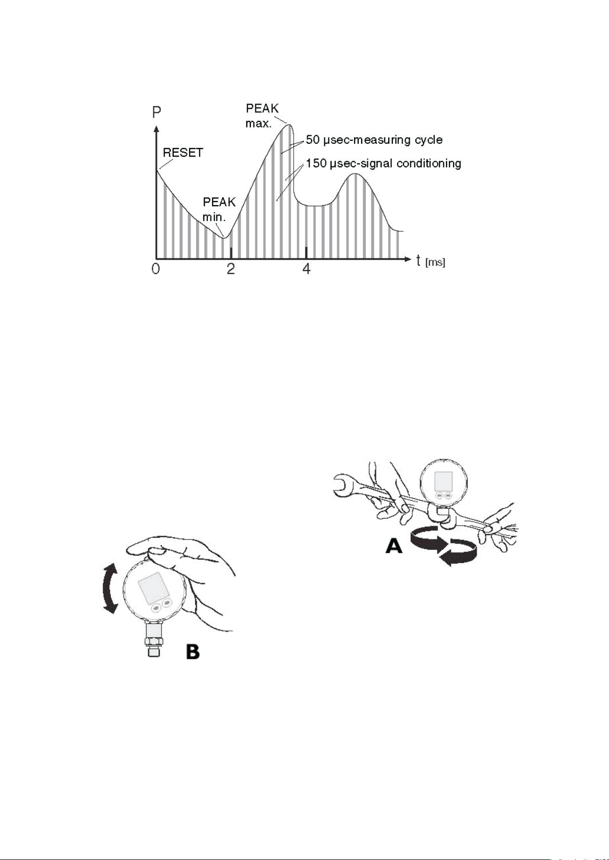
2.3 MEASURING PROCEDURE OF THE PEAK-MODE
PM205 / PC705M User’s manual
2.4 INSTALLATION
Ref. A) Screw the G ¼“ male port of PM205 / PC705M into the choosen pressure pump and
tighten using the lower hexagon of the transducer. Loosen the upper hexagon and rotate the
PM205 / PC705M to the desired position. Retighten. Ref. Chapter 4 to 7 for further details.
Ref. B) The face of the PM205 / PC705M can be rotated trough 355 Degrees. This feature allows
the PM205 / PC705M to be mounted in all possible positions; vertical, horizontal or upside
down.
2.5RANGES / CALIBRATION
The factory setting of the Zero for the ranges -1…3 bar, -1…30 bar or -1...60 bar is at 0 bar
absolute. For sealed gauge pressure measurements, activate “Zero Set” at ambient pressure.
Instruments with ranges > 60 bar are calibrated in a sealed gauge mode at ambient pressure.
10
 Loading...