

Ikelite SLR-DC 6855 Instruction Manual
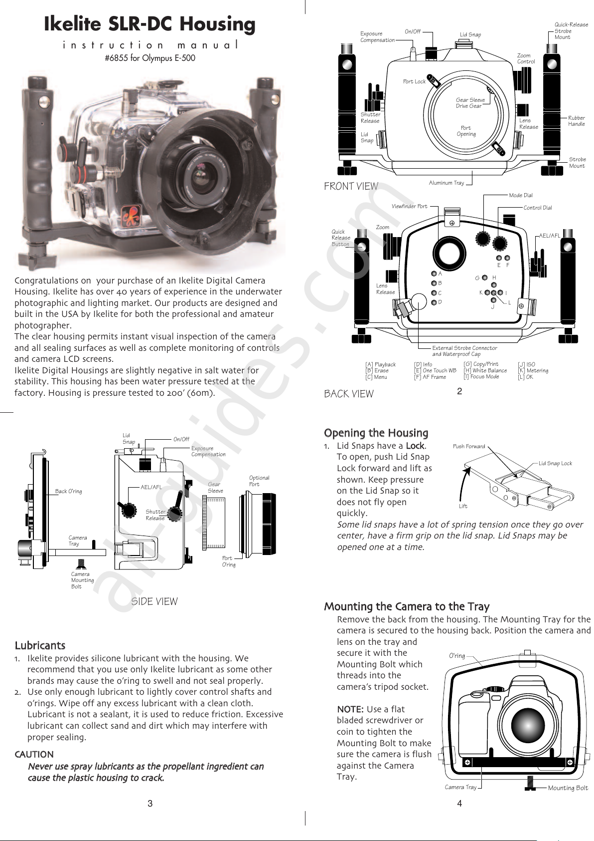
Congratulations on your purchase of an Ikelite Digital Camera
Housing. Ikelite has over 40 years of experience in the underwater
photographic and lighting market. Our products are designed and
built in the USA by Ikelite for both the professional and amateur
photographer.
The clear housing permits instant visual inspection of the camera
and all sealing surfaces as well as complete monitoring of controls
and camera LCD screens.
Ikelite Digital Housings are slightly negative in salt water for
stability. This housing has been water pressure tested at the
factory. Housing is pressure tested to 200’ (60m).
Ikelite SLR-DC Housing
instruction manual
#6855 for Olympus E-500
2
Strobe
Mount
R
ubber
H
andle
Quick-Release
Strobe
Mount
G
ear Sleeve
D
rive Gear
Zoom
Control
Lid Snap
Lens
Release
Exposure
Compensation
On/Off
Lid
Snap
Shutter
Release
Port Lock
Aluminum Tray
Port
Opening
Quick
Release
Button
External Strobe Connector
and Waterproof Cap
Viewfinder Po r t
[D] Info
[E] One Touch WB
[F] AF Frame
[G] Copy/Print
[H] White Balance
[I] Focus Mode
A
B
C
D
EF
G
H
I
K
L
J
Lens
Release
Zoom
Control Dial
AEL/AFL
Mode Dial
[A] Playback
[B] Erase
[C] Menu
[J] ISO
[K] Metering
[L] OK
FRONT VIEW
BACK VIEW
3
SIDE
VIEW
Camera
Tray
Camera
Mounting
Bolt
Gear
Sleeve
Port
O'ring
Optional
Port
Lid
Snap
Shutter
Release
Back O’ring
On/Off
AEL/AFL
Exposure
Compensation
LLuubbrriiccaanntts
s
1. Ikelite provides silicone lubricant with the housing. We
recommend that you use only Ikelite lubricant as some other
brands may cause the o’ring to swell and not seal properly.
2. Use only enough lubricant to lightly cover control shafts and
o’rings. Wipe off any excess lubricant with a clean cloth.
Lubricant is not a sealant, it is used to reduce friction. Excessive
lubricant can collect sand and dirt which may interfere with
proper sealing.
CCAAUUTTIIOON
N
NNeevveerr uussee sspprraayy lluubbrriiccaannttss aass tthhee pprrooppeellllaanntt iinnggrreeddiieenntt ccaan
n
ccaauussee tthhee ppllaassttiicc hhoouussiinngg ttoo ccrraacckk.
.
4
MMoouunnttiinngg tthhee CCaammeerraa ttoo tthhee TTrraay
y
Remove the back from the housing. The Mounting Tray for the
camera is secured to the housing back. Position the camera and
lens on the tray and
secure it with the
Mounting Bolt which
threads into the
camera’s tripod socket.
NNOOTTEE:
:
Use a flat
bladed screwdriver or
coin to tighten the
Mounting Bolt to make
sure the camera is flush
against the Camera
Tray.
O‘ring
Mounting Bolt
Camera Tray
OOppeenniinngg tthhee HHoouussiinng
g
1. Lid Snaps have a
LLoocck
k
.
To open, push Lid Snap
Lock forward and lift as
shown. Keep pressure
on the Lid Snap so it
does not fly open
quickly.
Some lid snaps have a lot of spring tension once they go over
center, have a firm grip on the lid snap. Lid Snaps may be
opened one at a time.
Lift
Push For ward
Lid Snap Lock
All manuals and user guides at all-guides.com
all-guides.com
6
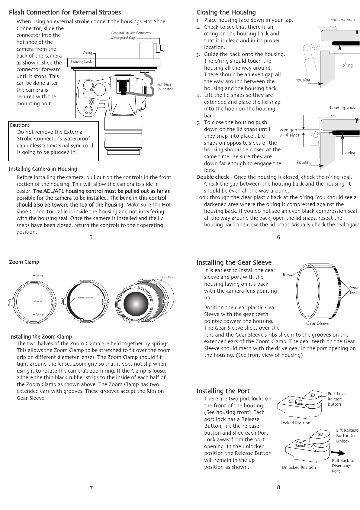
CClloossiinngg tthhee HHoouussiinng
g
1. Place housing face down in your lap.
2. Check to see that there is an
o’ring on the housing back and
that it is clean and in its proper
l
ocation.
3. Guide the back onto the housing.
T
he o’ring should touch the
housing all the way around.
There should be an even gap all
the way around between the
h
ousing and the housing back.
4. Lift the lid snaps so they are
extended and place the lid snap
into the hook on the housing
back.
5. To close the housing push
d
own on the lid snaps until
they snap into place . Lid
snaps on opposite sides of the
housing should be closed at the
same time. Be sure they are
down far enough to engage the
lock.
DDoouubbllee cchheecck
k
- Once the housing is closed, check the o’ring seal.
Check the gap between the housing back and the housing, it
should be even all the way around.
Look through the clear plastic back at the o’ring. You should see a
darkened area where the o’ring is compressed against the
housing back. If you do not see an even black compression seal
all the way around the back, open the lid snaps, reseat the
housing back and close the lid snaps. Visually check the seal again.
o’ring
housing back
housing back
housing
housing
o’ring
even gap
all 4 sides
5
FFllaasshh CCoonnnneeccttiioonn ffoorr EExxtteerrnnaall SSttrroobbees
s
When using an external strobe connect the housings Hot Shoe
Connector, slide the
connector into the
hot shoe of the
c
amera from the
back of the camera
as shown. Slide the
connector forward
until it stops. This
can be done after
t
he camera is
secured with the
mounting bolt.
O'ring
H
ousing Back
E
xternal Strobe Connector
Waterproof Cap
H
ot Shoe
Connector
CCaauuttiioonn:
:
D
o not remove the External
Strobe Connector’s waterproof
cap unless an external sync cord
is going to be plugged in.
IInnssttaalllliinngg CCaammeerraa iinn HHoouussiinng
g
Before installing the camera, pull out on the controls in the front
section of the housing. This will allow the camera to slide in
easier.
TThhee AAEELL//AAFFLL hhoouussiinngg ccoonnttrrooll mmuusstt bbee ppuulllleedd oouutt aass ffaarr aas
s
ppoossssiibbllee ffoorr tthhee ccaammeerraa ttoo bbee iinnssttaalllleedd..TThhee bbeenndd iinn tthhiiss ccoonnttrrool
l
sshhoouulldd aallssoo bbee ttoowwaarrdd tthhee ttoopp ooff tthhee hhoouussiinngg.
.
Make sure the Hot-
Shoe Connector cable is inside the housing and not interfering
with the housing seal. Once the camera is installed and the lid
snaps have been closed, return the controls to their operating
position.
7
IInnssttaalllliinngg tthhee ZZoooomm CCllaammp
p
The two halves of the Zoom Clamp are held together by springs.
This allows the Zoom Clamp to be stretched to fit over the zoom
grip on different diameter lenses. The Zoom Clamp should fit
tight around the lenses zoom grip so that it does not slip when
using it to rotate the camera’s zoom ring. If the Clamp is loose,
adhere the thin black rubber strips to the inside of each half of
the Zoom Clamp as shown above. The Zoom Clamp has two
extended ears with grooves. These grooves accept the Ribs on
Gear Sleeve.
S
prings
Groove
Rubber Strips
Lens Zoom Grip
Springs
ZZoooomm CCllaammp
p
8
IInnssttaalllliinngg tthhee GGeeaarr SSlleeeevve
e
It is easiest to install the gear
sleeve and port with the
housing laying on it’s back
with the camera lens pointing
up.
Position the clear plastic Gear
Sleeve with the gear teeth
pointed toward the housing.
The Gear Sleeve slides over the
lens and the Gear Sleeve’s ribs slide into the grooves on the
extended ears of the Zoom Clamp. The gear teeth on the Gear
Sleeve should mesh with the drive gear in the port opening on
the housing. (See front view of housing)
Gear Sleeve
Rib
Gear
Teeth
IInnssttaalllliinngg tthhee PPoorrt
t
There are two port locks on
the front of the housing.
(See housing front) Each
port lock has a Release
Button, lift the release
button and slide each Port
Lock away from the port
opening. In the unlocked
position the Release Button
will remain in the up
position as shown.
Port Lock
Release
Button
Lift Release
Button to
Unlock
Pull Back to
Disengage
Port
Unlocked Position
Locked Position
All manuals and user guides at all-guides.com
 Loading...