

Ikelite SLR-DC 6812.31 Instruction Manual
I
K
E
L
I
T
E
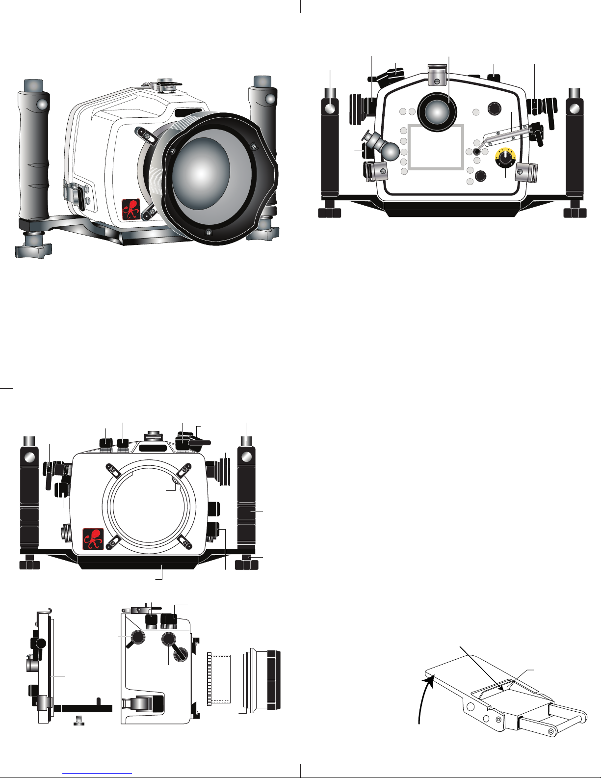
Strobe
Mount
Rubber
Handle
Quick-Release
Strobe
Mount
Lid
Snap
Port Lock
Aluminum Tray
I
KELITE
Gear Sleeve
Drive Gear
Port
Opening
Fn/DOF Preview
Power
Switch
Shutter
Release
Flash +/-
Zoom
SubCommand
Dial
Release Mode
Dial Lock Rel.
Focus Mode
Selector
Quick
R
elease
Button
V
iewfinder Port
[D] Protect
[E] Ext. Strobe Conn.
& Waterproof Cap
[F] Playback Zoom-Out
[G] Playback Zoom-In
[H] OK Button
[I] AF-ON
[J] Main Command Dial
A
L
ens
Release
A
E-L
AF-L
[A] Playback
[B] Delete
[C] MENU
[K] Multi-Selector Button
[L] Multi-Selector Up
[M] Multi-Selector Left
Release
Mode
Dial
C
F
H
L
G
J
M
K
N
B
D
I
O
P
Q
R
S
[N] Multi-Selector Right
[O] Multi-Selector Down
[P] Flash Exposure/
Control Dial
[Q] Live View Button
[R] AF-Area Mode Selector
[S] Info Button
W
B/ISO
QUAL
Mode
+
/-
E
TTL
1
-1
-1
F
-2
-3
MAN
Camera
Tray
Camera
Mounting
Bolt
Gear
Sleeve
Port
O'ring
Port Lock
Optional
Port
Lid
Snap
Back O’ring
AE-L/AF-L
Power Switch
Mode, +/-
Shutter
Release
Lift
Push For ward
Lid Snap Lock
Ikelite SLR-DC Housing
i n s t r u c t i o n m a n u a l
#6812.31 for Nikon D300s
Congratulations on your purchase of an Ikelite Digital Camera
Housing. Ikelite has over 45 years of experience in the underwater
photographic and lighting market. Our products are designed and
built in the USA by Ikelite for both the professional and amateur
photographer.
The clear housing permits instant visual inspection of the camera
and all sealing surfaces as well as complete monitoring of controls
and camera LCD screens.
Ikelite Digital Housings are slightly negative in salt water for
stability. This housing has been water pressure tested at the
factory. Housing is pressure tested and warranted to 200’ (60m).
BACK VIEW
2
FRONT VIEW
SIDE VIEW
3
IInniittiiaall CCaammeerraa SSeettuupp
- Insert a fully charged battery.
- Insert memory card (1GB or greater capacity recommended).
- Set the mode dial to “M” manual.
- Set shutter speed to 1/60th second or 1/125th second for fast
moving subjects.
- Set aperture to F8 for general photography or F22 for macro
photography (close-ups).
- Set Image Quality to Fine or RAW.
- Set ISO to Lo1 (100) or 200.
- Set Meter to “center-weighted”.
- Set White Balance to “Auto” or “Flash”.
- Make sure Red-Eye Reduction is NOT enabled.
- Make sure AF-assist illuminator is NOT enabled.
- Set Focus-mode selector to “S” Single-servo.
OOppeenniinngg tthhee HHoouussiinngg
Lid Snaps have a
To open, push Lid Snap Lock forward and lift as shown. Keep
pressure on the Lid
Snap so it does not
fly open quickly.
Some lid snaps
have a lot of
spring tension
once they go over
center, so have a
firm grip on the lid
snap. Lid Snaps
may be opened
one at a time.
LLoocckk
.
4
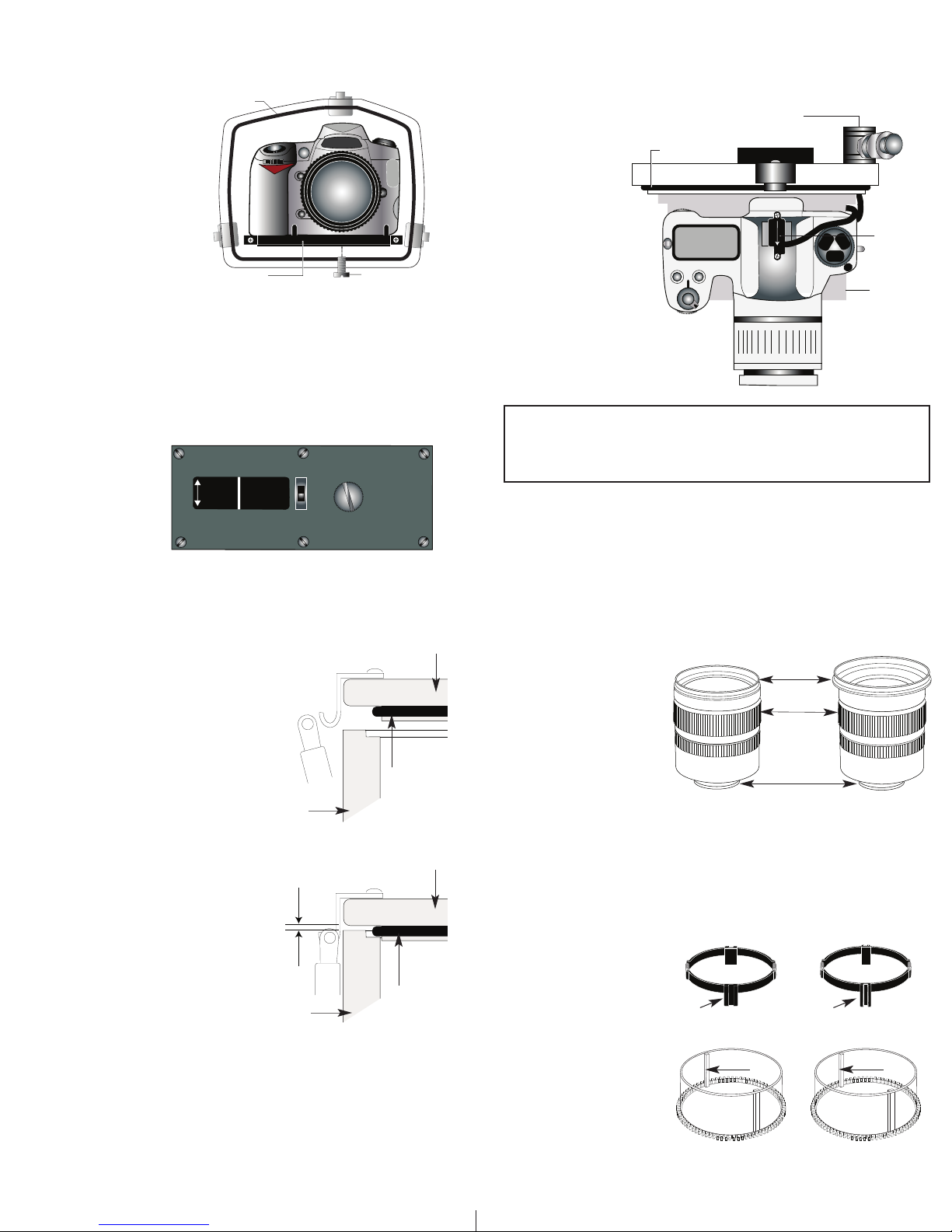
Figure A-Type 1 Lens
IInnssttaalllliinngg tthhee CCaammeerra
1
2
5
1
6
0
/
1
6
1
D
S
D
S
S
e
t
D
S
S
u
b
s
t
r
o
b
e
s
t
o
T
T
L
Mo
d
e
5
0/
51
2
0
0
8
0
N
ikon
D300s
O‘ring
Mounting Bolt
Camera Tray
O'ring
H
ousing Back
Hot Shoe
Connector
“slide forward
u
ntil it stops”
E
xternal Strobe Connector
a
nd Waterproof Cap
Mounting
Tray
a
Remove the back from the housing. The mounting tray for the
amera is secured to the housing back. Position the camera and
c
lens on the tray, and
then secure it with the
mounting bolt which
hreads into the
t
camera’s tripod socket.
Use a flathead screwdriver (recommended)
or coin to tighten the
mounting bolt so the
camera bottom is flush
against the tray.
FFllaasshh CCoonnnneeccttiioonn ffoorr EExxtteerrnnaall SSttrroobbees
s
When using an external strobe, connect the housing hotshoe
connector. Slide the connector into the hotshoe mount on the
camera from the back of the camera as shown. Slide the
connector
forward until it
tops. This can
s
be done before
or after the
camera is
ecured with
s
the mounting
bolt.
NNOOTTEE::
Conversion
Circuitry Strobe ID Switch is located on bottom of camera tray.
SSeettttiinngg tthhee CCoonnvveerrssiioonn CCiirrccuuiittrryy SSttrroobbee IIDD SSwwiittcchh..
On the bottom of the camera tray is a switch for setting the DS
Substrobe ID. Set the switch to the Model of DS Substrobe being
used.
• When using dual
strobes of different
models such as a
DS51 and a DS161,
set the ID switch to
DS51 or the smaller
strobe.
5
CClloossiinngg tthhee HHoouussiinngg
1. Place housing face down in your lap.
2. Check to see that there is an o’ring
on the housing back that is clean
and in its proper location.
3. Guide the back onto the housing.
The o’ring should touch the housing
all the way around. There should
be an even gap all the way around
between the housing and the
housing back.
4. Lift the lid snaps so they are
extended and place the lid snap into
the corresponding hook on the
housing back.
5. To close the housing, push
down on the lid snaps until
they snap into place . Lid
snaps on opposite sides of
the housing should be closed
at the same time. Be sure they
are down far enough to engage
the lid-snap lock.
DDoouubbllee cchheecckk
Check the gap between the housing back and the housing, it
- Once the housing is closed, check the o’ring seal.
should be even all the way around.
Look through the clear plastic back at the o’ring. You should see a
darkened area where the o’ring is compressed against the
housing back. If you do not see an even black compression seal
all the way around the back, open the lid snaps, reseat the
housing back, and then close the lid snaps. Visually check the seal
again.
7
even gap
all 4 sides
housing
housing
housing back
housing back
o’ring
o’ring
CCaauuttiioonn:
:
Do not remove the External Strobe Connector’s waterproof cap
unless an external sync cord is going to be plugged in. Do not
remove waterproof cap or sync cord underwater.
IInnssttaalllliinngg CCaammeerraa iinn HHoouussiinng
g
Before installing the camera, pull out on the controls in the front
section of the housing. This will allow the camera to slide in.
Once the camera is installed and the lid snaps have been closed,
return the controls to their operating position.
6
PPrreeppaarriinngg ttoo IInnssttaallll ZZoooomm CCllaammpp && GGeeaarr SSlleeeevvee
Determine the type
of lens being used
on the camera.
Type 1 Lenses have
a lens opening that
is NOT larger in
diameter than the
((FFiigg.. 11))
zoom ring.
Type 2 Lenses have a lens
.
Type 1 lens Type 2 lens
(Figure 1) (Figure 2)
opening that IS larger in diameter than the zoom ring.
lens
opening
zoom
ring
bayonet
mount
((FFiigg.. 22))
ZZoooomm CCllaammppss && GGeeaarr SSlleeeevveess IInncclluuddeedd wwiitthh HHoouussiinngg
There are 2 different
Zoom Clamps and
Gear Sleeves
provided with the
housing. Start with
the suggested Zoom
Clamp and Gear
Sleeve depending
on the Type of
lens being used.
((FFiigg.. AA oorr BB))
See
Normally used with
Type 1 lens (Fig.1)
#9059.8 small diameter clamp:
For use with #0073 sleeve
wide
grooved
extension
small diameter zoom clamp
+
tabs
thick ribs
#0073 sleeve: Use with
#9059.8
Figure A
8
Normally used with
Type 2 lens (Fig.2)
#5509.28 Package
#9059.9 large diameter clamp:
For use with #0073.1 sleeve
narrow
grooved
extension
large diameter zoom clamp
+
tabs
thin r ibs
#0073.1 sleeve: Use with
#9059.9
Figure B
.
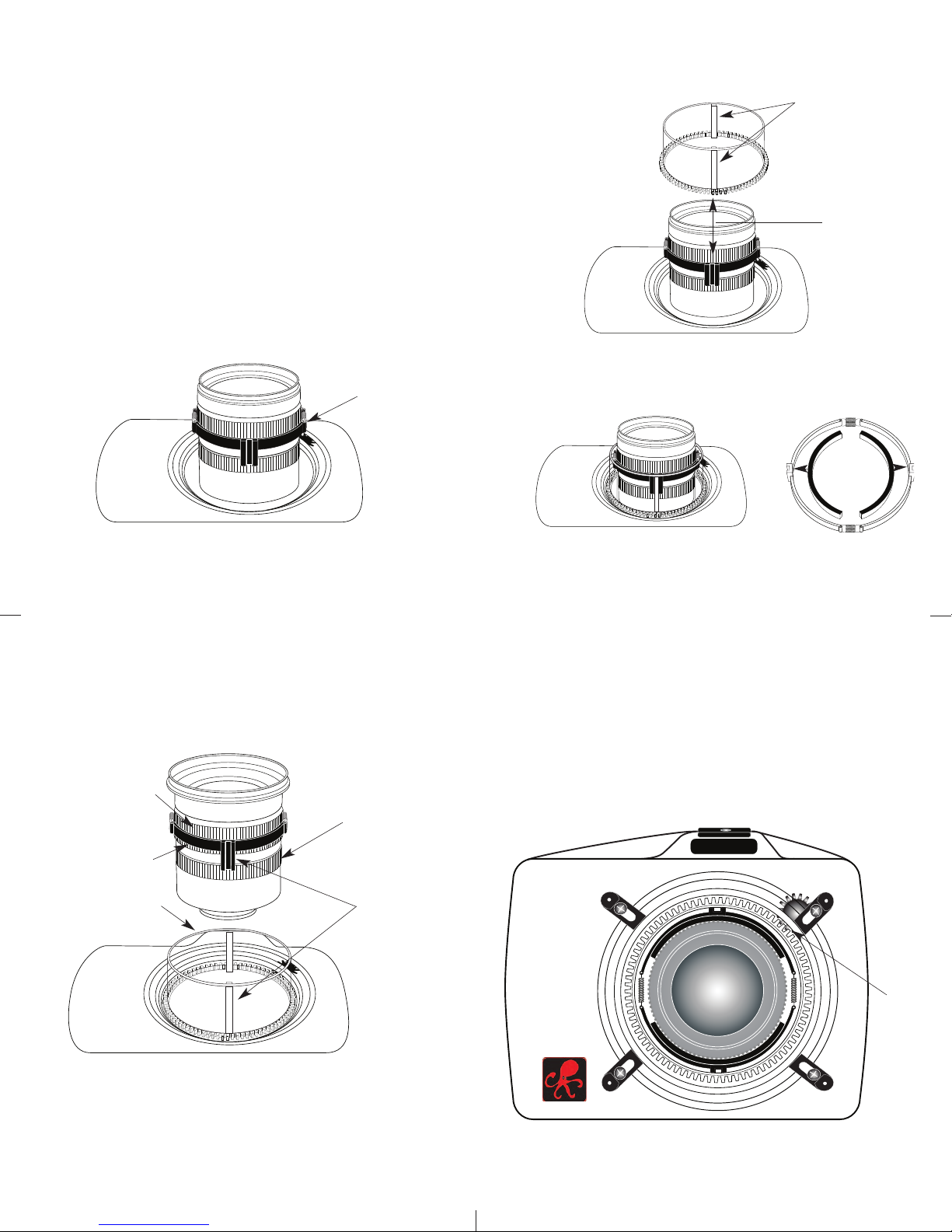
Type 2 Installation: Figure 1
TOP OF HOUSING
IInnssttaalllliinngg tthhee ZZoooomm CCllaammpp && GGeeaarr SSlleeeevvee OOnn tthhee TTyyppee 11 LLeennsseess
IKELITE
Type 1 Installation: Figure A
Type 1 Installation: Figure B
The Zoom Clamp has springs so it can be expanded to fit over
the Zoom Ring of the lens as shown in
Install the Zoom Clamp with the extension tabs toward the rear
element of the lens. After installing the Zoom Clamp and Gear
((FFiigg.. DD && EE))
Sleeve
ing on the lens. If the Zoom Ring and Gear Sleeve do not mesh
R
, install the Lens Port and rotate the Zoom
properly, install the rubber strips (supplied) to the inside
diameter of the Zoom Clamp as shown
Two thicknesses of rubber strips are provided. Start by installing
the thinnest rubber strips. If the Zoom Clamp still is not tight
enough and meshes improperly with the Gear Sleeve, use the
thicker rubber strips. Reinstall the Zoom Clamp, Sleeve, and
Port. Mesh Gear Sleeve teeth with Black Housing Drive Gear
(Fig. G-Page #12)
Type 1 lens
mounted
to camera
((FFiigg.. CC))
((FFiigg.. FF))
.
.
oom
z
ring
TTyyppee 11 LLeennsseess ((ccoonnttiinnuueedd))
Figure D
Gear Sleeve
ibs
r
Align with
oom Clamp
Z
grooved tabs
rubber strips
to inside of
c
a
lamp
pply
Figure C
9
IInnssttaalllliinngg tthhee ZZoooomm CCllaammpp && GGeeaarr SSlleeeevvee OOnn TTyyppee 22 LLeennsseess
Due to the larger diameter lens opening on Type 2 lenses, the
Zoom Clamp and Gear Sleeve need to be installed from the rear
(bayonet end) of the lens. Use the housing Lens Release Control
and remove the camera lens from the camera body, after the
camera and lens have been installed in the housing.
Lens Zoom Ring
Zoom Clamp
Gear Sleeve
Lens Manual
Focus Ring
Zoom Clamp
grooved
tabs with
Gear Sleeve
Align
ribs
Figure E
Figure F
10
NNOOTTEE::
Before installing the lens port and checking operation, make sure
the teeth on the Gear Sleeve mesh with the teeth on the housing
Drive Gear
((FFiigg.. GG))..
Gear Sleeve in place. After installing the port, rotate the housing
Zoom Control Knob to see that the Gear Sleeve is properly
rotating the lens Zoom ring.
When the port is installed, it will lock the
Type 2 lens
MMaannuuaall FFooccuussiinngg NNoottee::
Ikelite DSLR housings are designed for auto-focus DSLR
cameras and lenses. Manual focusing is not recommended. If
you desire to manually focus a lens, the zoom clamp must be
moved onto the lens Manual Focus Ring and you must use the
housing zoom control knob to manually focus. This will result in
loss of zoom capability.
11
Figure G
12
Mesh
Gear Sleeve
teeth with
Black Housing
Drive Gear
 Loading...