

Page 1
Digital Housing
Supp le me nt al I ns tr uc ti on s
6242.95 Canon S95 ULTRAcompact
Size and Weight
Width ......................6.4 in. (163mm) including controls
Height ....................4.6 in. (117mm) including controls
Depth ......................3.3 in. (84mm) including controls & lens port
Weight ....................1.4 lb (635g)
Buoyancy ................Neutrally buoyant underwater
Page 2

Initial Camera Setup
- Set camera mode switch to “Av” Aperture Priority.
- Set White Balance to auto “AWB.”
- Set Light Metering to “Center-Weighted Avg.”
- Set ISO to 80.
- Set Flash to forced ON (flash always fires) “Lightning Bolt.”
- Set Review to “5 Seconds.”
- Set AF-assist beam to “Off.”
- Set Red-Eye Correction and Red-Eye Lamp to “Off.”
- Set AF Frame to “Center” and Servo AF to “Off.”
- Set AF-Point Zoom to “Off.”
- If the "Shortcut/Print" button is not assigned, functions of the rear control
dial can be accessed through the housing by holding down the
"Shortcut/Print" button and using the left/right buttons of the rear control
cluster.
- The camera does NOT operate with TTL “automated” flash when in the
“M” manual mode. “M” manual mode should NOT be used with the AF35
strobe.
- You can assign different camera functions such as ISO, WB, Metering,
AEL, and AFL to the “Short Cut” button and then change those settings
using the arrow buttons. Refer to your camera owner’s manual for
additional information.
- In Manual mode, the Control Ring will operate the aperture setting.
Press the Ring Function button and set to +/- / Tv to change shutter
speed; set to “STD” to adjust aperture.
- Camera functions can be assigned to the Control RIng by pressing the
Ring Function button. Additional functions include ISO, +/- Exp./Tv, MF
Manual Focus, WB white balance, and Step Zoom. Depress the Ring
function button until the desired function is highlighted in the camera
LCD screen. Once the function is highlighted, it can be adjusted using
the Control
Ring.
2
Page 3
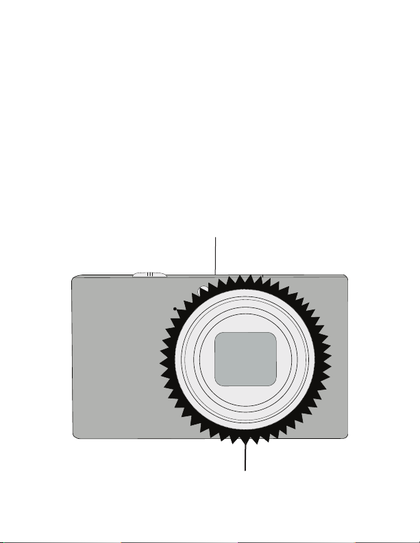
Attaching Control Ring Gear (see illustration below)
CanonCanon
S95
Press the supplied Control Ring Gear over the camera’s control ring
before installing the camera in housing. The gear is a “press fit” and
goes on either way. Make sure to test it’s function once installed.
When installing the camera in housing, make sure that the Control Ring
gear meshes properly with the housing gear.
- Additional Control Ring Gear 0099.23 available through an Ikelite dealer.
Camera Illustration
n Button
tio
ing Func
(loc
R
ted
a
on camera
)
p
to
Control Ring Gear (properly installed)
3
Page 4

Parts of the Housing - Front View
Mode Dial
Shutter Button
Zoom Lever
Control Ring
Power Button
Ring Function
Lens Port
Tray Mount
4
Page 5

ULTRAcompact
Made in USA
I K E L I T E
46
3
7
1
2
5
9
8
Parts of the Housing - Back View
Latch
Lanyard
1. Short Cut
2. Playback
3. Exposure Comp. ,
4. Macro , MF,
5. FUNC./SET
6. Flash ,
7. Single Erase ,
8. Display
9. Menu
5
Page 6

External Accessory Lenses
Ikelite W-20 Wide-Angle Conversion Lens #6420
The front of the lens port accepts the #6420 W-20
and other 67mm threaded wide angle or macro
lenses without the need for an adapter. An external
wide angle conversion lens increases angle of
coverage so you can get much closer to the
subject while still fitting everything in the frame.
Vignetting will occur at widest angle camera lens
setting with these lenses. Zoom in 2 or 3 times to
eliminate, or crop the image in post-processing.
NOTE: Accessory 67mm macro lenses or diopters designed for underwater
use may also be attached directly to the front of the housing port. Bayonet
mount lenses cannot be used with this housing.
Ikelite W-20 Conversion Lens
Canon Compatibility S90 Note:
The Canon Powershot S90 camera body varies slightly by camera
thickness and pushbutton placement. Rear and top pushbutton controls
will be slightly off-center but operational when using the S90 camera in
the S95 housing.
Alternative Ikelite Housing #6242.90 is configured specifically for the
Canon S90 camera.
6
Page 7

AF35 Strobe Package #4035
i
k
e
l
i
t
e
3
5
A
F
i
ke
l
i
t
e
A
U
T
O
F
L
A
S
H
Ikelite strobes are much more powerful, recycle
more quickly, and eliminate more backscatter
than the camera's built-in flash.The AutoFlash
AF35 (pictured at right) is an easy and
affordable way to add a strobe to your system.
The AF35 is effective up to approximately 5 feet
(1.5m) from the subject and restores the colors
that are otherwise lost.
The AF35 is a great compliment, and an
effortless, affordable way to add a flash to your
new Ikelite point and shoot camera system.
Everything you need to get started is in the box.
Just attach it to the bottom of your housing and
start taking pictures!
AF35 AutoFlash kit includes:
- AF35 strobe
- Flex arm
- AutoFlash sensor
- Handle with rubber grip
- Tray (single or dual)
- Mounting hardware
A full range of accessories is available to support your housing. Please
visit http://www.ikelite.com/web_two/can_s95.html to see the most
current information about recommended accessories for your housing.
7
Page 8

Ikelite Underwater Systems
50 West 33rd Street
Indianapolis, IN 46208 USA
www.ikelite.com
#6242.95_Canon_S95-04-0611
 Loading...