

Ikelite pdf #4104.6 ..... Nikonos TTL Cord Film Camera, 4104.6 Instruction Manual
II kk ee ll ii tt ee SS ii nn gg ll ee CC oo rr dd 44 1100 44 .. 66
i n s t r u c t i o n m a n u a l
FFoorr NNiikkoonnooss SSttyyllee HHoouussiinngg ccoonnnneeccttoorrss
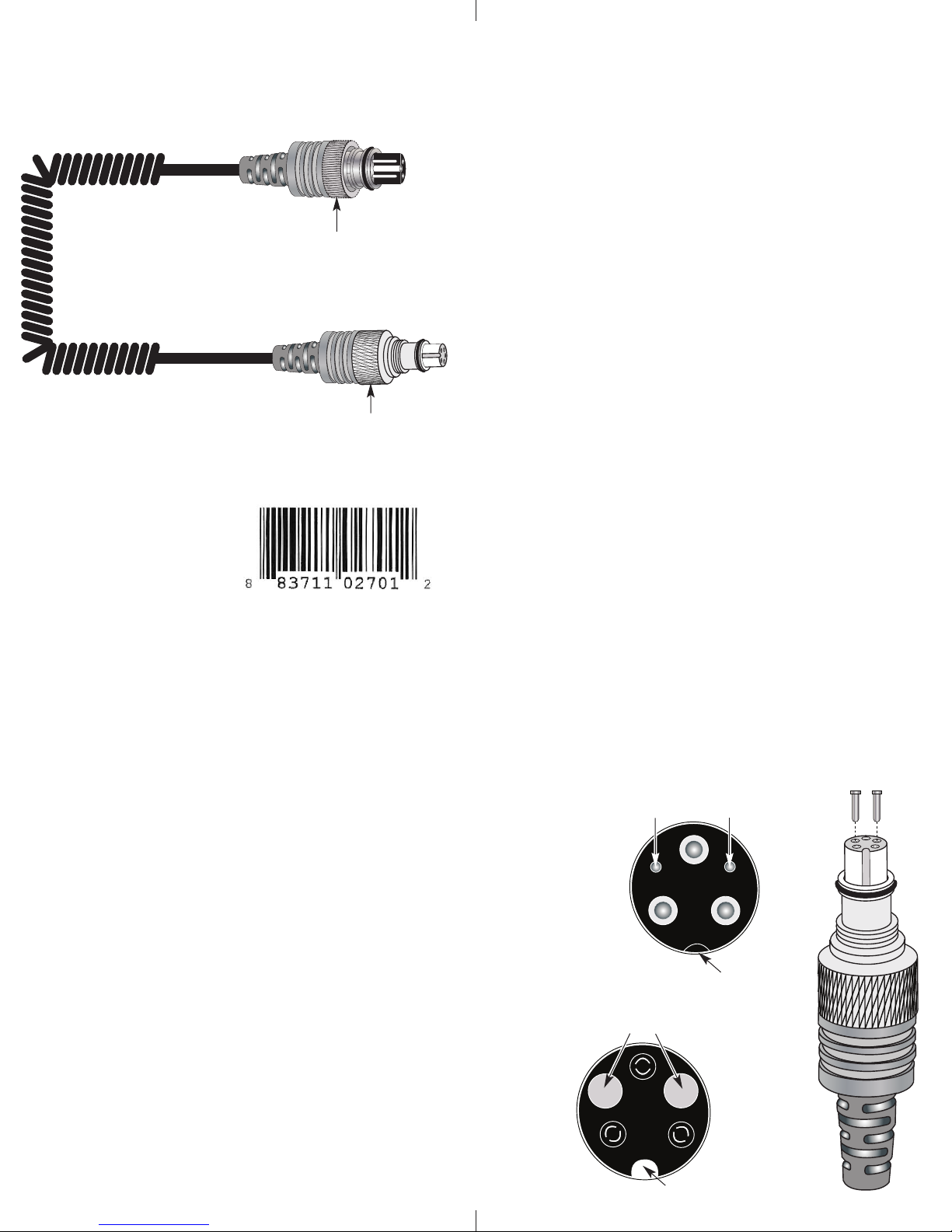
Ikelite Style Connector
Retaining Ring
Nikonos Style Connector
SSiinnggllee SSyynncc CCoorrdd ##44110044..66
Connect one (1) Ikelite Substrobe to a Nikonos IV, V, RS, or
suitable FILM camera housing that utilizes the Nikonos flash socket
for external strobe connection. Different model Substrobes can be
combined. The strobes will fire in TTL automatic or manual
exposure modes using the
Nikonos V or RS. Strobes will
only work in the manual mode
with the Nikonos IV or camera
housings.
Retaining Ring
OONNLLYY IIKKEELLIITTEE TTTTLL SSUUBBSSTTRROOBBEESS CCAANN BBEE CCOONNNNEECCTTEEDD.
DDOO NNOOT
T
use the TTL cord on a non TTL strobe; you will damage
.
the camera.
DDOO NNOOT
T
emove the sync cord from the strobe or camera
r
underwater or when wet. Connections are NOT waterproof when
disconnected underwater.
DDOO NNOOT
T
leave the cord connected for prolonged periods or the
cord may freeze to the strobe, or camera. After each dive,
disconnect the cord and lightly lubricate the connector threads.
NEVER use spray lubricant. Use ONLY Ikelite lubricant.
CCoonnnneeccttiinngg ttoo tthhee CCaammeerraa oorr HHoouussiinngg BBuullkkhheeaadd
. Make sure all components are dry. Clean and lightly
1
lubricate the stem shaft, o-ring and retaining ring threads.
Check the stem o-ring for nicks or cuts.
2. Align the Index Groove (Diagram A - Page 4) with the Index Post
(Diagram B - Page 4) in the flash socket, and insert the stem into
the flash socket.
3. Rotate the retaining ring counter clockwise until it mates with
the flash socket threads. Then, carefully rotate retaining ring
clockwise and thread it into the flash socket until snug
.
CCoonnnneeccttiinngg ttoo IIkkeelliittee TTTTLL SSuubbssttrroobbeess
WWhheenn ccoonnnneeccttiinngg DDuuaall SSttrroobbeess,, ccoonnnneecctt sseeccoonnddaarryy ssttrroobbe
ttoo tthhee ccoorrdd wwiitthh tthhee rreedd bbaanndd.
1. Make sure all components are dry.
2. Clean and lightly lubricate the stem o-ring and the strobe
connector threads. Check the o-ring for nicks or cuts.
3. Note the positioning of the receptacles and pins. Properly align
the end of the sync cord and insert into the strobe bulkhead.
4. Hand-tighten the Retaining ring on the sync cord.
5. Push the connector body further into the strobe connector
and continue to tighten the Retaining Ring.
.
2
e
HHoouussiinngg BBuullkkhheeaadd CCoommppaattiibbiilliittyy
Over the years various housing manufacturers have introduced a
variety of "Nikonos-style" bulkheads with variations on the original
contact design. The plug end on this TTL Adapter has been
designed to prevent damage by some European housings with rigid
contacts in place of the traditional spring-loaded style.
This design may exhibit intermittency with some more traditional
Nikonos-style bulkheads. Two gold plated pins have been provided
to eliminate this intermittency. These pins should only be used in
conjunction with bulkheads featuring two spring-loaded contacts.
To see if your housing has spring-loaded contacts, use an
open-ended paper clip to gently push down on the contacts shown
in Diagram A - page 4. Very little pressure is needed to check the
contacts. If the contacts ARE spring-loaded, proceed to the
directions on page 5 for inserting the included gold plated pins.
These pins are specifically recommended for use with the
Nikonos-style bulkhead featured on Nauticam housings.
If your housing does NOT feature spring-loaded contacts, DO NOT
insert the included pins into your plug end. Doing so may cause
damage to your plug and/or bulkhead.
TTrroouubblleesshhoooottiinngg//IInnsseerrttiinngg PPiinnss
- If intermittent or loss of TTL operation occurs, insert the 2
gold plated pins into the Nikonos Connector End corresponding
receptacles as shown below. With the Index Groove at the bottom,
the pins should be at the 10 and 2 o’clock positions. Once the pins
are installed they should not be removed.
- Connect the Adapter to the housing bulkhead (See page 2).
DDiiaaggrraamm AA
NNiikkoonnooss HHoouussiinngg BBuullkkhheeaad
Spring-loaded Contacts
DDiiaaggrraamm BB
NNiikkoonnooss CCoonnnneeccttoorr EEnnd
Gold-Plated Pins properly inserted in Receptacles
d
d
Index Post
Gold-Plated Pins
3
Index Groove
4

IIkkeelliittee LLiimmiitteedd WWaarrrraanntty
All Ikelite products are warranted against any manufacturing
defects for a period of one year from the original date of purchase.
Defective products should be returned prepaid to Ikelite. Ikelite
will, at its discretion, repair or replace such products, and will
return to customer prepaid. All other claims of any nature are not
covered. Housing is pressure tested and warranted to 200’ (60m)
maximum underwater depth. Except as mentioned above, no other
warranty expressed or implied, applies to this Ikelite product.
y
RReettuurrnniinngg PPrroodduuccttss ffoorr SSeerrvviiccee
Ikelite is most interested in performing any service to ensure that
all products perform as intended. Evidence of purchase date must
be provided to obtain warranty service.
No prior authorization is required. You may return directly to us or
through your dealer. Please include a brief description of the
problem, any relevant e-mail correspondence, and/or instructions
on what you want us to do. Always include name, shipping address,
e-mail address, and phone number inside of the package.
RReettuurrnniinngg PPrroodduuccttss ffoorr SSeerrvviiccee
For the separate international customs documentation form that
you complete to accompany the shipment, please state or
designate that the enclosed products were originally manufactured
in the USA and are being returned to the manufacturer for repair
service. Value of the equipment listed for customs purposes should
be zero.
((oouuttssiiddee tthhee UUnniitteedd SSttaatteess))
HHooww ttoo ccoonnttaacctt IIkkeelliittee iiff nneecceessssaarryy
-mail: ikelite@ikelite.com
E
Phone 317.923.4523
Fax 317.924.7988
You may also want to insure the package.
Send Postage Pre-Paid to:
Ikelite Underwater Systems
ATTN: Repair Dept.
50 West 33 Street
Indianapolis, IN 46208 USA
No reimbursements for return freight will be issued.
5
IIkkeelliittee UUnnddeerrwwaatteerr SSyysstteemmss
5500 WWeesstt 3333rrdd SSttrreeeett
IInnddiiaannaappoolliiss,, IINN 4466220088 UUSSAA
4104.6_Nik_SingleCord-02_0710
 Loading...