

Page 1

Digital Housing
instruction manual
for
Nikon
Coolpix 8400
Housing
#6194.84
Page 2
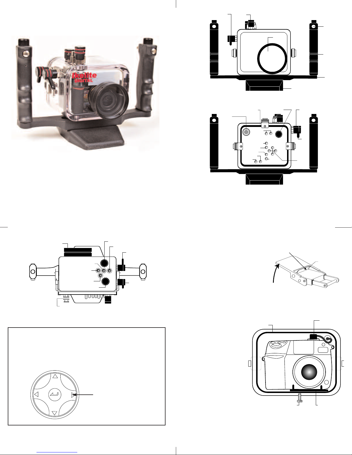
Ikelite Digital Housing
Lens Po r t
P
ower
FRONT VIEW
Lid
Snap
Quick Release
B
utton
Rubber
H
andles
Tray
Base
Multi
Selector
Shutter
Release
Delete
BACK VIEW
Display
Quick Review
Zoom
AF/AF
M
onitor
O'ring
Menu
Command
Dial
External TTL
Strobe Connector
S
hutter
Release
L
id
Snap
Lid
Snap
A
E/AF
Lock
TOP VIEW
External TTL
Strobe Connector
Lens Po r t
Power
AE/AF Lock
Exposure
Comp.
FUNC
LCD
Illuminator
Flash
Mode
Shutter
Release
Lift
Push For ward
Lid Snap Lock
Sync Cord &
Hot Shoe connector
O'Ring
Mounting
Bolt
Mounting
Tray
instruction manual
#6194.84 for Nikon Coolpix 8400
Congratulations on your purchase of an Ikelite Digital Camera
Housing. Ikelite has over 30 years of experience in the underwater
photographic and lighting market. Our products are designed and
built in the USA by Ikelite for both the professional and amateur
photographer.
The clear housing permits instant visual inspection of the camera
and all sealing surfaces as well as complete monitoring of controls
and camera LCD screens.
Ikelite Digital Housings are slightly negative in salt water for
stability. This housing has been water pressure tested at the
factory. Housing is pressure tested to 200’ (60m).
2
NNoottee:
:
There is no housing control for the center button on the
camera’s Multi Selector which is used to make a selection.
When the camera is in the housing and you have made a
change that requires pressing the center button, press the
Right Arrow button on the Multi Selector, it will make the
selection.
3
Depress to display sub-menu,
move cusor right,
or make Selection
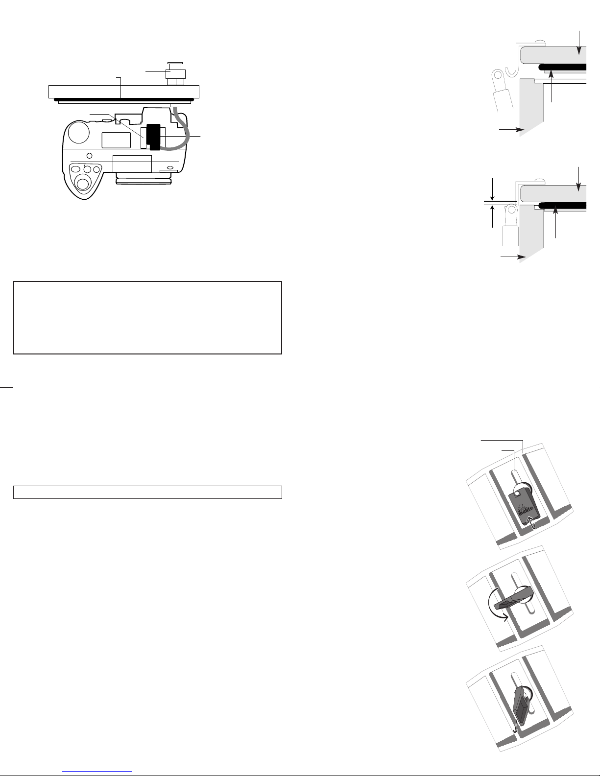
OOppeenniinngg tthhee HHoouussiinng
Lid Snaps have a
LLoocck
k
g
. To
open, push Lid Snap Lock
forward and lift as shown.
Keep pressure on the Lid Snap
so it does not fly open
quickly.
Some lid snaps have a
lot of spring tension once
they go over center, have a
firm grip on the lid snap.
IInnssttaalllliinngg tthhee CCaammeerra
a
Install a fully charged
battery
into the
camera before
securing the camera to
the housing’s mounting
tray.
Remove the back from
the housing. The
mounting tray for the
camera is secured to the
housing back. Position
the camera
on the tray
and secure it with the
mounting bolt which
threads into the
camera's tripod socket.
Before inserting the camera into the housing, pull out on the
housings AE/AF-L control so it does not obstruct installing the
camera in the housing.
4
Page 3
External Strobe
C
onnection/
Waterproof
C
ap
O
'ring
Housing Back
H
ousing Hot
S
hoe Connector
C
amera Hot Shoe
Camera
FFllaasshh CCoonnnneeccttiioon
Quick Release Base
Slot
Flip Quick Release
Lever Up
Rotate Quick
Release Lever
Remove Quick
Release Lever
and Base
n
When using an external strobe connect the housings Hot Shoe
Connector, slide the connector into the hot shoe of the camera
from the back as shown. Slide the connector forward until it
stops. This can be done after the camera is secured with the
mounting bolt.
NNOOTTEE:
:
The housing’s External TTL Strobe Connector’s waterproof cap
should only be removed when connecting an external strobe
with a sync cord. If no sync cord is connected to the housing
the connector’s waterproof cap must be in place before using
the housing in the water.
5
CClloossiinngg tthhee HHoouussiinng
1. Check to see that there is an o’ring
g
housing back
on the housing back and that it is
clean and in its proper location.
2.
Guide the back onto the housing.
ake care to see that the TTL sync
T
cord does not obstruct the
installation.
touch the housing
round. There should be an
a
even gap all the way around
etween the housing and the
b
The o’ring should
all the way
housing
housing back.
. Lift the lid snaps so they are
3
extended and place the lid snap
housing back
into the hook on the housing back.
4. To close the housing push
own on the lid snaps until
d
they snap into place. Lid
even gap
all 4 sides
snaps on opposite sides of
the housing should be closed
at the same time. Be sure they
are down far enough to engage
housing
the lock.
DDoouubbllee cchheecck
k
- Once the housing is closed, check the o’ring seal.
Check the gap between the housing back and the housing, it
should be even all the way around.
Look through the clear plastic back at the o’ring. You should
see a darkened area where the o’ring is compressed against the
housing back. If you do not see an even black compression seal
all the way around the back, open the lid snaps, reseat the housing
back and close the lid snaps. Visually check the seal again.
6
o’ring
o’ring
CChheecckkiinngg CCoonnttrroolls
s
Once the housing has been closed check to see that
the housing controls line up with the camera controls.
Turn the camera on and operate each of the housing controls
to get a feel for using the camera in the housing. Take a few
pictures with the camera in the housing.
CCAAUUTTIIOONN:
SShhuutttteerr RReelleeaasse
The camera's shutter release button operates in two stages.
e
:
When depressed halfway it activates the camera's exposure
meter and autofocus. When depressed fully it takes the picture.
This half stop of the shutter release is more easily felt when
using the camera out of the housing. But with some practice
you can feel the half stop when the camera is in the housing.
The camera's shutter release requires only minimal pressure to
activate. With the additional leverage of the housing’s shutter
release control you can put undue force on the camera's shutter
release button. This can result in damage to the camera.
Digital cameras have a noticeable lag time between when you
push the shutter release button and when the camera starts to
do something. It is human nature to push harder when the
camera
the camera
of the shutter release. It only requires a very light touch.
does not instantly respond. Take several pictures with
in the housing, paying special attention to the feel
QQuuiicckk--RReelleeaassee BBaassee,, HHaannddlleess aanndd TTrraay
QQuuiicckk--RReelleeaassee BBaasse
The Quick-Release Base is plastic.
A toggle lever located underneath
the base allows the base to be
easily removed from
Turn the housing upside down,
pull out on the toggle lever.
Rotate the lever 90° to remove
the base.
HHaannddlleess aanndd TTrraay
The handles on the housing are
rubber and the tray is aluminum.
Their weight helps to offset the
buoyancy of the housing. The
complete assembly is slightly
negative
control.
button
release for easily
attaching and removing strobe
arms. The tray and handles can
be removed from the housing.
To remove the
must be removed
to the nuts holding the tray on
the housing. Remove the 2 nuts,
washers and rubber spacers.
DDOO NNOOT
T
protruding through the housing.
e
the Tray.
y
underwater for better
The handles have a push
tray, the base
to gain access
remove the bolts
y
7
8
Page 4

LLuubbrriiccaanntts
1. Ikelite provides silicone lubricant with the housing.
We recommend that you use only Ikelite lubricant on Ikelite
products as some other brands may cause the o’ring to swell
and not seal properly.
. Use only enough lubricant to lightly cover control shafts
2
and o’rings. Wipe off any excess lubricant with a clean cloth.
L
Excessive lubricant can collect sand and dirt which may
interfere with proper sealing.
CCAAUUTTIIOON
NNeevveerr uussee sspprraayy lluubbrriiccaannttss aass tthhee pprrooppeellllaanntt iinnggrreeddiieenntt ccaan
ccaauussee tthhee ppllaassttiicc hhoouussiinngg ttoo ccrraacckk.
LLeennss PPoorrt
T
and gently dry the lens port to avoid water spotting. To clean
use a mild soap solution or lens cleaner.
Do not use alcohol or window cleaner on the Lens Port.
s
ubricant is not a sealant, it is used to reduce friction.
N
.
t
reat the glass in the lens port as a camera lens. After use, rinse
UUssiinngg FFllaassh
UUssiinngg tthhee CCaammeerraa’’ss BBuuiilltt--iinn FFllaasshh.
If you do not have an external flash the camera’s built-in flash
can be used to illuminate subjects underwater. The housing has a
built-in Diffuser to aid in providing even illumination.
EExxtteerrnnaall SSuubbssttrroobbees
External strobes offer several advantages over using the
camera’s built-in flash. External strobes move the flash away
rom the camera lens which helps reduce backscatter. They also
f
n
expand lighting options to achieve the best lighting for
ifferent subjects and lenses. A strobe such as the DS51 is ideal
d
for use with macro and most standard camera lenses up to
28mm. When an optional wide angle lens is added a strobe such
as the DS125 is needed as it has a greater angle-of-coverage. A
econd external strobe can be added to fill the shadows and
s
produce more realistic photographs.
UUssiinngg aann EExxtteerrnnaall FFllaasshh wwiitthh SSyynncc CCoorrdd.
This camera and housing can use any Ikelite Substrobe, in the
Manual Mode when connected with a #4103.51 sync cord.
Substrobe 50
Substrobe DS50
Substrobe DS51
Substrobe 100A
Substrobe DS125
Substrobe 200
Strobes do not work TTL with this housing.
h
.
s
.
9
UUssiinngg aann EExxtteerrnnaall FFllaasshh wwiitthh tthhee EEVV--CCoonnttrroolllleer
This camera and housing can utilize the Ikelite EV-Controller with
any Ikelite DS Substrobe. The EV-Controller provides 10 manual
power settings in 1/2 stop increments when used with an Ikelite
DS Substrobe.
UUssiinngg tthhee EEVV--CCoonnttrroolllleerr wwiitth
SSyynncc CCoorrdd ##44110033..551
The EV-Controller has a
bulkhead and can be
connected directly to the
housing with sync cord
#4103.51 eliminating the
need to use the camera’s
built-in flash.
CCaammeerraa MMeennuu sseettttiinnggs
wwhheenn uussiinngg tthhe
EEVV--CCoonnttrroolllleerr wwiitth
aa ssyynncc ccoorrdd.
Go to Speedlight
Options, Pop Up set to
Auto, Speedlight Control
set to Internal Off.
e
.
h
1
s
h
r
10
UUssiinngg FFllaasshh CCoonntt.
UUssiinngg tthhee EEVV--CCoonnttrroolllleerr iinn SSllaavvee MMoodde
A flash Deflector is provided
with the housing.
When using an external flash
with the EV-Controller in the
slave mode the Deflector is
used to redirect the camera’s
flash to the sensor in the EVController which triggers the
DS Substrobe.
IInnssttaalllliinngg DDeefflleeccttoor
To install the Deflector
spread the port clamp at the
spring end and slide over the
lens port. The white plastic
should be placed in front of
the camera flash. The port clamp should be pushed back against
the front of the housing.
UUssiinngg DDuuaall SSuubbssttrroobbees
For dual strobes the #4103.52 dual sync cord can be used or the
second strobe can be slaved using the Ikelite Remote TTL Slave
#4100.5.
NNOOTTEE:
:
Ikelite Substrobes manufactured before June 1, 2001 require a
modification to be used in a two strobe set-up with a dual sync cord.
.
e
This edge
against housing
Port Clamp
r
Spread to Install
Deflector
material
Spring
s
11
12
Page 5

OOppttiioonnaall AAcccceessssoorriiees
BBaacckk OO''rriinngg ##11009
'rings last for several years if properly maintained.
O
(See Maintenance) Always carry a spare o'ring in case
the housing o'ring becomes damaged or lost.
UURR//PPrr00 FFiilltteerr ##66444411..441
s
9
1
13
MMaaiinntteennaanncce
he Ikelite Digital Housing should be given the same care and
T
attention as your other photographic equipment. In addition to
ormal maintenance we recommend that the housing be returned
n
to Ikelite periodically to be checked and pressure tested.
DDoo NNoot
.
1
for prolonged periods. Heat may damage the camera.
DDoo NNoot
2.
3. Before using the housing, always check the tightness
of the
heck each
C
to make sure they are tight. There is a slight chance
hat either could vibrate loose during travel.
t
4.
Keep the back o’ring clean and lightly lubricated. To lubricate remove
the o’ring from the back. Put a small amount of lkelite lubricant on
your fingers. Draw the o’ring through your fingers to apply a light
coating of lubricant. Only apply enough lubricant to make the o’ring
feel slick.
will help to keep the o’ring from drying out and will help to show
a dark sealing line when the housing back is properly sealed.
5. Keep the area where the o’ring fits and the sealing surface
of the housing clean.
6. Rinse the housing exterior thoroughly in fresh water after each
salt water use. Dry with a soft cloth. Dry lens port to eliminate
water spotting.
After several uses in salt water soak the housing in a mild soap
solution, rinse and dry before storage. When storing the housing,
remove the back o’ring, lightly lubricate and place in a plastic bag.
Place the plastic bag with o’ring inside the housing for safe keeping.
CCAAUUTTIIOON
e
t
eave the camera and housing in direct sunlight
l
t
ship the camera in the housing.
sseett ssccrreew
w
in each control knob. (See page 17)
ccoonnttrrooll ggllaannd
DDoo NNoott ssttrreettcchh tthhee oo’’rriinng
d
enetrating the housing
p
g
. This light coating of lubricant
N
NNeevveerr uussee sspprraayy lluubbrriiccaannttss aass tthhee pprrooppeellllaanntt iinnggrreeddiieenntt ccaann ccaauussee tthhe
ppllaassttiicc hhoouussiinngg ttoo ccrraacckk.
.
14
e
CCoonnttrrooll MMaaiinntteennaanncce
Ikelite controls are designed to provide years of reliable service
with minimal maintenance.
1. Push button controls require no maintenance other than rinsing
in fresh water after saltwater use. If a push button control
becomes difficult to push or if it sticks when depressed, soak
the housing in lukewarm fresh water. After a few minutes
operate the push button. If this does not correct the problem,
return the housing to Ikelite for maintenance.
2. Some of the controls have long shafts. These controls can be
pulled out, exposing the shaft (see drawing).
3. Some of the controls have a short shaft and cannot be pulled
out exposing the shaft for lubrication. In the unlikely event one
of these controls sticks or becomes difficult to operate you can
remove the control from the housing and lubricate it, or return
the housing to Ikelite for maintenance. To remove the control,
loosen the set screw in the knob (allen wrench required); remove
the knob. If there is salt or dirt build-up on the exposed control
shaft, clean the shaft. Open the housing and gently slide the
control shaft out of the control gland. Clean and lightly lubricate
the shaft, including the end of the shaft. Slide the shaft back into
the control gland and gently slide it back and forth a few times
without fully removing the shaft from the gland. Replace the
knob, NOTE the flat area on the shaft, the set screw in the knob
should tighten down against the flat area on the control so the
knob does not turn on the shaft.
e
lubricate shaft
housing
pull out to
expose shaft
To lubricate the control, gently pull on the knob until the
stainless steel shaft is exposed. Lightly lubricate the shaft, then
move the shaft in and out several times. This will lubricate the
x’ring in the Ikelite control gland. This should be done before
using the housing after a prolonged storage period, or once a
week when the housing is in use.
contr
shaft
Tighten set scr
against this ar
replacing the knob.
ol
ew down
ea when
housing
Flat
Lubricate end of shaft
before reinserting into gland
gland
Loosen set screw
(allen wr
ench r
equir
ed)
15
16
Page 6

PPhhoottoo TTiipps
1. The number one rule in underwater photography is
eliminate as much water between camera and subject as
possible. Get as close as you can to the subject, then use the
zoom. If you are using flash, subjects beyond 6 feet (1.8m)
w
2. Digital cameras have a slight lag time between when you
press the shutter release button and the camera actually takes
the picture. Hold the camera steady a second or two after
p
3. Do not shoot down on subjects as they will quite often blend
nto the background and be difficult to see in the photograph.
i
Shoot subjects straight on or shoot up at a slight angle using
the blue water as a contrasting background.
4. Underwater flash is used to restore the warmer colors
iltered out by the water as well as to illuminate the subject.
f
When photographing underwater, set the camera to use flash
on every shot.
s
ill not have much color.
ressing the shutter release button.
GGeenneerraall TTiipps
1. Due to the power required to operate the camera, flash,
and LCD screen it is a good idea to start each dive with a
fresh set of batteries. Use NiMH or LITHIUM-ion batteries
(see camera manual).
2. As soon as you enter the water, take a moment and check the
housing to see that it is properly sealed.
3. Next, check to see if there are any bubbles on the face
of the lens port. If there are, take your finger and remove them.
If there are bubbles on the lens port they can produce soft focus
spots in your photographs.
4. Due to the light sensitivity of digital cameras they may
overexpose close-up photographs when using an external flash.
If close-up photos are constantly overexposed, use the camera
menu and change the external strobe exposure to -1 or higher.
hoot a few test photographs, changing the strobe exposure
S
compensation until you are satisfied with the results.
5. Shoot with the smallest aperture possible when shooting
close-up with flash.
6. Use the macro mode for close-up photographs.
7. Shoot pictures at the highest resolution. Several printing
methods require high resolution. It is easy to reduce the size
and resolution, but almost impossible to increase size and
resolution from a small file and obtain a satisfactory result.
s
17
IIkkeelliittee LLiimmiitteedd WWaarrrraanntty
All Ikelite products are warranted against any manufacturing
defects for a period of one (1) year from the date of purchase.
Defective products should be returned prepaid to Ikelite.
Ikelite will, at its discretion, repair or replace such products,
and will return to customer prepaid. All other claims, of any
nature, including but not limited to bulb failure are not covered.
Except as mentioned above, no other warranty expressed
or implied, applies to this Ikelite product.
RReettuurrnniinngg PPrroodduuccttss ffoorr SSeerrvviicce
Ikelite is most interested in performing any service to assure
that all products perform as intended. For repair or service, return
the product to the address below with your name, address, phone
number and a brief description of the problem. Evidence of
purchase date must be provided to obtain warranty service.
IIkkeelliittee UUnnddeerrwwaatteerr SSyysstteemms
IInnddiiaannaappoolliiss,, IINN 4466220088 UUSSA
y
e
5500 WW 3333rrdd SSttrreeeet
s
t
A
18
331177--992233--4455223
eemmaaiill:: iikkeelliittee@@iikkeelliittee..ccoom
wwwwww..iikkeelliittee..ccoom
3
m
m
DDiiggiittaall 66119944..8844--vv0011--0022005
5
Page 7

##
 Loading...