

Page 1
AF35 AutoFlash
Instruction Manual
4035 - 4035.1
35
AF
ikelite
AUTOFLASH
ikelite
Thank you for your purchase of Ikelite equipment. Please read this
instruction manual completely before attempting to operate or dive
with this product. Please refer to the back page of this manual to
register your Ikelite product.
Page 2
Table of Contents
Housing Compatibility ................................................P. 3
ncluded with AF35 AutoFlash Kit ............................P. 3
I
Parts of the AF35 ........................................................P. 4
Specifications ..............................................................P. 5
Battery Compartment ..................................................P. 4
Opening - Battery Compartment O-ring ..........................P. 5
Changing the Batteries - Closing the Compartment ......P. 5
AF35 Flash Settings (Off, Auto, Manual) ........................P. 6
AF35 Flash Ready Light..................................................P. 7
Ready Light in Auto Mode ..............................................P. 7
Setting the Auto Exposure Selector Dial ..................P. 8
AF35 Flash Diffuser ....................................................P. 9
Mounting Ikelite Housing to the Tray ........................P. 10
Tray Inserts......................................................................P. 11
Sony Housing Tray Insert Installation..............................P. 12
Mounting Housing to the Tray ........................................P. 13
Installing Housing Deflectors ....................................P. 14
Connecting AF35 Handle to Tray (Single or Dual)........P. 16
Flex Arm ......................................................................P. 17
Lubricant ......................................................................P. 18
Maintenance ................................................................P. 18
Routine Cleaning - Long Term Storage ..........................P. 18
Battery Compartment Flooding ................................P. 19
Troubleshooting ..........................................................P. 20
Recommendations ......................................................P. 21
Pro-V8 LED Lite ..........................................................P. 21
2
Page 3

Table of Contents
Technical Support ......................................................P. 22
Limited Warranty ........................................................P. 23
Returning Products for Service ................................P. 23
Product Registration ..................................................Back Cover
- continued
Housing Compatibility
The AF35 AutoFlash fits Ikelite ULTRAcompact and Compact
digital housing styles DC100 and DC200, and most compact
digital housings manufactured by Canon, Olympus, Panasonic,
and Sony.
Included with AF35 AutoFlash Kit
- AF35 AutoFlash
- Flash Diffuser
- Flexible Arm
- AutoFlash Sensor
- Rubber Grip
- Tray (single or dual)
- Tray Inserts
- Mounting Hardware
3
Page 4

Parts of the AF35
35
AF
ikelite
AUTOFLASH
ikelite
Selector
Dial
AF35 AutoFlash
Pop-bead
Flex Arm
Sensor
Rubber Grip
Tray
Specifications
Firing Modes ............................Auto - 6 manual power settings
Energy Rating ..........................35 watt-seconds
Coverage Angle ........................70° - 80° with diffuser
Guide # (ISO 100) feet..............28 surface - 16 underwater
Guide # (ISO 100) meters ........9 surface - 5 underwater
Color Temperature ....................5700° K
Power Source............................4 “AA” alkaline, NiCad, NiMH
Flashes......................................300 full power
Recycle Time ............................2.5 seconds
Weight ......................................0.6 kg - 1.3 pounds
Depth Rating ............................90m - 300 feet
CE - Compliant with applicable EU directives.
Complies with FCC part 15, subpart B, Section 15.109 for Class “B”
Products.
4
Page 5
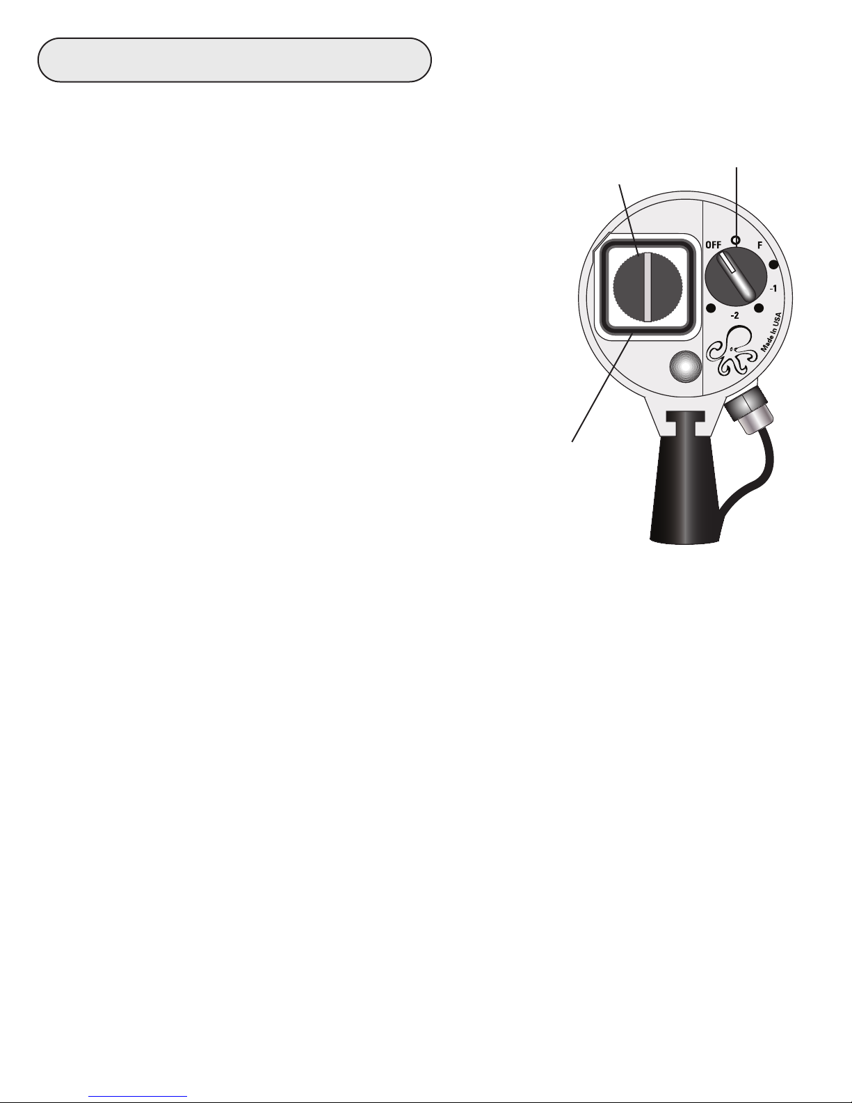
Battery Compartment
Opening - Always turn the AutoFlash OFF (as shown) and dry the flash
before opening the battery door. To access the
Mode Switch
battery compartment, rotate the knob
counter-clockwise several turns and gently
Knob
remove the door. Tilt the back of the flash down
AUTO
while removing the battery door to eliminate the
possibility of water droplets falling into the
battery compartment. Note: Do not remove the
knob from the battery door.
Battery Compartment O-ring
Keep the o-ring and sealing surfaces
clean. Lightly lubricate the exposed
portion of the o-ring with the Ikelite
O-ring seal appears
as solid black line
when properly sealed
silicone lubricant provided.
Changing the Batteries
Install four AA-cell batteries: alkaline, NiCad, or NiMH. Refer to the “+”
and “-” markings in the battery compartment to help properly install the
batteries. If the batteries are installed incorrectly it may damage the
electronics. Batteries should be replaced when the flash takes 15
seconds or longer to recycle.
Closing the Compartment
Check that the o-ring and sealing surfaces are clean, the o-ring is lightly
lubricated and in its original position. Replace the battery door. Make
sure it fits into the recess around the battery compartment. Rotate the
knob clockwise several times and firmly hand-tighten to assure the
proper o-ring seal, otherwise the battery compartment may leak.
Caution: Do Not use a tool when tightening as it may damage the
battery door.
Visually confirm that there is a solid black line which indicates a
seal all the way around the door.
The o-ring seal is visible through the battery door.
5
Page 6
AUTO
AUTO
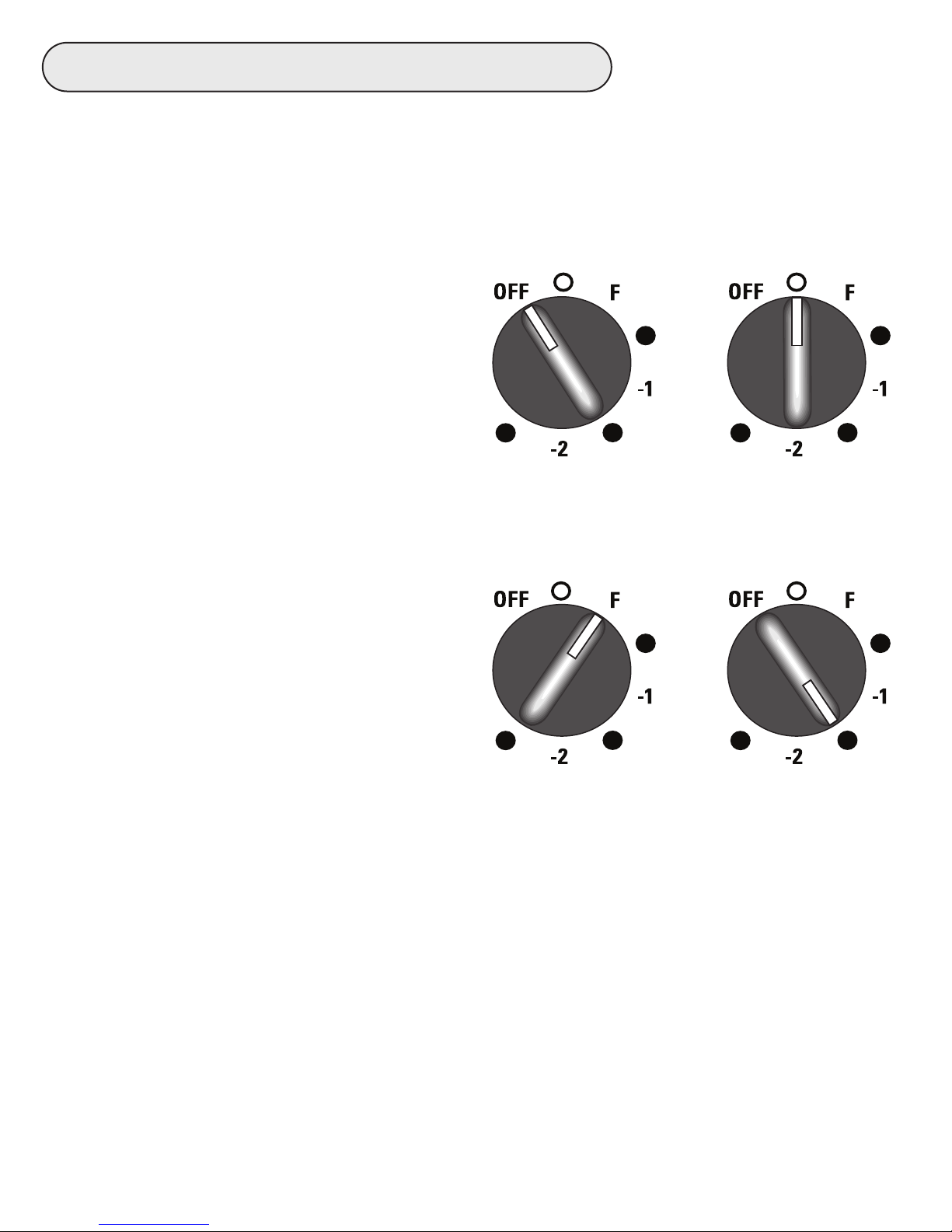
AF35 Flash Settings
To use the AF35 AutoFlash in the Auto or Manual Mode the camera’s
built-in flash must be set to fire on every shot as it is used to trigger the
AF35 AutoFlash.
OFF - Figure 1 shows the AF35
flash Mode Switch set to OFF.
Always turn the flash OFF when not
in use for prolonged periods or when
changing batteries.
AUTO - Figure 2 shows the AF35
flash Mode Switch set to AUTO.
From the OFF position rotate the
(Fig.1) (Fig.2)
mode switch clockwise to access the
AUTO exposure setting; the white
indicator on the knob aligns with
AUTO. When taking pictures with
the Mode Switch in the Auto
position, the Auto Sensor
automatically controls the flash
output of the AF35 flash.
See Auto Exposure Selector Dial,
AUTO
(Fig.3) (Fig.4)
page 8, for setup and additional
information when using the AF35 in the AUTO mode.
MANUAL - Figure 3 shows the Mode Switch in the manual exposure
mode with the AF35 turned to the F (full power) position. Rotate the
Mode Switch clockwise to access the different power settings. Each
AUTO
power setting clockwise from F reduces the light output of the AF35 in
one-half f-stop increments. When shooting in manual mode, it is
suggested that you start at F (full power). If the subject in the photo is
underexposed (too dark) you must move closer to the subject.
6
Page 7

AF35 Flash Settings - continued
If the subject is overexposed (too light), then you can rotate the mode
switch clockwise to reduce the light output of the flash until the desired
exposure is obtained. The AF35 provides five reductions in power in 1/2
f-stop increments from the full power setting. Figure 4, page 6, for
example, shows the Mode Switch set to minus 1-1/2 f-stops. When the
AF35 is in any manual setting the Auto Exposure Selector Dial setting
has no effect on the flash output.
Switch the AF35 between Auto and Manual settings at any time.
AF35 Flash Ready Light
The AF35 flash features a ready/confidence light at the rear of the flash
that glows when the flash has recycled and is
ready to fire. When the recycle times range
AUTO
between 10 and 15 seconds it is recommended
that fresh batteries be installed.
Note: The AF35 flash will most likely recycle
faster than the camera’s built-in flash. Since
the camera’s built-in flash is required to trigger
the AF35 flash, make sure the camera’s built-in
flash has recycled and is ready to fire before
Ready
Light
taking a picture.
Ready Light in Auto Mode
When the AF35 fires in the Auto Mode and enough light reaches the
subject for proper exposure the ready light will glow green for about 2-3
seconds, then glow red. If the ready light does not glow green, but glows
red immediately after taking a picture, not enough light reached the
subject for proper exposure. Move closer to the subject and take another
picture and check the ready light.
7
Page 8

Setting the Auto Exposure Selector Dial
On the side of the Auto Sensor is the Auto
Exposure Selector Dial. Different cameras
may require different exposure values. Once
the correct exposure value is determined for
a particular camera, no further adjustments
Ikelite
10
3
2
4
1
5
9
7
6
8
MADE IN THE USA
should be necessary to obtain acceptable
flash exposures of varying subjects
Auto Exposure
Selector Dial
within normal shooting ranges.
To determine the camera’s optimum Exposure Value we recommend the
following procedure. This procedure can be done above water.
Make sure the camera’s battery is fully charged and the AF35 flash has
fresh batteries. Assemble the AF35 flash and camera housing with the
flash deflector installed on the housing. Make sure the camera’s built-in
flash is set to fire on every shot and is fully charged. Turn the AF35 Mode
Dial to AUTO. Set the Auto Exposure Selector Dial to 5 as shown above.
Position the camera and flash approximately 1m (3 feet) from a colorful
subject. Subject should not be all white or black. Take a picture, review
the picture, if the picture is overexposed (light), turn the Auto Exposure
Selector Dial down to 4, if the picture is underexposed (dark) turn the Auto
Exposure Selector Dial up to 6. Repeat this procedure until the optimum
exposure is obtained. Once the optimum Auto Exposure Value has been
determined for that camera, use that value anytime that camera is used
with the AF35 in the Auto Mode. Repeat this procedure anytime a different
camera is used with the AF35 AutoFlash.
For advanced users, the Auto Exposure Selector Dial can be used for
exposure compensation while remaining in the automatic mode. When the
AF35 is set in the Auto Mode, the Auto Exposure Selector Dial can be
used to increase or decrease the flash intensity in difficult lighting
conditions.
8
Page 9

Setting the Auto Exposure Selector Dial - continued
Using Dual AF35 AutoFlashes
When using dual AF35 AutoFlashes, determine the optimum Auto
Exposure Value for one AF35 AutoFlash as described on page 6, then set
the same Auto Exposure Value on the second AF35 selector dial.
AF35 Flash Diffuser
The flash diffuser adds 10° to the angle-of-coverage of the flash. The
diffuser is usually not required unless a wide angle lens is being used.
The white diffuser features two protruding tabs for use in installation and
removal. The tabs on the diffuser should be positioned away from the
flash.
Place the diffuser over the front of the flash. Spread the two tabs apart,
insert the diffuser into the
recessed front, and then
rotate the diffuser until it
locks into position.
To remove the diffuser, bend
one tab out towards the
edge while lifting
simultaneously.
A lanyard can be attached to
the diffuser by threading it
through the two holes.
Tab
Push and Lift
to Remove
Holes for Lanyard
Tab
9
Page 10

Mounting Ikelite Housing to the Tray
Applies to Single or Dual Tray.
The AF35 AutoFlash can ONLY be mounted to Ikelite ULTRAcompact
and Compact Digital housing models DC-100 and DC-200.
Turn the housing so the tray mounting inserts on the bottom of the
housing are facing up. Place the tray across the bottom of the housing
and align the two outer holes in the tray with the mounting inserts in the
bottom of the housing. Insert the two mounting bolts as shown below
and tighten the bolts firmly to secure the tray to the housing.
Note: Your mounting hardware includes 2 12-24 thread and 2 1/4-20
thread size screws. Make sure you use the correct thread size screws
with your housing. Do Not cross-thread the Mounting Inserts.
Single Tray
Mounting Insert
Mounting Bolts
10
Ikelite DC-100 UltraCompact Housing
Page 11

Tray Inserts for (Canon, Olympus, Panasonic, Sony & Universal)
Applies to Single or Dual Tray.
Non-Ikelite
CANON B
housings are
CANON A
mounted to the
OLYMPUS
tray with a single
bolt. To keep the
CANON C
camera housing
from rotating on
the tray, a Tray
Universal Rubber Insert
SONY A
PANASONIC
Insert must be
installed. Note that there are 5 Tray Inserts included with the AF35 Tray.
Select the Tray Insert for the corresponding camera housing being
installed. If one of the plastic inserts is not compatible, use the rubber
universal insert which will help prevent the housing from rotating when
tightened to the tray. For Sony Insert installation see Page 12.
Installation
SONY B
1. The Tray Inserts have an adhesive coating on one side. Once the correct
insert is selected, remove the protective backing to expose the adhesive.
2. Align the Tray Insert with the Tray Recess, the arrows on the Tray Insert
should be pointing toward the holes in the tray.
3. Place Insert into Recess and push down to secure Insert to tray.
CANON B
Protective
Backing
CANON B
Tray Insert
CANON B
Insert
Installation
Diagram
Tray Insert
Tray Recess
Mou
nting H
CANON A
CANON A
oles
CANON A
11
Page 12

Sony Housing Tray Insert Installation
Applies to Single or Dual Tray.
Sony housings have 2 different size Base Plates. The Tray Insert
marked Sony has 2 different cut-outs. To determine the correct cut-out,
place each of the Sony Tray Insert cut-outs against the Sony housing
Base Plate as shown below. Use the cut-out that fits snug around the
Base Plate. When the correct cut-out is determined proceed with the
installation.
Base Plate
SONY A
SONY B
Tripod Mount
Tray Insert
See the “Insert Installation Diagram” on page 11 for the following
procedure:
1. The Tray Insert has an adhesive coating on the side opposite the
lettering. Remove the protective backing to expose the adhesive.
2. Align the Tray Insert with the Tray Recess, the arrows on the Tray Insert
should be pointing toward the holes in the tray.
3. Place Insert into Recess and push down to secure Insert to tray.
4. Continue to page 13 for mounting the housing to the tray.
12
Page 13

Mounting Housing to the Tray (Canon, Olympus, Panasonic &
Sony Housings)
Applies to Single or Dual Tray.
After the proper Tray Insert is installed, the housing can be mounted to
the AF35 tray. Turn the housing so the Tripod Mount on the bottom of
the housing is facing up. Place the tray across the bottom of the
housing. A lign the center hole in the tray with the hole in the Tripod
Mount on the bottom of the housing. Insert the mounting bolt with lock
washer as shown below and tighten the bolt firmly to secure the tray to
the housing. Check that the Tripod Mount aligns correctly with the Tray
Insert restricting the housing from rotating on the tray.
Single Tray
Tripod Mount
Mounting Bolt
Lock Washer
Tray Insert
13
Page 14

Installing Housing Deflectors
Installing a Deflector in front of the camera’s built-in flash will block the
camera’s flash from going forward and lighting the particles in the water;
helping to reduce backscatter, it will also deflect the light back toward
the AF35 Sensor used to trigger the AF35 Flash.
Ikelite Housings
Deflectors are supplied with Ikelite housings, see housing instructions for
installation.
Non-Ikelite Housing Deflector Installation
Most Canon, Olympus and Sony digital camera housings have a flash
diffuser built on the housing to which the deflector can be attached, see
drawing, page 15. If the housing does not have a flash diffuser pick a
spot on the outside of the housing in front of the camera’s built-in flash
to mount the deflector.
Deflector Kit includes:
1 strip of hook material, 1/4” wide x 6” long
1 strip of loop material, 2” wide x 3” long
1. The loop material (deflector) is white on one side and black on the other
side. The white side will go against the housing as it has loops that will
stick to the hook material once it is secured to the housing.
2. Using a piece of paper, cut a template to fit on the outside of the housing
in front of the camera’s built-in flash. Trace the template on the loop
material and cut it out. Test fit the loop material (deflector) on the housing
and trim as necessary.
14
Page 15

Non-Ikelite Housing Deflector Installation - continued
3. Position the loop material (deflector) on the housing to determine where to
locate the 2 strips of hook material to secure the deflector to the housing.
Cut 2 strips of the hook material to fit on each side or on the top and
bottom of the deflector. Peel the adhesive backing from the hook material
strips and press them onto the housing. The loop material (deflector) can
now be secured or easily removed from the housing.
Flash
Diffuser
Port
Deflector Hook Material
Deflector Material
Cut-out
Cut-out Defector
Material
Non-Ikelite Housing Front
Port
Non-Ikelite Housing Front
Port
Non-Ikelite Housing Front
15
Page 16

Connecting AF35 Handle to Tray
(single or dual )
The base of the Handle Mount that slides over the Tray Mount has a
nylon screw. Note that the tray has a notch for the nylon screw to fit into
when the handle is mounted to the tray and the nylon screw is screwed
down. Back the screw out far enough to slide the handle base onto the
tray mount. Align the handle mount with the tray mount as shown, push
the handle mount onto the tray mount and secure with nylon screw.
Reverse this procedure to remove the handle.
Tray Mount
Nylon Screw
Handle Mount
Secure Handle to Tray
with Nylon Screw
Locking Groove
16
Page 17

Flex Arm
The AF35 Flex Arm is quite versatile, it allows the flash head to be
placed in many different positions for optimal lighting. The flash head is
connected to the sensor with a sync cord that runs through the center of
the Flex Arm. If the flex arm is bent too far it may separate from the top
bead on the sensor body. The Flex Arm and flash will still be connected
to the sensor and handle by the sync cord, DO NOT put undue force on
the sync cord. If the Flex Arm separates from the top of the sensor,
position the bottom bead of the Flex Arm over the bead on the top of the
sensor body and push down to reinstall, Figure 1. The flex arm should
snap back into position, Figure 2.
Your AF35 Flex Arm utilizes a pop-bead system which allows easy
repositioning of the strobe while underwater. After extended use, the
pop-beads will loosen slightly and may no longer hold the strobe in a
fixed position above water. This should not be a problem underwater.
35
AF
ikelite
AUTOFLASH
ikelite
Align arm pop-beads
and push down on
sensor base to rejoin
Figure 1
Figure 2
35
AF
ikelite
AUTOFLASH
ikelite
17
Page 18

Lubricant
- Use only Ikelite brand silicone lubricant with Ikelite brand o-rings; other
brand lubricants can cause the Ikelite o-rings to swell in size.
- Do Not use spray lubricant; it can crack the plastic parts of the kit.
- Lubricant reduces friction and prolongs the life of o-rings, it is not a
sealant. Use only enough lubricant to lightly cover the area being
applied; wipe off any excess with a clean cloth.
Maintenance
Your Ikelite AF35 AutoFlash Kit should be given the same care and
attention as your other photographic equipment.
Routine Cleaning
Caution: Make sure the AF35 battery door is on and tightened down
before exposing the flash to water. Ideally, water should never enter the
battery compartment. If this does occur, see “Battery Compartment
Flooding” on page 19.
1. Always rinse the exterior of the AF35 with fresh water after use,
especially after exposure to salt water. While rinsing, turn the mode
switch to free salt or debris that might have accumulated in recesses
during the dive.
2. Dry the AF35 thoroughly.
Long Term Storage
- Make sure the battery door is on and tightened down firmly.
- Soak the Kit in a mild soap solution, operate the mode switch to free salt
or debris, rinse and dry before storage.
-When storing the Kit, remove the batteries from the flash. Lightly
lubricate the exposed part of the door’s o-ring and store the AF35
with the battery door lightly screwed on, this will allow any hydrogen/air
mixture to escape the battery compartment and avoid unnecessary
pressure on the o-ring that could cause it to flatten.
18
Page 19

Battery Compartment Flooding
The battery compartment is separate from the AF35 factory sealed
electronics. Should the battery compartment flood, remove the batteries,
flush the compartment with fresh water and dry thoroughly. Determine
the cause of the flooding to the best of your ability. Send the AF35 kit to
Ikelite for inspection and testing as soon as possible.
Often, divers find themselves in remote locations for extended periods
without access to multiple flashes. If the flash with the flooded battery
compartment is the only one available to you at the time and you’re
desperate to continue shooting, please follow these instructions for a
temporary fix:
1. Open the battery compartment, remove batteries and water. Blow out
as much water as possible with a blow dryer or air from a scuba tank.
2. Wash out the battery compartment with alcohol. Blow dry the battery
compartment again with a blow dryer or air from a scuba tank.
3. Caution: Replace all batteries after battery compartment flooding. Never
re-use batteries that have been wet. The water could cause an internal
short circuit in the flash at some later date, potentially causing an
explosion.
4. Reassemble the AF35 with fresh batteries.
5. After returning from your trip, send the AF35 Kit to Ikelite for inspection
and testing.
19
Page 20

Troubleshooting
Problem
Strobe will not Fire
Solution
-
Check the AF35 Ready Light. Turn the Flash
Mode Switch to OFF and then back to AUTO.
Make sure the switch has actually clicked into
position.
- Check that the batteries are inserted according to
the “+” and “-” markings. Note: it is possible to buy
bad “new” batteries; check the voltage output with
a meter. If using rechargeable batteries make sure
the charger is working properly and that the
batteries are fully charged.
Check that the camera’s built-in flash is turned on
-
and is set to fire on every shot.
20
Page 21

Recommendations
- Take the time to examine the entire assembly setup above water. An
improper seal can cause a lot of damage. Always check for leaks once
you place the equipment in the water.
- Photograph through as little water as possible; move in close. Maximum
recommended shooting distance for good lighting is 1.8m (6’).
- Use the AF35 diffuser for softer lighting or wider coverage.
- Always carry spare batteries. Weak batteries are the cause of many
flash and camera problems; check the voltage with a meter. Note: it’s
possible to buy bad “new” batteries.
- The AF35 has a flexible arm for positioning the flash. Check that the
flash is aimed at the subject being photographed.
- When taking pictures in rapid succession, note that the AF35 flash will
recycle much faster than the camera’s built-in flash. Since the camera’s
built-in flash is used to trigger the AF35 you must wait for the camera’s
built-in flash to recycle.
- Make sure the flash deflector is installed in front of the camera’s built-in
flash. This not only helps direct light to the sensor but also aids in
reducing backscatter in photographs.
Pro-V8 LED Lite
The Pro-V8 LED Lite is an easy and affordable way to add light for shooting
video and night diving. See website for details and mounting options:
www.ikelite.com.
21
Page 22

Technical Support
Please read the troubleshooting section of this instruction manual before
contacting Ikelite Technical Support.
Email: ikelite@ikelite.com
Phone 317-923-4523
Fax 317-924-7988
22
Page 23

Limited Warranty
The AF35 AutoFlash is warranted against any manufacturing defects for
a period of two (2) years from the original date of purchase. Defective
products should be returned to Ikelite postage paid. Ikelite will, at its sole
discretion, repair or replace such products, and will return to customer
postage paid. All other claims of any nature are not covered. Except as
mentioned above, no other warranty expressed or implied applies to this
Ikelite product.
Returning Products For Service
Ikelite is most interested in performing any service to ensure that all
products perform as intended. Evidence of purchase date must be
provided to obtain warranty service.
No prior authorization is required. You may return directly to us or
through your dealer. Please include a brief description of the problem,
any relevant email correspondence, and/or instructions on what you
want us to do. Always include name, shipping address, email address,
and phone number inside of the package. Send postage paid to:
Ikelite Underwater Systems
Attention: Service Department
50 West 33 Street
Indianapolis, IN 46208 USA
No reimbursements for postage paid will be issued.
You may also want to insure the package.
Returning Products for Service (outside the United States)
For the separate international customs documentation form that you
complete to accompany the shipment, please state or designate that the
enclosed products were originally manufactured in the USA and are
being returned to the manufacturer for repair service. Value of the
equipment listed for customs purposes should be zero.
23
Page 24

Product Registration
Please go to www.ikelite.com to register your Ikelite housing within 15
days of purchase.
Ikelite Underwater Systems
50 West 33rd Street
Indianapolis, IN 46208 USA
www.ikelite.com
4035_4035.1_AF35_AutoFlash_06-1012
 Loading...