

Page 1
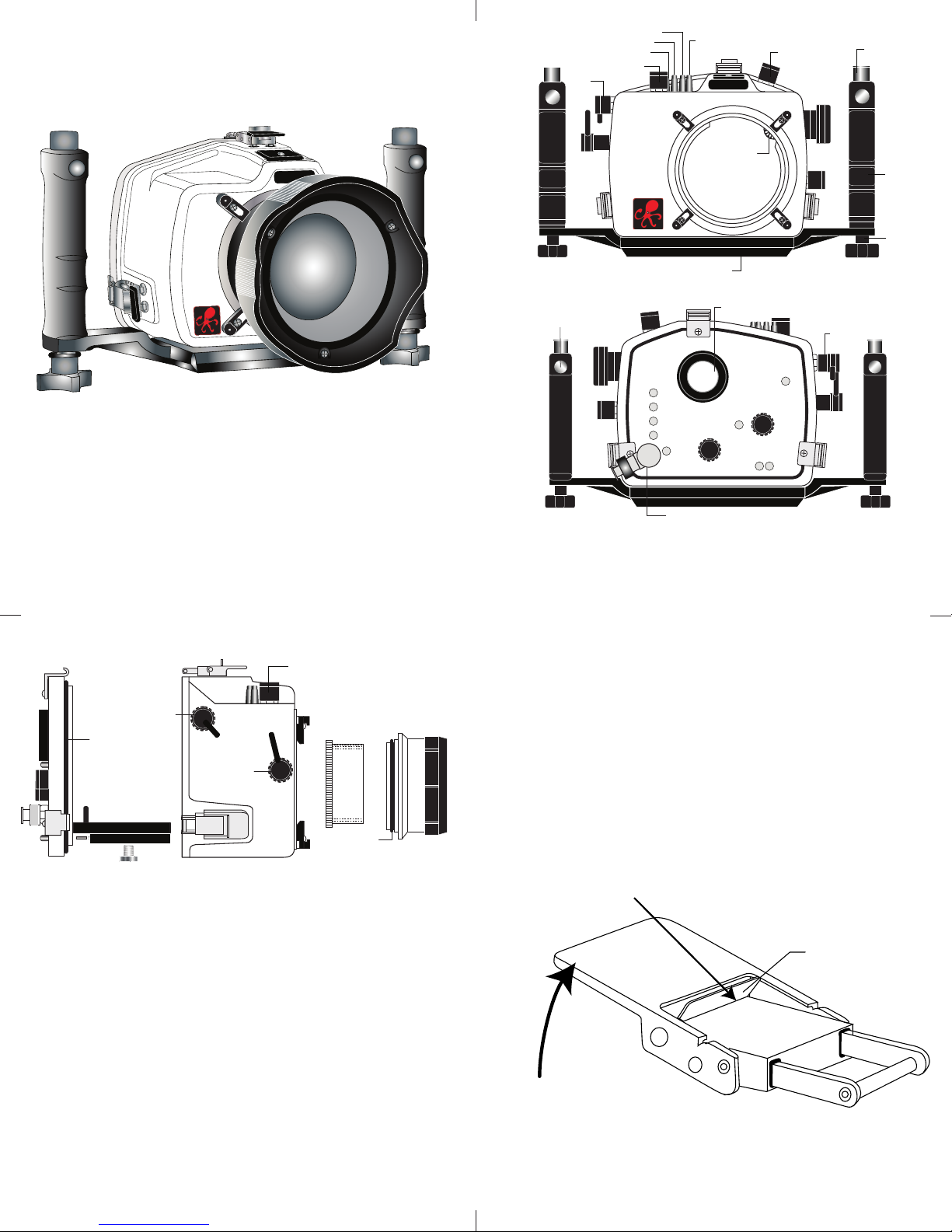
Strobe
Mount
Rubber
Handle
Quick-Release
Strobe
Mount
Gear Sleeve
Drive Gear
Zoom
Control
Lid Snap
Mode
Dial
Lens
Release
Main Dial
Meter/Flash
Drive Mode
AF/WB Mode
I
lluminator
Lid
Snap
Shutter
Release
AE/FL
L
ock
Port Lock
A
luminum Tray
Port
Opening
IKELITE
Quick
Release
Button
External Strobe Connector
and Waterproof Cap
Viewfinder Port
Shutter
Release
[D] Playback
[E] Erase
[F] ON/Off
[G] Set
[H] Quick Control
[I] AF Point
A
B
C
D
E
F
G
H
J
I
Lens
Release
Zoom
AE/FE Lock
[A] Menu
[B] Info
[C] Jump
[J] eTTL Mode/Compensation
Gear
Sleeve
Port
O'ring
Optional
Port
Lid
Snap
Shutter
Release
AE/AF Lock
Back O’ring
Main Dial
Camera Tray
Camera
Mounting
Bolt
Lift
Push Forward
Lid Snap Lock
Ikelite SLR-DC Housing
I
K
E
L
I
T
E
i n s t r u c t i o n m a n u a l
#6871.05 for Canon EOS 5D
Congratulations on your purchase of an Ikelite Digital Camera
Housing. Ikelite has over 45 years of experience in the underwater
photographic and lighting market. Our products are designed and
built in the USA by Ikelite for both the professional and amateur
photographer.
The clear housing permits instant visual inspection of the camera
and all sealing surfaces as well as complete monitoring of controls
and camera LCD screens.
Ikelite Digital Housings are slightly negative in salt water for
stability. This housing has been water pressure tested at the
factory. Housing is pressure tested and warranted to 200’ (60m).
FRONT VIEW
BACK VIEW
2
SIDE VIEW
3
IInniittiiaall CCaammeerraa SSeettuupp
- Insert a fully charged battery.
- Insert memory card (1GB or greater capacity recommended).
- Set the mode dial to “M” manual.
- Set shutter speed to 1/60th second or 1/125th second for fast
moving subjects.
- Set aperture to F8 for general photography or F22 for macro
photography (close-ups).
- Set Quality to highest jpeg setting “L” or RAW.
- Set ISO to 100 and Meter to “center-weighted”.
OOppeenniinngg tthhee HHoouussiinngg
Lid Snaps have a
lift as shown. Keep pressure on the Lid Snap so it does not fly
open quickly.
Some lid snaps have a lot of spring tension once they go over
center, so have a firm grip on the lid snap. Lid Snaps may be
opened one at a time.
LLoocckk
. To open, push Lid Snap Lock forward and
4
Page 2
External Strobe Connector
Waterproof Cap
O
'ring
H
ousing Back
Camera
H
ot Shoe
C
onnector
Figure A-Type 1 Lens
IInnssttaalllliinngg tthhee CCaammeerraa
125
1
60
D
S
DS
Set
D
S Substrobes
to TTL Mode
50/51
2
00
8
0
O
‘ring
Mounting Bolt
C
amera Tray
C
ANON
5D
EOS
Remove the back from the housing. The mounting tray for the
camera is secured to the housing back. Position the camera and
ens on the tray, and
l
then secure it with the
mounting bolt which
threads into the
amera’s tripod socket.
c
Use a flathead
screwdriver
(recommended) or coin
to tighten the mounting
bolt so the camera
bottom is flush against
the tray.
NNOOTTEE::
Conversion Circuitry Strobe ID Switch is located on bottom
of camera tray.
SSeettttiinngg tthhee CCoonnvveerrssiioonn CCiirrccuuiittrryy SSttrroobbee IIDD SSwwiittcchh..
On the bottom of the camera tray is a switch for setting the DS
Substrobe ID. Set the switch to the Model of DS Substrobe being
used.
• When using dual
strobes of different
models such as a
DS51 and a DS160,
set the ID switch to
DS51 or the smaller
strobe.
5
FFllaasshh CCoonnnneeccttiioonn ffoorr EExxtteerrnnaall SSttrroobbeess
When using an external strobe, connect the housing hotshoe
connector. Slide the connector into the hotshoe mount on the
camera from the back of the camera as shown. Slide the
connector
forward until
it stops. This
can be done
before or after
the camera is
secured with
the mounting
bolt.
CCaauuttiioonn:
IInnssttaalllliinngg CCaammeerraa iinn HHoouussiinng
:
Do not remove the External Strobe Connector’s waterproof cap
unless an external sync cord is going to be plugged in. Do not
remove waterproof cap or sync cord underwater.
g
Before installing the camera, pull out on the controls in the front
section of the housing. This will allow the camera to slide in more
easily. Once the camera is installed and the lid snaps have been
closed, return the controls to their operating position.
6
CClloossiinngg tthhee HHoouussiinngg
housing back
1. Place housing face down in your lap.
2. Check to see that there is an o’ring
on the housing back that is clean
and in its proper location.
3. Guide the back onto the housing.
The o’ring should touch the housing
all the way around. There should
be an even gap all the way around
between the housing and the
housing
housing back.
4. Lift the lid snaps so they are
extended and place the lid snap into
the corresponding hook on the
housing back
housing back.
5. To close the housing, push
down on the lid snaps until
they snap into place . Lid
snaps on opposite sides of
the housing should be closed
DDoouubbllee cchheecckk
at the same time. Be sure they
are down far enough to engage
the lid-snap lock.
Check the gap between the housing back and the housing, it
- Once the housing is closed, check the o’ring seal.
should be even all the way around.
Look through the clear plastic back at the o’ring. You should see a
darkened area where the o’ring is compressed against the
housing back. If you do not see an even black compression seal
even gap
all 4 sides
housing
all the way around the back, open the lid snaps, reseat the
housing back, and then close the lid snaps. Visually check the seal
again.
7
o’ring
o’ring
PPrreeppaarriinngg ttoo IInnssttaallll ZZoooomm CCllaammpp && GGeeaarr SSlleeeevvee
Determine the type
of lens being used
on the camera.
Type 1 Lenses have
a lens opening that
is NOT larger in
diameter than the
((FFiigg.. 11))
zoom ring.
Type 2 Lenses have a lens
.
Type 1 lens Type 2 lens
(Figure 1) (Figure 2)
opening that IS larger in diameter than the zoom ring.
lens
opening
zoom
ring
bayonet
mount
ZZoooomm CCllaammppss && GGeeaarr SSlleeeevveess IInncclluuddeedd wwiitthh HHoouussiinngg
There are 2 different
Zoom Clamps and
Gear Sleeves
provided with the
housing. Start with
the suggested Zoom
Clamp and Gear
Sleeve depending
on the Type of
lens being used.
((FFiigg.. AA oorr BB))
See
Normally used with
Type 1 lens (Fig.1)
#9059.8 small diameter clamp:
For use with #0073 sleeve
wide
grooved
extension
small diameter zoom clamp
+
tabs
thick ribs
#0073 sleeve: Use with
#9059.8
Figure A
8
Normally used with
Type 2 lens (Fig.2)
#5509.28 Package
#9059.9 large diameter clamp:
For use with #0073.1 sleeve
narrow
grooved
extension
tabs
#0073.1 sleeve: Use with
large diameter zoom clamp
#9059.9
Figure B
((FFiigg.. 22))
+
thin r ibs
.
Page 3
IInnssttaalllliinngg tthhee ZZoooomm CCllaammpp && GGeeaarr SSlleeeevvee OOnn tthhee TTyyppee 11 LLeennsseess
T
ype 1 Installation: Figure A
Type 1 Installation: Figure B
Type 2 Installation: Figure 1
TOP OF HOUSING
IKELITE
The Zoom Clamp has springs so it can be expanded to fit over
the Zoom Ring of the lens as shown in
nstall the Zoom Clamp with the extension tabs toward the rear
I
element of the lens. After installing the Zoom Clamp and Gear
Sleeve
((FFiigg.. DD && EE))
, install the Lens Port and rotate the Zoom
Ring on the lens. If the Zoom Ring and Gear Sleeve do not mesh
roperly, install the rubber strips (supplied) to the inside
p
diameter of the Zoom Clamp as shown
Two thicknesses of rubber strips are provided. Start by installing
the thinnest rubber strips. If the Zoom Clamp still is not tight
nough and meshes improperly with the Gear Sleeve, use the
e
thicker rubber strips. Reinstall the Zoom Clamp, Sleeve. Mesh
Gear Sleeve teeth with Black Housing Drive Gear
1122))
and then install the Lens Port. After installing the port
1133 && 1144))
, rotate the housing Zoom Control Knob to see that the
Gear Sleeve is properly rotating the lens Zoom ring.
ype 1 lens
T
ounted
m
o camera
t
((FFiigg.. CC))
((FFiigg.. FF))
.
.
((FFiigg.. GG -- PPaaggee
zoom
ring
((ppaaggeess
TTyyppee 11 LLeennsseess ((ccoonntt..))
Figure D
ear Sleeve
G
ribs
r
lign with
A
Zoom Clamp
rooved tabs
g
apply
ubber strips
to inside of
clamp
Figure C
9
IInnssttaalllliinngg tthhee ZZoooomm CCllaammpp && GGeeaarr SSlleeeevvee OOnn TTyyppee 22 LLeennsseess
Due to the larger diameter lens opening on Type 2 lenses, the
Zoom Clamp and Gear Sleeve need to be installed from the rear
(bayonet end) of the lens. Use the housing Lens Release Control
and remove the camera lens from the camera body, after the
camera and lens have been installed in the housing.
Place the Gear Sleeve in the housing opening as shown.
Install the black Zoom Clamp on the Lens Zoom Ring and lower
the lens into the housing opening. Make sure the Zoom Clamp
grooved tabs align with the Gear Sleeve ribs. If necessary,
install rubber strips to expand the Zoom Clamp so it meshes
properly with the Gear Sleeve. Bayonet lens into camera body
and align Gear Sleeve teeth with Black Housing Gear Teeth.
Lens Zoom Ring
Type 2 lens
Lens Manual
Focus Ring
Figure E
Figure F
10
IInnttaalllliinngg ZZoooomm CCllaammpp//SSlleeeevvee oonn TTyyppee 22 LLeennsseess ((ccoonntt..))
Before installing the lens port and checking operation, make sure
the teeth on the Gear Sleeve mesh with the teeth on the housing
Drive Gear
1144))
, it will lock the Gear Sleeve in place. After installing the port,
((sshhoowwnn bbeellooww))..
When the port is installed
((ppaaggeess 1133 &&
rotate the housing Zoom Control Knob to see that the Gear
Sleeve is properly rotating the Lens Zoom ring.
MMaannuuaall FFooccuussiinngg NNoottee::
Ikelite DSLR housings are designed for auto-focus DSLR
cameras and lenses. Manual focusing is not recommended. If
you desire to manually focus a lens, the zoom clamp must be
moved onto the lens Manual Focus Ring and you must use the
housing zoom control knob to manually focus. This will result in
loss of zoom capability.
Figure G
Zoom Clamp
Gear Sleeve
11
Align
Zoom Clamp
grooved
tabs with
Gear Sleeve
ribs
12
Mesh
Gear Sleeve
teeth with
Black Housing
Drive Gear
Page 4

IInnssttaalllliinngg tthhee PPoorrt
t
There are four port locks on
the front of the housing
((SSeeee FFiigg.. GG -- ppaaggee 1122))
ort lock has a Release
p
Button. Lift the release
button and slide each Port
Lock away from the port
. Each
ocked Position
L
ift Release
L
utton to
B
nlock
U
opening. In the unlocked
position, the Release Button
will remain in the up
position as shown.
o prepare the port for installation, remove the port o’ring and
T
ull Back to
P
isengage
D
ort
P
lightly lubricate it. The port seal is a side-to-side seal and
requires the o’ring to be lightly lubricated for easy installation.
Put a small amount of lubricant on your fingers and pull the
’ring through your fingers to lightly lubricate it. Do not stretch
o
the o’ring. Check that the lip of the port where the o’ring fits
and the sealing surface on the housing are clean. Place the port,
with o’ring, into the housing port opening. Press down on the
port firmly and evenly until you feel the port slide into place.
Continue to push down on the port and push each port lock
forward until the lock fully engages. It may help to slightly
rotate the port as you push in on the port lock. Visually inspect
the port lock and confirm that the Port Lock Release Button is
seated flush against the Port Lock Body. Do not rely on an
audible "click" to indicate that the lock is engaged.
Check around the perimeter of the port seal to see that the
o’ring is properly sealed and not extruded
((SSeeee FFiigg 22 -- ppaaggee 1144))..
Port Lock
Release
Button
IInnssttaalllliinngg tthhee PPoorrtt ((ccoonntt..))
TToo RReemmoovvee PPoorrtt
To remove the port, lift up on each Release Button and slide the
port lock away from the port.
PPoorrtt SSeeaall IInnssiiddee VViieeww
If the port is installed before the
camera is inserted into the housing,
look from the inside of the housing
at the port seal. Check to see that the
o’ring is properly seated as shown in
figure 1 and not extruded as shown
in figure 2.
CCaauuttiioonn:
:
After installing the port, turn the Zoom Control knob on the
housing. If the Zoom Control is difficult to turn, the gear sleeve
may be warped. If necessary, reduce or omit any rubber installed
on the Zoom Clamp
((SSeeee FFiigg..FF -- ppgg..1100))
warped, use of the #5509.28 package may be required.
(See page 8)
Fig. 1
Fig. 2
.
If the Zoom Clamp is still
NNOOTTEE:: ((lleennss ppoorrttss))
A lens port must be secured to the housing before entering the
water. Ikelite DSLR housings DO NOT come with a lens port. You
must select the correct port for each lens you will be using
underwater. For complete lens/port information and
compatibility with your Ikelite system, go to
wwwwww..iikkeelliittee..ccoomm
13
HHoouussiinngg CCoonnvveerrssiioonn CCiirrccuuiittrryy
This housing has Conversion Circuitry built into the camera tray
((PPaaggee 55))
Circuitry provides real Canon eTTL flash exposure with over and
under-exposure compensation of two f-stops in half-stop
increments.
The Conversion Circuitry also offers 8 manual power settings in
1/2 stop increments.
The Conversion Circuitry is powered by the Ikelite DS Substrobe
when connected to the housing with the #4103.51 single or
#4103.52 dual sync cord.
See
Circuitry.
. When used with Ikelite DS Substrobes, the Conversion
ppaaggee 1199
for DS Substrobe compatibility with the Conversion
14
UUssiinngg tthhee CCoonnvveerrssiioonn CCiirrccuuiittrryy
((SSeett DDSS SSuubbssttrroobbee ttoo TTTTLL mmooddee))
•• MMooddee aanndd CCoommppeennssaattiioonn BBuuttttoonnss
The Conversion Circuitry default is set to TTL. To switch between
TTL and Manual Modes, depress both Mode Buttons at the same
time and keep them depressed until you see the desired Yellow
LED Mode illuminate.
•• TTTTLL MMooddee
(indicated when the yellow LED directly below TTL is
illuminated). TTL Mode is the default setting. When the DS
Substrobe is powered ON, the yellow TTL LED will illuminate.
None of the Red LEDs will illuminate. This indicates that no (+)
plus or (-) minus compensation is selected. Depress the Mode
buttons to select +/- compensation. Note that the TTL +/compensation values are in the yellow bar with the heading TTL.
•• MMaannuuaall MMooddee
(indicated when the yellow LED directly below
the M is illuminated). When the Manual Mode is selected, the
Red LED directly below the F (full power) will illuminate. Note
that the Manual minus (-) compensation values are in the black
bar with the heading M.
aallllooww tthhee ssttrroobbee ppoowweerr ttoo bbee vvaarriieedd iinn mmaannuuaall mmooddee ))..
((SSeett DDSS SSuubbssttrroobbee ttoo TTTTLL mmooddee.. TThhiiss wwiillll
UUssiinngg NNoonn--IIkkeelliittee oorr IIkkeelliittee NNoonn--DDSS SSuubbssttrroobbeess
((SSuubbssttrroobbee 5500,, 110000AA,, 220000,, 440000)) wwiitthh tthhiiss HHoouussiinngg..
The Conversion Circuitry is automatically disabled when used
with a Non-Ikelite or Non-DS Substrobe. These Substrobes can be
used in their manual mode utilizing any power settings provided
on the Substrobe.
15
16
Page 5

ikelite
SubstrobeSubstrobe
MOD-NC
ikelite
SubstrobeSubstrobe
MOD-NC
i
k
e
l
i
t
e
S
U
B
S
T
R
O
B
E
D
S
51
ikelite
UUssiinngg IIkkeelliittee DDSS DDiiggiittaall SSttrroobbeess
T
e
s
t
O
f
f
O
n
O
n
w
/
L
i
t
e
TT
L
F
u
l
l
F
u
e
l
G
u
ag
e
R
ea
d
y
L
i
g
h
t
3
2
1
-
2
-
3
-
4
-
1
D
S
DS
SUBSTROBE
160
ikelite
For the best underwater photographic results, we recommend
adding an external DS-digital strobe connected to the housing with
#4103.51 TTL Sync Cord and a SA-100 Ball/socket arm
a
((PPaaggee ##1188))
Ikelite DS series Substrobes are industry favorites for their warm,
ven coverage and lightning fast recycle time. Being farther from
e
the camera lens, the optional DS Substrobe aids in reducing the
illumination of particles in the water and helps to eliminate
backscatter. When used in conjunction with the EV-Controller, the
S51 Mode switch is set to the TTL setting and the EV-Controller
D
provides ten power settings in half-stop increments.
SSuubbssttrroobbee DDSS5511
The Substrobe DS51 covers the equivalent of a 28mm lens. The
DS51's intensity and angle of coverage make it equally suited for
macro and general photography.
Substrobe DS51
Actual Size
8 cm dia x 12 cm
3.2" dia x 4.7"
SSuubbssttrroobbee DDSS116600
The Substrobe DS160
.
covers the equivalent of
an 18mm lens or 100
degrees w/diffuser
installed. It is the ideal
choice when using
accessory wide angle
lenses greater than
28mm. It also features a
1.5 second recycle time
and 225 flashes per full
charge.
SSAA--110000 BBaallll//SSoocckkeett AArrmm
The SA-100 system #4086.61
with its 1" diameter ball is ideal
underwater. The #9571.3
extended stem mount allows
easy attachment of the EV
controller or flashlight mount,
and drops right into the release
handle. The arm system allows
easy strobe placement from
macro close-up to wide angle
without changing aim of the
Sensor. The complete system
removes with a push of the
handle button.
Substrobe DS160
Actual Size
9.6 cm dia x 17.9 cm
3.75" dia x 7"
SA-100 Ball/Socket
Arm #4086.61
#9571.3 Extended
Stem Mount (included
with SA-100
Ball/Socket arm)
17
NNOOTTEE:: DDSS SSuubbssttrroobbee UUppddaattee iinnffoorrmmaattiioonn
DDSS5500 SSuubbssttrroobbeess
• DS50 SubStrobes with a Serial Number below 63,850 can not be
updated to operate with the Conversion Circuitry.
• DS50 SubStrobes with a Serial Number between 63,850 and
69,999 operate with the Conversion Circuitry, but require an
update to provide optimum performance.
• DS50 Substrobes with a Serial Number of 70,000 or higher, or
with one of the two following
labels in the battery
compartment provide
optimum performance with
the Conversion Circuitry and
do not need an update.
DDSS112255 SSuubbssttrroobbeess
• DS125 Substrobes with a Serial Number below 2,500 must be
updated to operate correctly with the Conversion Circuitry.
• DS125 Substrobes with a Serial Number between 2,501 and
4,900 will operate with the Conversion Circuitry, but require an
update to provide optimum performance.
• DS125 Substrobes with a Serial Number of 5,000 or higher, or
with one of the two
following labels in the
battery compartment,
provide optimum
performance with the
Conversion Circuitry and do
not need an update.
TToo UUppddaattee YYoouurr SSuubbssttrroobbee::
Send to the Ikelite address on the back page of this manual or
contact Ikelite for more information.
serial number
serial number
19 20
18
RReeccoommmmeennddeedd SSttrroobbee PPaacckkaaggeess
DDSS5511 SSuubbssttrroobbee PPaacckkaaggee ##33994444..5511
System with Ikelite TTL sync cord.
AAdddd aa sseeccoonndd SSuubbssttrroobbee DDSS5511:: ##33994444..5522
Arm System with Ikelite dual TTL sync cord.
DDSS116600 SSuubbssttrroobbee PPaacckkaaggee ##33994444..9900
System and 1.5 hour Smart Charger with Ikelite TTL sync cord.
AAdddd aa sseeccoonndd SSuubbssttrroobbee DDSS116600:: ##33994444..9922
SA-100 Arm System and Ikelite dual TTL sync cord.
DDSS220000 SSuubbssttrroobbee PPaacckkaaggee ##33994444..6600
System and 1.5 hour Smart Charger with Ikelite TTL sync cord.
includes #4086.61 SA-100 Arm
includes #4086.61 SA-100
includes #4086.61 SA-100 Arm
includes #4086.61
includes #4085.26 Arm
PPlleeaassee RReeaadd IIff UUssiinngg aann EEVV--CCoonnttrroolllleerr
TTTTLL ffllaasshh ccoonnttrrooll iiss nnoott aavvaaiillaabbllee wwhheenn uussiinngg aann EEVV--CCoonnttrroolllleerr,,
aanndd tthheerreeffoorree aann EEVV CCoonnttrroolllleerr iiss nnoott rreeccoommmmeennddeedd ffoorr uussee
wwiitthh tthhiiss hhoouussiinngg..
NNOOTTEE::
The EV-Controller cannot be used as a slave. If hard-wired
to the housing, set the EV-Controller to Non pre-flash.
HHoouussiinngg AAcccceessssoorryy MMoouunnttiinngg PPooiinnttss
The top of the SLR-DC housing features a 1/4-20 threaded
mounting point for the attachment of a focus light, video light
or other lightweight accessories.
The bottom of the SLR-DC housing tray also features three
1/4-20 threaded mounting points for attachment of a tripod or
other accessories.
CCoommpplleettee iinnffoorrmmaattiioonn rreeggaarrddiinngg IIkkeelliittee pprroodduuccttss aanndd ooppttiioonnaall
aacccceessssoorriieess aavvaaiillaabbllee aatt
wwwwww..iikkeelliittee..ccoom
m
Page 6

LLuubbrriiccaannttss
1. Ikelite provides silicone lubricant with the housing. We
recommend that you use only Ikelite lubricant. Other brands
ay cause the o’ring to swell and not seal properly.
m
. Use only enough Ikelite lubricant to lightly cover control shafts
2
and o’rings. Wipe off any excess lubricant with a clean cloth.
Lubricant is not a sealant and is used to reduce friction.
Excessive lubricant can collect sand and dirt which may
nterfere with proper sealing.
i
NNoottee::
Lubricant is not needed on the main housing o’ring to
maintain a housing seal, however, lightly lubricating this o’ring
an extend it’s life and aid in seeing a good housing seal. Too
c
much lube can attract debris increasing the potential for a leak.
OOppttiioonnaall AAcccceessssoorriieess
LLeeaadd WWeeiigghhtt ##00990066..5588
The buoyancy of the system will depend on the size and
number of strobes used as well as the weight of the camera.
Ideally the system should be slightly negative in the
environment in which it will be used. If you need to add weight
to the system, an optional lead weight is available. To add the
lead weight remove the (2) screws from the bottom of the
aluminum tray. Place the lead weight into the pocket of the
aluminum tray and reattach.
While both the Port and Back o’rings should last quite some time,
it is best to carry a spare, in case one becomes damaged or lost.
##55551122..6699 OO--rriinngg KKiitt ((RReeccoommmmeennddeedd))
CCAAUUTTIIOONN::
ccaann ccaauussee tthhee ppllaassttiicc hhoouussiinngg ttoo ccrraacckk.. UUssee OONNLLYY IIkkeelliitte
lluubbrriiccaanntt.
NNeevveerr uussee sspprraayy lluubbrriiccaannttss aass tthhee pprrooppeellllaanntt iinnggrreeddiieennt
e
.
t
PPrree--DDiivvee YYoouurr SSyysstteemm
It is recommended that you take the complete system into a
swimming pool before use in open water. This will give you a
chance to become familiar with the handling and operation of
your housing and strobe(s).
21
CCoonnttrrooll MMaaiinntteennaannccee
Ikelite controls are designed to provide years of reliable service
with minimal maintenance.
1. Push button controls require no maintenance other than rinsing
in fresh water after saltwater use. If a push button control
becomes difficult to push or if it sticks when depressed, soak the
housing in luke warm fresh water. After a few minutes, operate
the push button. If this does not correct the problem, return the
housing to Ikelite for maintenance.
##55551122..6699 OO--rriinngg KKiitt iinncclluuddeess::
IIkkeelliittee LLuubbee ##00118844..11
PPoorrtt OO’’rriinngg ##00 110055
HHoouussiinngg BBaacckk OO’’rriinngg ##00113322..6611
SSttoorriinngg tthhee HHoouussiinngg
When the housing is going to be stored for a prolonged period it
should be soaked in a mild soap solution, rinsed, and dried
thoroughly. Remove the back and port from the housing.
Remove the back and port o’rings, lightly lubricate them and
place them in a plastic zip-lock bag. Place the plastic bag inside
the housing for storage. Operate the push buttons periodically.
22
CCoonnttrrooll MMaaiinntteennaannccee ((ccoonntt..))
3. Slide the shaft back into the control gland and gently slide it
back and forth a few times without fully removing the shaft
from the gland. Replace the knob noting the flat area on the
shaft. The set screw in the knob should tighten down against
the flat area on the control, so the knob does not turn on the
shaft.
housing
gland
2. Some of the controls have long shafts. These controls can be
pulled out, exposing the shaft
To lubricate the control, gently pull on the knob until the
stainless steel shaft is exposed. Lightly lubricate the shaft, then
move the shaft in and out several times. This will lubricate the
x-ring in the Ikelite control gland. This should be done before
using the housing after a prolonged storage period, or once a
week when the housing is in constant use.
3. Some of the controls have a short shaft and cannot be pulled
out exposing the shaft for lubrication. In the unlikely event one
of these controls sticks or becomes difficult to operate you can
remove the control from the housing and lubricate it, or return
the housing to Ikelite for maintenance. To remove the control
((DDiiaaggrraamm AA -- PPaaggee 2244))
wrench required); remove the knob. If there is salt or dirt buildup on the exposed control shaft, clean the shaft. Open the
housing and gently slide the control shaft out of the control
gland. Clean and lightly lubricate the shaft, including the end of
the shaft.
, loosen the set screw in the knob (allen
((DDiiaaggrraamm BB -- ppaaggee 2244))
23
.
control
Tighten set screw down
against this flat area
when replacing the knob.
housing
Lubricate end of shaft
before reinserting into
gland
Diagram A
Diagram B
24
Loosen set screw
lubricate shaft
pull out to
expose shaft
Page 7

GGeenneerraall HHoouussiinngg MMaaiinntteennaannccee
Your Ikelite Housing should be given the same care and attention
as your other photographic equipment. In addition to normal
maintenance, we recommend your housing be returned to Ikelite
(every 2-3 years or 50 dives), to be checked and pressure tested.
DDoo NNoott
1.
prolonged periods. Heat may damage the camera.
DDoo NNoott
2.
3. Before using the housing, always check the tightness of the
ssccrreeww
Check each
they are tight. There is a slight chance that either could vibrate
loose during travel.
4. Keep the back and port o’ring clean and lightly lubricated. To
lubricate, remove the o’ring from the back. Put a small amount
of lkelite lubricant on your fingers. Pull the o’ring through your
fingers to apply a light coating of lubricant. Only apply enough
lubricant to make the o’ring feel slick.
This light coating of lubricant will help to keep the o’ring from
drying out and will help to show a dark sealing line when the
housing back is properly sealed.
5. Keep the area where the o’ring fits and the sealing surface clean.
6. Rinse the housing exterior thoroughly in fresh water after each
salt water use. Depress push buttons several times during rinse.
Dry with a soft cloth. Dry port to eliminate water spotting.
After several uses in salt water, soak the housing in a mild soap
solution, rinse, and dry.
7. Although not recommended, if it is necessary to remove a
housing push button,
for replacement E-clips (part #0319.12).
CCAAUUTTIIOONN::
iinnggrreeddiieenntt ccaann ccaauussee tthhee ppllaassttiicc hhoouussiinngg ttoo ccrraacckk.. UUssee OONNLLY
IIkkeelliittee lluubbrriiccaanntt.
leave the camera and housing in direct sunlight for
ship the camera in the housing.
n each control knob.
i
ccoonnttrrooll ggllaanndd
penetrating the housing to make sure
DDoo NNoott ssttrreettcchh tthhee oo’’rriinng
DDoo NNoott
re-use the E-clip. Contact Ikelite
NNeevveerr uussee sspprraayy lluubbrriiccaannttss aass tthhee pprrooppeellllaanntt
.
25
sseet
Y
GGeenneerraall TTiippss
1. You should completely assemble and test your system in a
swimming pool before using it in open water.
. It is a good idea to start each photo dive with a fully charged
2
battery in the camera and strobe(s).
3. As soon as you enter the water, take a moment and check the
housing to see that it is properly sealed. Next, check to see if
here are any bubbles on the face of the port. If there are, take
t
g
.
t
your fingers and remove them. If there are bubbles on the lens
port they can produce soft focus spots in your photographs.
4 Set Image Resolution to the Highest Jpeg format available or
RAW. Higher resolution settings are required for printing. High
resolution images can easily be reduced in size with software
and retain their original quality. A Low resolution image can be
enlarged with software but much of the quality will be lost.
5. ISO 100 and “center-weighted averaging” metering are
recommended.
6. Digital images are usually transferred to the computer where
their appearance can be fine tuned. Many of the image
manipulation programs make you think you can magically
correct any image taken and make a good picture. One thing to
be aware of is that if an image is overexposed, some of the
color information in the file is missing. If the color is missing
you cannot adjust it. If images are slightly underexposed, the
color and detail may be there, but a little dark, which you can
adjust to some degree. So if you error in exposure, it is better to
have the image slightly underexposed rather than overexposed.
26
PPhhoottoo TTiippss
1. The number one rule in underwater photography is to eliminate
as much water between camera and subject as possible. Get
as close as you can to the subject, then use the zoom. If you
are using flash, subjects beyond 6 feet (1.8m)will not have
much color, regardless of the strobe’s power.
2. Many digital cameras have a slight lag time between when you
press the shutter release button and when the camera actually
takes the picture. It only takes a slight amount of pressure to
operate the shutter. If the shutter doesn’t trip immediately,
don’t push down harder on the shutter control, as you may
damage the camera. Hold the camera steady a second or two
after pressing the shutter release button.
3. Do not shoot down on subjects as they will quite often blend
into the background and be difficult to see in the photograph.
Shoot subjects straight on, or shoot up at a slight angle using
the blue water as a contrasting background.
4. Underwater flash is used to restore the warmer colors filtered
out by the water as well as to illuminate the subject.
5. For balanced lighting, meter the background and set the camera
aperture accordingly. Use TTL, adjust the strobe’s power
settings, or move the strobe closer or farther away to properly
expose the subject with the chosen camera aperture.
6. Avoid shooting into the sun. This can cause unwanted reflections
or underexposed subjects.
IIkkeelliittee LLiimmiitteedd WWaarrrraannttyy
All Ikelite products are warranted against any manufacturing
defects for a period of one year from the original date of purchase.
Defective products should be returned prepaid to Ikelite. Ikelite
will, at its discretion, repair or replace such products, and will
return to customer prepaid. All other claims of any nature are not
covered. Housing is pressure tested and warranted to 200’ (60m)
maximum underwater depth. Except as mentioned above, no other
warranty expressed or implied, applies to this Ikelite product.
RReettuurrnniinngg PPrroodduuccttss ffoorr SSeerrvviiccee
Ikelite is most interested in performing any service to assure that
all products perform as intended. For repair or service, return the
product to the address below with your name, address, phone
number and a brief description of the problem. Evidence of
purchase date must be provided to obtain warranty service.
Normal service turnaround time is approximately 2-3 weeks.
IIkkeelliittee UUnnddeerrwwaatteerr SSyysstteemmss
5500 WW 3333rrdd SSttrreeeett
IInnddiiaannaappoolliiss,, IINN 4466220088 UUSSAA
WWhheenn rreettuurrnniinngg pprroodduuccttss,, sseenndd ““aattttnn.. RReeppaaiirr DDeepptt..””
331177--992233--44552233
““ggeenneerraall qquueessttiioonnss”” ee--mmaaiill:: iikkeelliittee@@iikkeelliittee..ccoomm
wwwwww..iikkeelliittee..ccoomm
27
ccaannoonn__55dd__66887711..0055--00 44--00331100
 Loading...