

Page 1

Underwater TTL Housing for Sony Alpha a7 II,
a7R II, a7S II
Product Number 6843.72
Instruction Manual
Thank you for your purchase of Ikelite equipment. Please read this instruction
manual completely before attempting to operate or dive with this product.
Please refer to the back page of this manual to register your Ikelite product.
Page 2

Table of Contents
IMPORTANT INFORMATION .................................................P. 3 - 4
INCLUDED in the BOX ...........................................................P. 5
SPECIFICATIONS - no camera installed ................................P. 5
PREPARATION .......................................................................P. 6
Parts of the Housing - Side View .............................................P. 6
Parts of the Housing - Front View ............................................P. 7
Parts of the Housing - Back View ............................................P. 8
HOUSING and CAMERA SETUP STEPS ..............................P. 9
STEP 1 - Initial Camera Settings .............................................P. 9 - 10
STEP 2 - Opening the Housing ...............................................P. 11
STEP 3 - Install Camera in Housing ........................................P. 11 - 12
STEP 4 - Attach Hotshoe .........................................................P. 13
STEP 5 - Closing the Housing .................................................P. 14
STEP 6 - Final Check ..............................................................P. 14
STEP 7 - Housing Usage ........................................................P. 15
STEP 8 - Entering the Water ...................................................P. 15
Removing the Camera from the Housing ................................P. 15 - 16
STROBE COMPATIBILITY and CONNECTION .....................P. 16
Strobe Compatibility ................................................................P. 16
Housing Conversion Circuitry ..................................................P. 16
Attach Ikelite Sync Cord to the Housing and Strobe ...............P. 17
ZOOM CLAMP and GEAR SLEEVE INSTALLATION ...........P. 18 - 20
Manual Focusing .....................................................................P. 20
LENS PORTS ..........................................................................P. 21
2
Page 3

Table of Contents - continued
Installing the Lens Port ............................................................P. 21 -22
RECOMMENDED ACCESSORIES and ATTACHMENTS .....P. 23 - 24
SPARE PARTS .......................................................................P. 25
MAINTENANCE ......................................................................P. 25 - 30
PHOTO TIPS ...........................................................................P. 31
TROUBLESHOOTING ............................................................P. 32 - 34
CUSTOMER SUPPORT ..........................................................P. 34
LIMITED WARRANTY ............................................................P. 35
RETURNING PRODUCTS FOR SERVICE .............................P. 35
PRODUCT REGISTRATION ...................................................Back Page
IMPORTANT HOUSING INFORMATION
This housing requires the addition of a compatible Lens Port for waterproof
operation. Lens Port not included. Go to ikelite.com for Lens Port options.
- Your housing is setup to accept the Sony a7R II and a7S II camera models.
If you are using the a7 II model, remove the existing camera tray marked
a7R II and replace it with the camera tray marked a7 II. Also, remove the
adhesive backing from the thin foam frame (included in box) and place the
frame over the existing foam frame on the housing back. Lastly, remove the
washer from under the knob for the Mode Dial control, page 7.
- Due to differences in lens and control placement, this housing is only
compatible with the newer “Mark II” version Alpha 7 series cameras.
3
Page 4

IMPORTANT HOUSING INFORMATION - continued
- This housing features an integrated TTL circuit that is automatically
powered by any DS-series strobe. Only Ikelite DS strobes are capable of
powering the circuitry. Exposure compensation in TTL mode is supported
using the camera’s built-in control. For manual ash operation, move the
switch on the back of the housing Tray Mount to the left or “M” position, as
noted above the switch.
SEA&SEA, INON, and Nikonos strobes must be used in manual exposure
modes only.
- We recommend turning the camera on BEFORE placing it in the housing.
To turn the camera on AFTER it is placed in the housing, lift and rotate the
housing ON/OFF knob, so the White Dot is in the 9 o’clock position from
the back of the housing. Push the knob back down and rotate clockwise to
turn on. The White Dot will line up with the 2 small dots on the top of the
housing as the camera is activated. DO NOT continue rotating knob once
the camera has been activated; doing so could damage the camera switch.
To turn the camera off AFTER it is placed in the housing, lift and rotate the
housing ON/OFF knob so the White Dot is in the 1 o’clock position. Push
the knob back down and rotate counter clockwise to turn camera off. The
White Dot will line up with the 2 small dots on the top of the housing as
the camera is being deactivated. DO NOT continue rotating knob once the
camera has been deactivated; doing so could damage the camera switch.
- The external housing tray may be easily removed for transport, cleaning or
storage. Use a at head screwdriver to remove the 2 screws at the base of
the housing to detach the tray. We recommend removal and rinsing after
each dive trip to avoid corrosion associated with saltwater.
4
Page 5

INCLUDED in the BOX
• Housing
• Aluminum tray
• Left-Hand Quick Release Handle with rubberized grip
• Port hole cover (installed)
• Waterproof bulkhead cap (installed)
• 5509.27 Universal zoom set up to 2.8-inch diameter
• 5509.28 Universal zoom set 2.8 to 3.0-inch diameter
• Silicone lubricant 1cc tube
• Micro-ber lens cloth
• Sony a7 II conversion package
SPECIFICATIONS - no camera installed
• 200 ft (60m) depth rating
• All important camera functions are accessible
• Controls are not provided for AF/MF/AEL switch lever, Control wheel, or
Diopter Adjustment Dial
• Ikelite bulkhead connector with integrated TTL circuitry
• Near neutral buoyancy in freshwater. Actual buoyancy varies depending on
choice of lens and port
• Weight 5 lb (2.3 kg) not including tray + handles
• Dimensions 9.1 x 7.1 x 6.1 inches (230 x 180 x 150 mm)
5
Page 6
PREPARATION
This product has been water pressure tested at the factory and is depth
rated to 200 ft (60 m). Thoroughly inspect and immerse the empty
housing completely in water before installing a camera. If any fogging
occurs or droplets of water enter the housing, do not install a camera.
Clean the main housing o-ring and retest to make sure that the housing is
watertight. Refer to the Troubleshooting section, page 32.
Please read your camera manual thoroughly to have a full understanding of
each camera function.
If you are new to underwater photography, be sure to read the Photo Tips
section, page 31.
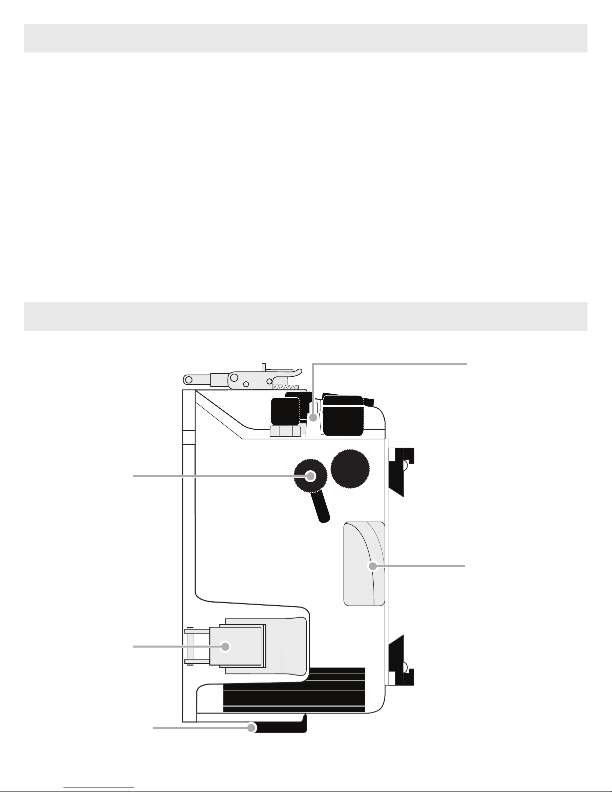
Parts of the Housing - Side View
Shutter Button
Lid-Snap
C1 Button
Finger Grip
External Tray Mount
6
Page 7
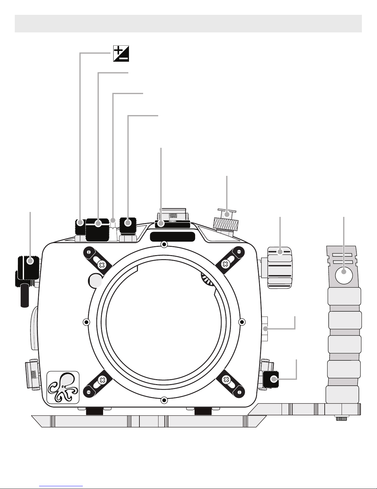
Parts of the Housing - Front View
Exposure Compensation Dial
ON/OFF Switch
C2 Button
Mode Dial / Lock Button
1/4-20 Light Accessory Mount
Front
Dial
Bulkhead Connector
Zoom Knob
Quick
Release
Push
Button
IKELITE
Accessory
Port
Lens Release
Button
7
Page 8
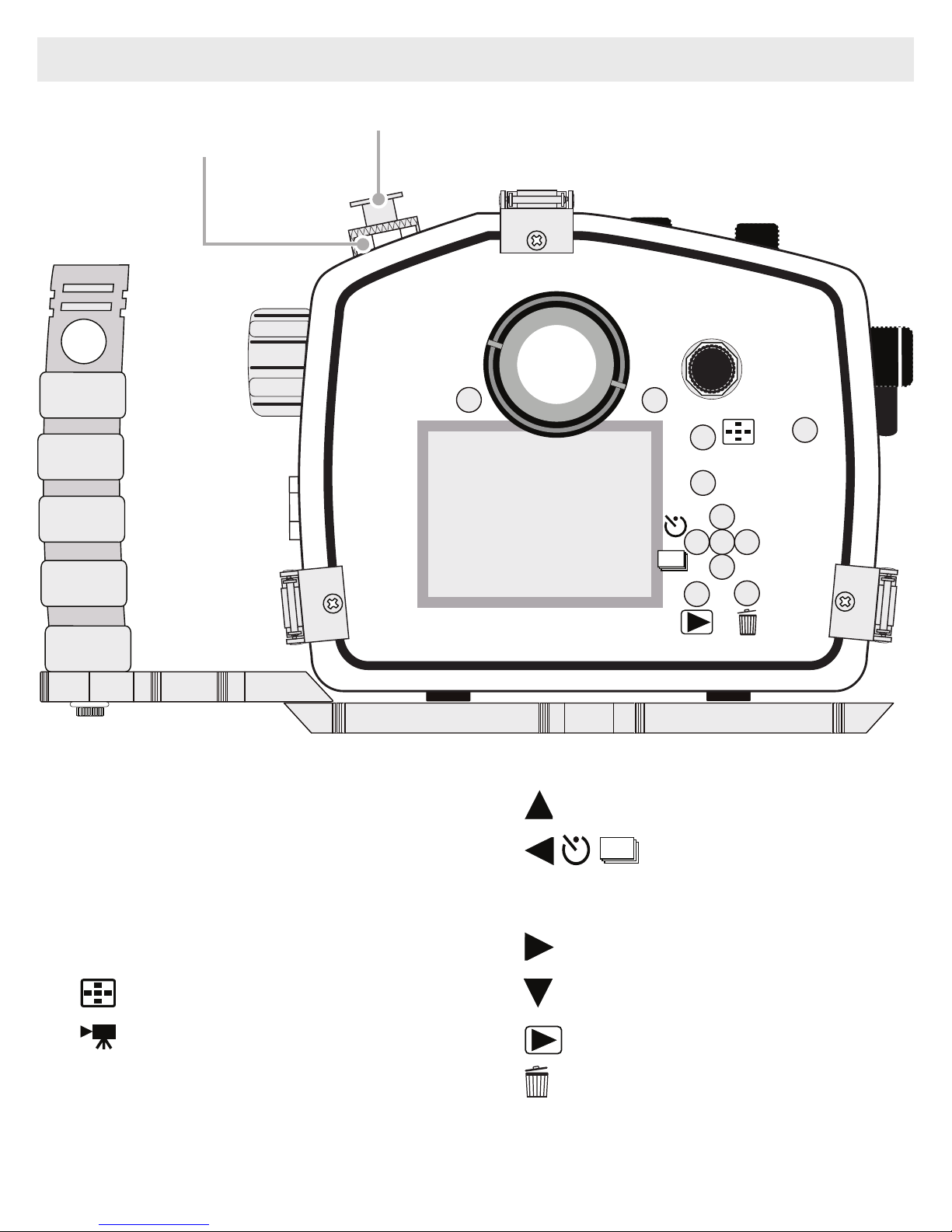
Parts of the Housing - Back View
Accessory
Port
Bulkhead Connector
2
MENU
1
C3
3
4
START/
STOP
5
Fn
7
DISP
8
1110
9
12
6
ISO
1. MENU BUTTON
2. Super-eye Viewnder
3. C3 (Custom 3) Button
4. Rear Dial
5. AF/MF / AEL Button
6. Movie START/STOP Button
13
14
8. DISP Display Button
9. Self-Timer/Down Cursor
10. SET Button
11. ISO / Right Cursor
12. Down Cursor
13. Playback Button
7. Fn Button
8
14. Delete Button
Page 9

HOUSING and CAMERA SETUP STEPS
Step 1 - Initial Camera Settings
- Insert a fully charged battery.
- Set Mode Dial to “A” Aperture Priority. Manually adjust aperture setting
to achieve the best exposure for your shooting conditions. The shutter
speed will be locked at 1/30th-1/60th second. If a faster shutter speed is
desired or you are NOT using an external strobe, set Mode Dial to “M”
Manual mode to manually adjust both aperture and shutter speed settings.
- In MENU settings:
Set Image Size to highest preferred setting.
Set Drive Mode to “Single Shooting” and Flash Mode to “Fill-ash.”
Set Red Eye Reduction to “Off.”
Set Focus Mode to “Single-shot AF” and Focus Area to “Center.”
Set AF Illuminator to “Off” and ISO to “200.”
Set Metering Mode to “Center” and White Balance to “Auto AWB.” Always
use auto white balance (AWB) when using a strobe/ash. When recording
video or still photos without a strobe, AWB can still be used, but for more
accurate and consistent colors we recommend setting Custom manual
white balance for each working depth. Custom manual white balance is also
recommended when using a color lter and no ash.
Set DRO/Auto HDR, Center Lock-on AF & Smile/Face Detect to “OFF.”
Set SteadyShot to “On” and Steadyshot Adjust. to “Auto.”
- In CUSTOM MENU settings,
Set Auto Review to “5 Sec.”
Set Eye-Start AF to “Off.”
Set FINDER/MONITOR to “Monitor”. This option turns off eye-piece
automation and must be set, otherwise, the camera will sense the housing
back and shut off the LCD screen transferring picture view to the optical
viewnder.
9
Page 10

Step 1 - Initial Camera Settings - continued
- In SETUP MENU settings:
Set Pwr Save Start Time to “5 min.”
* Allothercamerafunctionsnotmentionedshouldbesettotheuser’s
preference.
10
Page 11

Step 2 - Opening the Housing
Lid Snaps have a Lid Snap Lock.
1. Push Lid Snap Locks forward and lift as shown. Open opposing Lid Snaps
simultaneously. Keep pressure on the Lid Snaps so they do not y open
quickly. Some Lid Snaps have a lot of spring tension once they go over
center, so keep a rm grip on each Lid Snap. Lid Snaps may also be
opened one at a time.
2. Remove the Housing Back.
Push Forward
Lid
Snap
Lock
Lift
Step 3 - Install Camera in Housing
1. Make sure the camera battery is fully charged and a SD card is inserted into
the camera.
2. Pull top housing control knobs up for more clearance.
3. The Mounting Plate is secured to the inside bottom of the housing. The
camera Mounting Tray slides into the Mounting Plate. Use your index
nger and thumb to pull the Mounting Tray away from the Mounting Plate,
Diagram A, page 12. Use your other thumb to apply opposite pressure
against the bottom of the housing to assist in removal of the Tray if
necessary.
11
Page 12

Step 3 - Install Camera in Housing - continued
Diagram A
Pull to Remove
Mounting Tray Mounting Plate
4. Using a coin or athead screwdriver
(preferred), secure the camera Mounting
Tray to the camera tripod mount,
Diagram B. Tighten camera rmly to
avoid movement on tray. The Mounting
Tray only attaches one way with the
Mounting Tray Tab to the back of the
camera.
An additional 1/4-20-inch tray hole
allows attachment to a land tripod stand.
5. TURN CAMERA ON.
Wi Fi
Diagram B
Mounting
Tray Tab
Tighten here
6. Gently slide the camera with Mounting Tray back into the Mounting Plate,
Diagram C, page 13. Using your thumbs, push against the Mounting Tray
until it stops sliding forward into the Mounting Plate. Give the Tray an extra
push to make sure it is properly seated all the way forward in the Mounting
Plate and no housing controls are in the way.
12
Page 13

Step 4 - Attach Hotshoe
When connecting an external strobe to the housing bulkhead, slide the
hotshoe into the top camera mount until it stops. Hotshoe must be all the
way forward in the camera mount to assure a good electrical connection
with a strobe, Diagram C, below.
Turn Hotshoe Rotary Lock at hotshoe base clockwise to tighten to camera
mount.
Make sure hotshoe cord does not interfere with controls or the housing back
when closing the housing.
Diagram C
Hotshoe - push all the
way forward into the
camera mount
Push Camera and
Mounting Tray all
the way forward into
Mounting Plate
Hotshoe
Rotary
Lock
Wi Fi
Mounting Plate
13
Page 14

Step 5 - Closing the Housing
1. Place housing face down
Lid Hook
in your lap. Check to see
that there is an o-ring on the
housing back, and that it is
clean and in its proper location.
2. Guide the back onto the
housing front. Make sure the
hotshoe cord is out of the way.
Even gap on
all 4 sides
Once the back is properly
installed, the o-ring should
Lid Snap
touch the housing all the way around.
There should be an even gap on each side of the housing between the
housing and the back.
O-ring
3. Lift the lid snaps so they are extended and place each lid snap into the
corresponding hook on the housing back.
4. To close the housing, push down on the opposing lid snaps simultaneously
until they snap into place. Be sure they are down far enough to engage the
Lid Snap Lock - Page 11. The o-ring seal should now appear as a solid
black line when viewed from the back of the housing.
5. ATTACH Base + Release Handle to Housing bottom, page 23.
Step 6 - Final Check
This housing has been factory water pressure tested to 200 ft (60 m).
Once the housing is closed, recheck the o-ring seal. Double check the
gap between the housing back and the housing. It should be even all the
way around the housing. Look through the clear acrylic back at the o-ring.
You should see a darkened area or solid black line where the o-ring is
compressed against the housing back. If you do not see an even black
compression seal all the way around the back, open the lid snaps, reseat
the housing back, and reclose the lid snaps. Visually check the seal again.
14
Page 15

Step 7 - Housing Usage
Turn the camera on and operate each of the housing controls to get a feel
for using the camera in the housing.
Step 8 - Entering the Water
As soon as you enter the water, take a moment and check to see that the
housing is properly sealed. We recommend you rst water test the housing
with no camera inside to assure a safe and watertight environment.
Next, check to see if there are any bubbles on the face of the lens port. If
there are, take your nger and remove them. If there are bubbles on the
lens port they can produce soft focus spots in your photos or video.
Removing the Camera from the Housing
1. Thoroughly dry housing.
2. Remove the housing back, see Step 2, Opening the Housing, Page 11.
3. Remove the Hotshoe from the camera mount.
4. Pull back on both sides of the camera to begin releasing the Tray from the
Mounting Plate. Slowly and gently pull the camera backward to separate
from housing, Diagram D, Page 16. Continue pulling the camera backward
and remove from housing. We recommend doing this procedure on a
desktop or solid at surface to avoid dropping the camera.
If you are nished using the housing, remove the Mounting Tray from the
camera bottom and slide it back into the Housing Mounting Plate. For
storage and travel, remove the back o-ring, place in a small plastic bag.
Place the bag inside the housing and reattach the housing back.
Note: Camera must be removed from housing when changing a camera
battery or SD card.
15
Page 16

Removing the Camera from the Housing - continued
Remove Hotshoe. Grab and gently
Diagram D
pull backward on the camera and
Mounting Tray to remove from
housing.
Wi Fi
STROBE COMPATIBILITY and CONNECTION
Strobe Compatibility
• AF35 .................................. not compatible
• DS50 ................................. yes, above serial number 70000
• DS51 ................................. yes
• DS125 ............................... yes, above serial number 5000
• DS160, DS161 .................. yes
• DS200 ............................... yes, above serial number 7163
• Non-Ikelite ......................... yes, manual ash exposure only
• Fiber Optic ......................... not compatible
• Use built-in camera ash ... no
Housing Conversion Circuitry
This housing has Ikelite designed and patented Conversion Circuitry built
right in. The Conversion Circuitry provides real TTL ash exposure when
used with Ikelite DS series strobes. The circuitry is automatically activated
once a DS series strobe is attached to the housing and turned on. Once
attached, turn the strobe on rst before turning on the camera. The circuitry
cannot be powered up or used by non-Ikelite strobes.
16
Page 17

Attach Ikelite Sync Cord to the Housing and Strobe
The Ikelite Housing and Strobe Bulkheads are designed to accept sync
cords with Ikelite 5 pin connector ttings.
1. Lightly lubricate the Sync Cord O-rings. Use ONLY Ikelite lubricant (supplied
with housing). Other lubricants may cause the o-rings to swell and seal
improperly.
2. Remove Bulkhead Caps from Housing Bulkhead and Strobe Bulkhead.
3. Line up the Sync Cord Pins with the corresponding Bulkhead Receptacles.
Gently insert Sync Cord ends into each Bulkhead. Either Cord End may be
attached to a component. DO NOT force this installation. If the Sync Cord
does not seat properly inside the Bulkhead, then the Pins and Receptacles
are improperly aligned (repeat Step 3).
4. Tighten the Knurled Nuts snugly using your Index nger and thumb. DO
NOT use pliers or other tools to tighten the Knurled Nuts.
- Always remove the Sync Cord from your Housing and Strobe when not in
use and replace the Bulkhead Caps.
Diagram E
Ikelite 5-pin
Sync Cord
Knurled Nut
Sync Cord O-ring
Bulkhead Cap
Sync Cord Pin
Housing or Strobe
Bulkhead
17
Page 18

ZOOM CLAMP and GEAR SLEEVE INSTALLATION
Determine the type of lens being used on the camera.
Type 1 lenses have a lens opening that is NOT larger in diameter than
the zoom ring. The zoom clamp and sleeve can be attached over the lens
opening with the lens attached to the camera in the housing, Diagram I,
page 20
Type 2 lenses have a lens opening that IS larger in diameter than the zoom
ring. The zoom clamp and sleeve must be attached from the bayonet mount
end of the lens. The lens must then be attached after the camera has been
secured in the housing, Diagram J, page 20.
Type 1 Lens Type 2 Lens
Lens opening
Zoom ring
Bayonet mount
There are 2 different sets of Zoom Clamps and Gear Sleeves provided with the
housing. Both sets look similar, but are NOT identical. DO NOT mix the pieces
from both sets. Use the suggested Zoom Clamp and Gear Sleeve for your lens.
Go to ikelite.com for a complete list of compatible lenses.
The Zoom Clamp has springs so it can be expanded to t over the Zoom Ring
of the lens. Install the Zoom Clamp with the extension tabs toward the rear
element of the lens. After installing the Zoom Clamp and Gear Sleeve, install
the Lens Port and rotate the Zoom Ring on the lens. If the Zoom Ring and Gear
Sleeve do not mesh properly, install the rubber strips (supplied) to the inside
diameter of the Zoom Clamp as shown in Diagram H, page 19.
18
Page 19

Zoom Clamp and Gear Sleeve Installation - continued
Diagram F Diagram G
Zoom set 5509.27 Zoom set 5509.28
Lenses up to 2.8 in. diameter Lenses 2.8 - 3.0 in. diameter
Wide grooved
extension tabs
Long post
9059.8
Zoom
Clamp
0073
Gear
Sleeve
9059.9
Zoom
Clamp
Narrow grooved
extension tabs
Short post
0073.1
Gear
Sleeve
Two thicknesses of rubber strips are
provided with each Clamp. Start by
installing the thinnest rubber strips. If
the Zoom Clamp still is not tight enough
and meshes improperly with the Gear
Sleeve, use the thicker rubber strips.
Reinstall the Zoom Clamp and Sleeve.
Before installing the lens port and
checking operation, make sure the teeth
on the Gear Sleeve mesh with the teeth
on the housing Drive Gear, Diagram K,
page 20.
Diagram H
Apply rubber
strips to inside of
clamp as needed
19
Page 20

Zoom Clamp and Gear Sleeve Installation - continued
Diagram I Diagram J
Type 1 Lens Installation
When the port is installed, page 21, it
will lock the Gear Sleeve in place. After
installing the port, rotate the housing Zoom
Control Knob, Diagram K, to see that the
Gear Sleeve is properly rotating the Lens
Zoom Ring.
IKELITE
Type 2 Lens Installation
Port Lock
Release Button
Zoom Control
Knob
Port
Diagram K
Lock
Mesh Gear Sleeve
teeth with Black
Housing Drive Gear
Manual Focusing
Ikelite DSLR housings are designed for auto-focus DSLR cameras and lenses.
Manual focusing is not recommended. In some cases, if you desire to manually
focus a lens, the Zoom Clamp can be moved onto the lens’s Manual Focus
Ring. You can then use the housing Zoom Control Knob to manually focus. This
will result in loss of zoom capability.
20
Page 21

LENS PORTS
A lens port must be secured to the housing before entering the water.
Ikelite DSLR housings DO NOT come with a lens port. You must select
the correct port for each lens you will be using underwater. To assure
water-tightness, submerge the housing with port attached into a bathtub
or shallow water without the camera installed. This will conrm correct
installation of the port to the housing. For complete lens port information
and compatibility with your Ikelite system, go to ikelite.com.
Installing the Lens Port
There are four port locks on the front of the housing, see Diagram K, page
20. Each port lock has a Release Button. Lift the release button and slide
each Port Lock away from the port
opening. In the unlocked position,
Port Lock
Release Button
the Release Button will remain in
the up position as shown.
To prepare the port for installation,
remove and lightly lubricate
Locked Position
Lift Release
Button to Unlock
the port o-ring. The port seal is
a side-to-side seal and requires
the o-ring to be lightly lubricated
for easy installation. Put a small
Pull Back to
Disengage
amount of lubricant on your ngers and pull the o-ring
through your ngers to lightly lubricate it. Do not stretch the o-ring. Check
that the lip of the port where the o-ring ts and the sealing surface on the
housing are clean. Place the port, with o-ring, into the housing port opening.
Press down on the port rmly and evenly until you feel the port slide into
place. Continue to push down on the port and push each Port Lock forward
until the Lock fully engages. It may help to slightly rotate the port as you
push in on the port lock.
21
Page 22

Installing the Port - continued
Visually inspect each port lock and conrm that the Port Lock Release
Button is seated FLUSH against the Port Lock Body.
DO NOT rely only on an audible “click” to indicate that the lock is engaged.
Check around the perimeter of the port seal to see that the o-ring is properly
sealed and NOT extruded. It will be very difcult to close the Port Locks if
the o-ring is extruded or improperly seated.
It is NOT necessary to tighten housing port locks after installing a port. Port
locks are factory adjusted.
Slight port movement is normal after port locks have been closed and port
has been secured to the housing.
To REMOVE the port, lift up on each Release Button and slide the port lock
away from the port.
CAUTION: After installing the lens and port, turn the Zoom Control knob
on the housing. If the Zoom Control is difcult to turn, the Gear Sleeve may
be warped. If necessary, reduce or omit any rubber installed on the Zoom
Clamp, Diagram H, page 19. If the Zoom Clamp is still warped, use of the
5509.28 package may be required, see Diagram G, page 19.
22
Page 23

RECOMMENDED ACCESSORIES and ATTACHMENTS
4077.02 Right-Hand Quick Release Handle with Extension
The optional right-handed release handle with
tray mount comes with the necessary hardware to
mount to your Ikelite housing tray.
The Extension attaches to an existing Base with
two included screws for stability and rotation-free
use.
Attach Base + Release Handle(s) to Housing
1. Place the housing
upside down on a at
surface or in your lap,
so that the housing
port is facing toward
you as shown.
2. Line up the 2 triangular
shaped holes with the
housing mounts. If
the tray is positioned
properly, the handle
will be on your left side
facing down.
3. Insert and tighten both
1/4-20 x 3/8” screws
IKELITE
with nylon washers.
4. Finish tightening the tray to the housing using a athead screwdriver. DO
NOT overtighten.
23
Page 24

Attach Optional Strobe Arm to Housing
If you have purchased an optional Ikelite
Tray and Handle for your housing, an Ikelite
Strobe Arm will easily attach to the Handle
by depressing the spring-loaded Handle
Push Button until it stops. Gently slide the
pronged end of the Ikelite Arm into the hole
in the top of the Handle as shown.
When the Ikelite Arm is properly seated,
the Handle Push Button will return to it’s
starting position.
Ikelite Arm
Housing Handle
Housing Handle
Push Button
More Popular Accessories
- Vega Video + Photo Light
- 2602.2 Flex Mount Kit for GoPro
- Gamma II Waterproof Flashlight
- 1887.1 DSLR Ball Mount Kit for Gamma
A full range of accessories are available to support your housing. Please
visit ikelite.com to see the most current information about recommended
accessories for your housing.
24
Page 25

SPARE PARTS - available through Ikelite or any Ikelite Dealer
• 5512.68 Spare o-ring set with main o-ring, port o-ring and lubricant
• 0132.59 Main o-ring
• 0105 Port o-ring
• 9104.5 Waterproof bulkhead cap
• 0200.91 Housing body cap
• 0184.2 Silicone lubricant resealable 2cc tube
MAINTENANCE
Lens Port
Treat the surface of the lens port as a camera lens. After use, rinse and
gently dry the outside lens port to avoid water spotting. To clean, use a mild
soap solution or lens cleaner. It is NOT necessary to remove the Port for
cleaning. Do not rinse the inside of the Port.
Do not use alcohol or window cleaner on the Lens Port.
O-ring Storage
When storing the housing, remove the main housing o-ring. Lightly lubricate
the o-ring until it appears shiny and place in a small resealable plastic bag.
Use ONLY Ikelite lubricant. Place the bag inside the housing and store until
needed.
25
Page 26

Lubricant
Ikelite provides silicone lubricant with the housing to lightly lubricate controls
and o-rings. We recommend you use ONLY Ikelite lubricant on Ikelite
products. Other brands may cause the main housing o-ring to swell and
not seal properly. Lubricant is not needed on the main housing o-ring to
maintain a housing seal, however, lightly lubricating this o-ring can extend
it’s life and aid in seeing a good housing seal.
Wipe off any excess lubricant with a clean cloth. Lubricant is not a sealant;
it is used to reduce friction. Excessive lubricant can collect sand, hair or
debris which may interfere with proper sealing.
CAUTION: Never use spray lubricants as the propellant ingredient can
cause the plastic housing to crack or o-rings to swell.
Housing Maintenance
Your Ikelite Digital Housing should be given the same care and attention
as your other photographic equipment. In addition to normal maintenance,
we recommend that the housing be returned to Ikelite periodically to be
checked and pressure tested.
- Do not leave the camera and housing in direct sunlight for prolonged
periods. Heat may damage the camera.
- Do not ship the camera in the housing.
- Before using the housing, always check the tightness of the set screw in
each control knob. Check each control gland penetrating the housing to
make sure they are tight. There is a slight chance that either could vibrate
loose during travel.
- Keep the main housing o-ring clean and lightly lubricated. To lubricate,
remove the o-ring from the back. Put a small amount of lkelite lubricant on
your ngers. Pull the o-ring through your ngers to apply a thin coating of
lubricant. Only apply enough lubricant to make the o-ring feel slick.
Do not stretch the o-ring.
26
Page 27

Housing Maintenance - continued
This light coating of lubricant will help to keep the o-ring from drying out
and will help to show a dark sealing line when the housing back is properly
sealed.
- Keep area where the o-ring ts and sealing surface of the housing clean.
- Rinse the housing exterior thoroughly in freshwater after each saltwater
use. Depress push buttons repeatedly in freshwater to eliminate trapped
saltwater. Dry with a soft cloth. Dry lens port to eliminate water spotting.
After several uses in saltwater, soak the housing exterior in a mild soap
solution; rinse and dry before storing. When storing the housing, remove
the back o-ring, lightly lubricate, and place in a plastic bag. Place the plastic
bag with o-ring inside the housing for safe keeping.
- If removing a housing push button, Do Not re-use the E-clip. Contact Ikelite
for replacement E-clips (part 0319.12).
- Leave lid snaps in the open position when not using the housing for
extended periods.
- Always disassemble and clean the housing Tray/Handle(s) before storage.
Over time, corrosion can make components difcult to disassemble.
Control Maintenance
Ikelite controls are designed to provide years of reliable service with
minimal maintenance.
- Push button controls normally require no maintenance other than rinsing
in freshwater after saltwater use. Depress each push button in freshwater
several times to eliminate trapped saltwater. If a push button control
becomes difcult to push or if it sticks when depressed, soak the housing in
luke warm freshwater. After a few minutes, operate the push button. If this
does not correct the problem, return the housing to Ikelite for maintenance.
If you are on a trip and unable to return the housing immediately, a push
button may be lubricated by pressing and holding the push button all the
way in. Then, use your nger or other small non-metal object to place a
small amount of lube at the base of the shaft inside the housing.
27
Page 28

Control Maintenance - continued
Press and release the push button
several times until the lube is worked
up into the o-ring.
After completing this procedure, close
Diagram H
the housing and submerge it in water
without the camera i nside.
Check the
control for watertightness.
- Although not recommended, if it is
necessary to remove a housing push
button, DO NOT re-use the E-clip.
Contact Ikelite for replacement E-clips
(part #0319.12).
Apply Ikelite
Lube Here
Ikelite controls are designed to provide years of reliable service
with minimal maintenance.
In the unlikely event one of the control shafts sticks or becomes difcult to
operate, you can remove the control from the housing and lubricate it, or
return the housing to Ikelite for maintenance.
Your housing may feature both round and hex style control glands. To
remove a control in a round style gland, Diagram I, page 24, loosen the
set screw in the knob (allen wrench required); remove the knob. If there is
salt or dirt build-up on the exposed control shaft, clean the shaft. Open the
housing and gently slide the control shaft out of the control gland. Clean
and lightly lubricate the shaft and o-rings, including the large end of the
shaft.
If there is a shutter spring on the Control Shaft, make sure it is in its proper
position. Rotate the Shaft back and forth slightly to aid installation back into
the Control Gland. Replace the knob with the Set Screw over the Control
Flat. The Set Screw in the knob should be tightened down against the at
area on the Control Shaft so the knob does not turn on the shaft.
28
Page 29

Control Maintenance - continued
- Some of the controls have long shafts and feature a hex style control gland.
These controls can be pulled out, exposing the shaft, Diagram J, page 30.
To lubricate the control, gently pull on the knob until the stainless steel
shaft is exposed. Lightly lubricate the shaft, then move the shaft in and out
several times. This will lubricate the x-ring in the Ikelite control gland. This
should be done before using the housing after a prolonged storage period,
or once a week when the housing is in constant use.
- Some of the controls have a short shaft and cannot be pulled out exposing
the shaft for lubrication. In the unlikely event one of these controls sticks or
becomes difcult to operate, you can remove the control from the housing
and lubricate it, or return the housing to Ikelite for service. To remove the
control, Diagram K, page 30, loosen the set screw in the knob (allen
wrench required); remove the knob. If there is salt or dirt build-up on the
exposed control shaft, clean the shaft. Open the housing and gently slide
the control shaft out of the control gland. Clean and lightly lubricate the
shaft, including the end of the shaft. Slide the shaft back into the control
gland and gently slide the shaft back and forth a few times without fully
removing the shaft from the gland. Replace the knob noting the at area
on the shaft. The set screw in the knob should tighten down against the at
area on the control so the knob does not turn on the shaft.
Close housing without a camera inside and water pressure test in a
bathtub or swimming pool. Rotate* the knobs to make sure the housing is
watertight and the gland was installed properly. Check all controls while the
housing is submerged.
*Caution: If your housing has a shutter spring, DO NOT rotate the shutter
control more than 1/16th of a rotation, otherwise, you may accidentally bend
the shutter spring or cause the spring to “pop off” the control shaft.
29
Page 30

Control Maintenance - continued
Lubricate end of shaft
before reinserting into
Diagram I
gland
Control
Shaft
O-rings
Tighten set screw down against this
at area when replacing the knob
Diagram J
Loosen Set Screw
(Hex Head Wrench Required)
Knob
Control Gland
Housing
Lubricate Shaft
Housing
Tighten set screw down against this
at area when replacing the knob
Diagram K
Control
Shaft
Lubricate end of shaft
Pull out shaft
to expose shaft
Control Gland
Loosen Set Screw
(Hex Head Wrench Required)
before reinserting into
gland
30
Page 31

PHOTO TIPS
- The number one rule in underwater photography is to eliminate as much
water between the camera and subject as possible. Get as close as you
can to the subject, then use the zoom. If you are using ash for still photos,
subjects beyond 6 ft (1.8 m) will not have much color regardless of strobe
power.
- Photograph in clear water; do not stir up the sand or silty bottom. If
backscatter becomes a problem in the environment you are photographing,
an external ash will help eliminate much of the backscatter.
- Many digital cameras have a slight lag time between when you press the
shutter release button and the camera actually takes the picture. Hold the
housing steady a second or two after pressing the shutter release button.
- Do not shoot down on subjects as they will quite often blend into the
background and be difcult to see in the photograph. Shoot subjects
straight on or shoot up at a slight angle using the blue water as a
contrasting background.
- When using daylight or ash, if your camera consistently over or
underexposes the image, you may want to adjust your camera’s exposure
compensation settings.
- If you error in exposure, it is better to have the image slightly underexposed
rather than overexposed. An overexposed image is missing color
information which cannot be adjusted in a photo processing program. A
slightly underexposed image has color information that can be adjusted.
- It is important to respect all living creatures underwater, including people,
marine life, and coral. While we encourage people to get close to their
subjects when taking a photograph, we recommend they not touch, lie on,
or in any way disturb the things they nd underwater.
31
Page 32

TROUBLESHOOTING
Problem
Push buttons or
controls are sticky
or hard to operate
Solution
- Remove the camera and rinse the closed housing
in freshwater. Vigorously press each push button
in and out several times to release any trapped
saltwater or debris.
- Press a sticky push button all the way in and
place a small amount of lube on the small end of
the push button shaft at it’s base. Release and
depress the push button several times to distribute
the lube, Diagram H, page 28.
- If a larger gland style control is sticky, grab the
control knob, pull it out, and then push back in. If
still sticky, see the Control Maintenance section,
Image is over/
underexposed, or a
corner of the image
is dark
pages 27-30.
- Return housing to Ikelite for routine service
- Check that the external strobe is ring when taking a
picture. Camera ash should be forced “on” .
- When using an external strobe, make sure it is
turned on, set properly, and its battery is charged.
- Check all corded connection points.
- Adjust camera shutter speed, aperture, exposure
compensation, or a combination of these.
- Move closer to or further away from the subject.
32
Page 33

Problem
Solution
Camera does not
take a picture or
focus properly
Housing is hard to
close
- Install a fully charged battery.
- A housing control is engaging a camera function and
will not allow the shutter to re.
- There is not enough available light for the camera
to properly focus. Add a focusing light or strobe
with a built-in focusing or video light to your
system.
- Select a center focus point in your camera menu.
- Add a +4 diopter (close-up lens) to your camera lens
when using a dome port underwater.
- Make sure the camera is mounted properly in the
housing and controls/cord are out of the way.
Fogging occurs on
the Lens Port
- Main housing o-ring is not seated properly.
- Humid air is trapped inside the housing.
The camera produces heat and may condense
any trapped moisture forming fog on the lens port.
Close the housing in an air-conditioned room or
vehicle, or in front of an air-conditioner.
- The housing should not be in direct sunlight for an
extended period of time.
- Purchase desiccant packs from a local camera store.
Place one or two new packs in your housing before
each day of diving.
- Clean the main housing o-ring and sealing
surface of the housing.
- If moisture or water droplets are present around
the controls or sealing areas, return the housing
to Ikelite for evaluation.
33
Page 34

Problem Solution
Water enters the
housing
Pictures are too
blue or too green
- Remove, clean and properly lubricate the main
housing and port o-rings.
- Look for hair, dirt, or foreign debris crossing the
o-ring seal.
- Reassemble the housing without a camera
installed and pressure test or take diving.
- Return housing to Ikelite for routine service.
- Move in closer to your subject when taking a
picture.
- Use custom (manual) white balance. Reset for
each working depth or when attaching a
color correcting lter to the camera lens.
- Add an external strobe.
- Strobe is not ring. Check corded connection
points and strobe battery levels..
CUSTOMER SUPPORT
Please read the troubleshooting section of this instruction manual before
contacting Ikelite Customer Support.
Ikelite Underwater Systems
Service Department
50 West 33rd St.
Indianapolis, IN 46208 USA
Email: ikelite@ikelite.com | Phone: 317-923-4523
34
Page 35

LIMITED WARRANTY
This Ikelite product is warranted against any manufacturing defects for a
period of one (1) year from the original date of purchase. Defective products
should be returned to Ikelite postage paid. Ikelite will, at its sole discretion,
repair or replace such products, and will return to customer postage paid.
All other claims of any nature are not covered. Except as mentioned above,
no other warranty expressed or implied applies to this Ikelite product.
RETURNING PRODUCTS FOR SERVICE
Ikelite is most interested in performing any service to ensure that all
products perform as intended. Evidence of purchase date must be provided
to obtain warranty service.
No prior authorization is required. You may return directly to us or through
your dealer. Please include a brief description of the problem, any relevant
email correspondence, and/or instructions on what you want us to do.
Always include name, shipping address, email address, and phone number
inside of the package. Send postage paid to:
Ikelite Underwater Systems
Attention: Service Department
50 West 33 Street
Indianapolis, IN 46208 USA
No reimbursements for postage paid will be issued.
You may also want to insure the package.
Returning Products for Service - outside the United States
For the separate international customs documentation form that you
complete to accompany the shipment, please state or designate that the
enclosed products were originally manufactured in the USA and are being
returned to the manufacturer for repair service. Value of the equipment
listed for customs purposes should be zero.
35
Page 36

PRODUCT REGISTRATION
Please go to ikelite.com to register your Ikelite housing within 15 days of
purchase.
Ikelite Underwater Systems
50 West 33rd Street
Indianapolis, IN 46208 USA
ikelite.com
© 2016 Ikelite Underwater Systems
6843.72_sony-a7II_a7rII_a7sII_1-0116
 Loading...