

Page 1
2
P R O - 2 8 0 0 L E D V i d e o L i t e
I n s t r u c t i o n M a n u a l
Thank you for your purchase of Ikelite Underwater equipment. Ikelite products have been designed and
built in the USA since 1962 by Ikelite for both the professional and amateur photographer.
This product should receive the same care and attention as your other photographic products.
Introduction
Normally, images recorded underwater have a blue-green cast because water absorbs the warmer
colors from the ambient light. The Ikelite PRO-2800 Lite helps you add the important dimension of
color to your recorded images. Turn on the PRO-2800 Lite and your subjects will “pop-out” from the
background in living color.
The Ikelite PRO-2800 Lite features an ultra-compact light head incorporating 9 super bright LEDs.
Unsurpassed performance is achieved with an ultra-wide 100° angle of coverage that is free of hot
spots with 5000-5500° K color temperature.
Although designed for use with all of Ikelite’s newer Video and Compact Video housings, the
PRO-2800 Lite can also be attached to the base of a DSLR tray to capture video from a Digital SLR
camera.
The battery pack slides quickly and easily into a battery pouch underneath the housing providing
good weight distribution, and will accept one or two lite heads.
Note regarding “out of water” use:
This product is not designed for above water use. Water helps cool the lite head. When the
PRO-2800 is used out of the water, the light will only run for approximately 2 minutes at full
brightness, then the light will shut off to protect the unit from overheating.
- Please read all instructions before using this product.
SAFETY NOTICE: The PRO-2800 Battery Pack should never be secured directly to a diver
because its cord connects to the lite head that will be secured to a housing connection. In the event
of an emergency, the diver would be unable to free him/herself from the housing, creating an
extremely dangerous, potentially life threatening situation.
Table of Contents
Pg 1 ............................................ Introduction
Pg 2 ............................................Safety Notice - Table of Contents - PRO-2800 Specifications
Pg 3 ............................................PRO-2800 Operation and Power Settings
....................................................PRO-2800 Battery Capacity
....................................................PRO-2800 Package System Assembly
Pg 4 ............................................#6328.01 PRO-2800/SA-100 Ball-Socket Arm Complete Package
....................................................#6328.02 PRO-2800/Flex Arm Complete Package
Pg 5 ............................................#6328.11 PRO-2800/SA-100 Ball-Socket Arm Conversion Package
....................................................#6328.12 PRO-2800/Flex Arm Conversion Package
Pg 6 ............................................PRO-2800 Arm Mounts
....................................................PRO-2800 Power Cord Preparation and Attachment
Pg 7 ............................................NiMH Battery Pack #1400.8
....................................................Pro/SpD Charger #1403.4
Pg 8 ............................................Charging the Battery Pack
Pg 9 ............................................Attach Battery Pack to Video Housing
....................................................Tray setup and Battery Pack Attachment
Pg 10 ..........................................Attach PRO-2800 to Video Housing with the SA-100 and Flex Arm
Pg 10-11......................................Attach Battery Pack to DSLR Housing
Pg 12 ..........................................Attach PRO-2800 to DSLR Housing
....................................................Attaching the PRO-2800 Lite Head and Flex Arm to Top Mount
....................................................Attaching the PRO-2800 Lite Head and SA-100 Arm to Top Mount
............................................................Optional Stem Mount connects Flex Arm to Quick Release Handle
Pg 13 .......................................... Attach Battery Pack to Compact Video Dual Tray
Pg 14 ..........................................Attach PRO-2800 w/SA-100 Arm to Compact Video Dual Tray
....................................................Attach PRO-2800 w/SA-100 Arm to Compact Video Dual Handles
Pg 15 ..........................................Attach PRO-2800 w/Flex Arm to Compact Video Dual Tray
....................................................Attach PRO-2800 w/Flex Arm to Compact Video Dual Handles
Pg 16 ..........................................Optional Accessories and Spare Parts
Pg 16-17 ....................................Ikelite PRO-2800 Care and Maintenance
....................................................Routine Cleaning
Pg 17 ..........................................Long Term Storage - Lubricant - Flooding
....................................................Pro Video Lite II / 3 Conversion
Pg 18 ..........................................Returning Products for Service
....................................................Returning Products for Service (outside the United States)
Pg 19 ..........................................Ikelite Limited Warranty
Pg 20 ..........................................Ikelite Technical Support
PRO-2800 Specifications
Intensity: 2800 lumens (High power)
.700 lumens (Flashlight)
Power Settings: Flashlight (1/4), Full, 3/4, 1/2, SOS
Burn Time: 1 hour 30 min (Full power)
2 hours 45 min (1/2 power)
4 hours 30 min (1/4 power, Flashlight)
Beam Angle: 100 degrees
Color Temp: 5000-5500K
Battery: 13V 4.5Ah NiMH
Depth Rating: 90m (300ft)
Size: 2.75” (7cm) diameter x 3.3” (8.4cm) length
Weight: .75 lbs.
Depth Rating: 90m (300ft)
#6 3 2 8 . 0 1 PR O - 2 80 0 wi t h S A- 1 0 0 A r m Pa c k a ge
#6 3 2 8 . 0 2 PR O - 2 80 0 wi t h F le x A r m Pa c k a g e
#6 3 2 8 . 1 1 P R O -2 8 0 0 wi t h SA - 1 0 0 A r m C on v e r s i o n P a ck a g e
#6 3 2 8 . 1 2 PR O - 2 80 0 wi t h F le x A r m Co n v e r s io n Pa c k a g e
Page 2
IKELITE #0184.1
Silicone Lube
IKELITE #0184.1
Silicone Lube
3 4
SOS
Made in USA
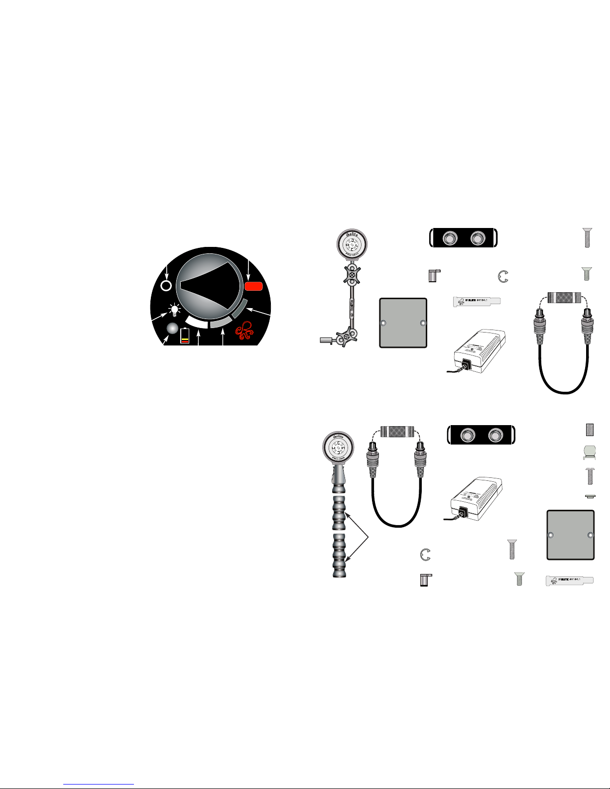
Back View
P
ower: On/Off
Full
Power
Flashlight
1/4 Power
3/4
Power
1/2
Power
“SOS” Mode
Fuel Guage
Indicator Light
Power
Switch
Power Settings
Flashlight (1/4 power) can be used
to conserve power when not
shooting video or shooting a very
close-up subject.
Full, 3/4, and 1/2 power are the
normal video shooting modes. Set
power accordingly based on
distance to subject, water clarity,
and ambient light.
“SOS” mode emits 3 short and 3 long
flashes, alternately. This is the
international distress signal and
should only be used in an
emergency.
PRO-2800 Package - System Assembly
1. First make sure you have all the components listed in your PRO-2800 Lite package - Pages 4-5.
2. Using a phillips screwdriver, attach the arm mount to the Lite Head if not already done - Page 6.
3. Remove Cord Protector Cap from Power Cord - Page 6. Lightly lube each Cord End o-ring. Use
only Ikelite lube (supplied); other lubricants may cause the o-rings to swell and not seat properly.
Wipe off excess lube with a clean cloth. Make sure there is no hair or debris on the o-rings.
4. Attach one Cord End to the PRO-2800 Lite head - Page 6, Diagram A. Either Cord End can be
used.
5. Remove the Battery Pack from the Battery Pack Pouch.
6. Plug in the Smart Charger to fully charge your Battery Pack - Page 8, Diagram D.
7. Attach the Battery Pack to your specific system tray: Page 9 for a Video Housing Tray,
Pages 10-11 for a DSLR Housing Tray, and Page 13 for a Compact Video Dual Tray.
8. Attach the PRO-2800 Lite with arm to your system: Page 10 for a Video Housing, Page 12 for a
DSLR Housing, Pages 14-15 for Compact Video Housing.
9. Attach the remaining Power Cord End to a Battery Pack Female Connector.
10. Rotate Power Switch counter-clockwise to turn Lite on - see above.
PRO-2800 Operation & Power Settings
The PRO-2800 Lite features a rotational Power Switch. After the system is assembled and the
PRO-2800 is attached to a charged Battery Pack, rotate the switch counter-clockwise from the
On/Off position to your desired power setting. Rotate switch clockwise from your chosen power
setting to turn Lite off. Note that switch will NOT rotate clockwise past the On/Off position or
counter-clockwise past the “SOS” Mode position.
PRO-2800 Battery Capacity
Battery Capacity: Fuel Guage Indicator Light Color = Capacity Remaining
- GREEN = 100% (full charge) to 70% remaining power.
- YELLOW = 69% to 40% remaining power.
- RED = 39% to 10% remaining power.
- RED BLINKING = 9% TO 0% power remaining.
When indicator light is blinking red, time remaining is approximately 10 minutes at full power. To
increase run time, decrease power level.
#6328.01 PRO-2800/SA-100 Ball-Socket Arm Package
P
RO-2800 LED
L
ite Head
SA-100 Ball
Socket Arm
B
attery Pack with Pouch
Mounting Plate
E
-
clip:
Q
t
y.
2
M
o
u
n
ti
n
g
N
u
t:
Q
ty
. 2
1
/4-20 x 1”
Flathead Screw:
Qty. 2 (Video)
1
/4-20 x 5/8” Flathead
Screw: Qty. 2 (DSLR &
Compact Video)
Smart Charger with
4 adapter plugs
#6328.02 PRO-2800/Flex Arm Package
1/4-20 x 7/8”
Screw
Flex Mount
Shoulder Washer
E-clip: Qty. 2
Mounting Nut:
Qty. 2
1/4-20 x 5/8” Flathead
Screw: Qty. 2 (DSLR &
Compact Video)
1/4-20 x 1”
Flathead Screw:
Qty. 2 (Video)
Knurled Nut
PRO-2800 LED
Lite Head
Battery Pack with Pouch
Smart Charger with
4 adapter plugs
Mounting Plate
Lube
Incl ud ed in Co mplete Pac ka ge
Power Cord
Flex Arm
Cord
Cap
Power Cord
Cord
Cap
Lube
Incl ud ed in Co mplete Pac ka ge
Page 3
IKELITE #0184.1
S
ilicone Lube
IKELITE #0184.1
Silicone Lube
5
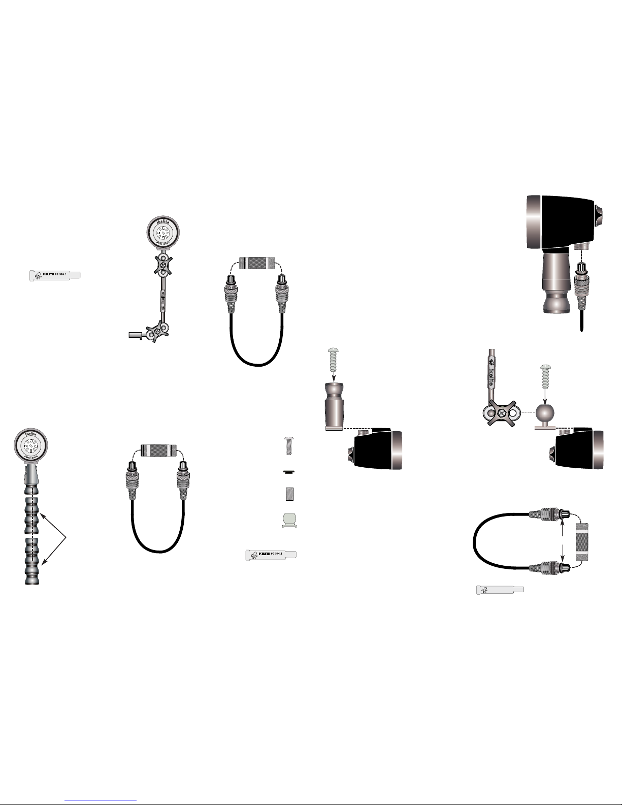
#6328.11 PRO-2800/SA-100 Ball-Socket Arm Package
PRO-2800 LED
L
ite Head
SA-100 Ball
Socket Arm
L
ube
#6328.12 PRO-2800/Flex Arm Package
Flex Arm
1/4-20 x 7/8”
Screw
Flex Mount
Shoulder Washer
Lube
Incl ud ed in Co nversio n P ac ka ge
PRO-2800 LED
Lite Head
Knurled Nut
Diagram A
PRO-2800 Arm Mounts
To add, remove or change an Arm Mount, the Power Cord must first
be removed from the Lite Head.
- To remove a Flex Arm Mount, break apart the Flex Arm pop-beads
leaving the first pop-bead attached to the Flex Arm Mount Diagram A. Turn the Lite upside down. Insert a phillips screwdriver
into the Flex Arm Mount through the open pop-bead. Remove
Screw and slide the mount toward the back of the Lite Head to
remove.
When re-attaching, the recessed part of the mount should be slid
into the Lite Head first. Reverse procedure to add or re-attach Diagram B.
- To remove the SA-100 Ball-Socket Mount - Diagram C, turn the
Lite upside down.
Loosen the Ball Socket Clamp wingnut closest to the Lite Head and
rotate the clamp toward the back of the Lite Head. Insert a phillips
screwdriver into the Ball Mount hole. Remove screw and slide the
mount toward the back of the Lite Head to remove. Reverse
procedure to add or re-attach.
Flex Arm Mount
C
ord
End
1/4-20 x 3/4”
Screw
Diagram B
1/4-20 x 3/4”
Screw
Diagram C
Ball Mount
PRO-2800
Lite Head
PRO-2800
Lite Head
SA-100
Ball-Socket
Arm
IKELITE #0184.1 IKELITE #0184.1
Silicone Lube
Ikelite Lube
PRO-2800 Power Cord Preparation and Attachment
1. Remove Cord Protector Cap from Power
Cord and lightly lube each Cord End o-ring.
Use only Ikelite lube (supplied); other
lubricants may cause the o-rings to swell
and not seat properly.
2. Wipe off excess lube with a clean cloth.
Make sure there is no hair or debris on the
o-rings.
3. Make sure your Arm Mount is securely
attached to the PRO-2800 Lite Head. To
remove or attach an Arm Mount, see
Diagrams B & C above.
4. Attach one Cord End to the PRO-2800 Lite
Head - Diagram A. Either Cord End can be
used.
6
Power Cord
Cord
Cap
Power Cord
Cord
Cap
Cord
Cap
#4103.50
Power Cord
O-rings
Incl ud ed in Co nversio n P ac ka ge
Page 4

7
8
NiMH Battery Pack #1400.8
Caution: The battery pack is factory sealed. Do not disassemble. Disassembly will void your Ikelite
product’s limited warranty.
The rechargeable battery pack consists of nickel metal hydride batteries (4.5 Ah rating). Per charge,
the pack can power a PRO-2800 Lite for approximately 1 hour and 30 minutes at full power.
Two lite heads can be connected to the battery pack for greater intensity,
however burn time will be reduced.
To increase burn time, two battery packs can be stacked in a
#1401.2 double battery pack pouch (sold separately) and
connected to two lite heads. Or, you could attach two packs to
one lite head and double its burn time. Optional Battery
Jumper Cable #1405.06 is needed when using only one
PRO-2800 Lite with two packs (See “Optional Accessories &
Spare Parts” on Page 16).
Caution: The battery pack’s female connectors are not
waterproof and must be capped when not connected to an
Ikelite cord. Using a battery pack underwater with one or both
of the female connectors uncapped or unconnected to a cord will cause the pack to flood. Do not
reuse a battery pack that has flooded (See “Flooding” on Page 17).
Caution: Do not block or tamper with the vent on the battery pack. Normal evolution of all batteries
includes the emission of hydrogen gas. This gas must be absorbed or allowed to escape to prevent
ignition of the entrapped hydrogen/air mixture. A hydrogen absorber has been installed inside the
battery pack for this reason. The vent port on the battery pack allows hydrogen/air mixtures to
escape. The Ikelite battery pack pouch safely covers this vent.
Single Battery Pack Pouch
Waterproof
Cap
Female
Connector
(Cap Removed)
Double Battery Pack Pouch
Vent on Back of Pack
“”Do Not Block”
Using the Charger
Note: The Ikelite 10 Cell/12 Volt Pro/SpD Smart Charger is not
compatible with the NiMH Battery Pack #1400.8
PRO/SpD Charger #1403.4
The Ikelite Pro/SpD Charger #1403.4 is compatible with the NiMH
Battery Pack #1400.8 featured on the Ikelite SpD and Pro Video-Lite
systems (it is also compatible with the older NiCad Battery Pack #1400).
- This charger is not compatible with Ikelite substrobes.
- Charger cords (#0171.61, #0171.62, #0171.63) for the original smart
chargers (#1403.1, #1403.2, #1403.3) are not compatible with the
Pro/SpD Charger #1403.4.
#1403.4 PRO/Spd
Smart Charger
Charging the Battery Pack
Warning: Do not attempt to charge the battery pack when it is still wet. Electrical shock, injury, or
fire could occur. Make sure all components are completely dry.
- Charge the battery pack after purchase and recharge after each use. To charge the pack, please
read the following instructions:
1. Make sure all components are dry. If attached, rotate the PRO-2800 Lite head switch to the OFF
position.
2. Unscrew and remove the waterproof cap or lite head cable.
3. Align and insert the Smart Charger Cord End into either female connector on the battery pack
- Diagram D.
4. Screw the knurled ring of the Cord End onto the female connector. Make sure the connection
is good and secure.
5. Plug the charger into the wall and charge the pack. See the charger instructions for details on
charging times.
6. After charging, replace the waterproof cap.
Store the battery pack fully charged. Remove it from storage every few months and fully recharge it.
Diagram D
Battery Pack
Female Connector
with Waterproof Cap
Smart Charger
Cord End
Always store your packs in a dry location at a temperature of less than 30°C (86°F). You will not
damage your pack by storing it for long periods of time without charging it. Approximately 20-40% of
the packs capacity will drain when left idle for a month. This is normal and unavoidable. The lost
capacity will be recovered after two or three charger/discharge cycles.
You may wish to charge your battery pack every couple of months to maintain its capacity for peak
performance on the first few uses your next dive trip.
Female Connector with
Waterproof Cap removed
Page 5

9 10
Attach Battery Pack to Vid eo H ous ing
Tray Setup and Battery Pack Attachment (Diagrams E, F & G)
1. Rotate base toggle and remove base from tray.
2. Place a video tray Mounting Nut into the video tray slot from the handle side of the tray. Slide
the round end to the round end of the tray slot.
3. Flip the tray over holding the mounting nut in the tray slot. Push an E-clip into the Mounting
Nut groove. The use of needle nose pliers may assist you in properly seating the E-clip:
Diagrams E, F & G.
4. Repeat the process with the remaining Mounting Nut and E-clip.
5. Re-attach the tray to the housing. Leave housing upside down.
6. Remove Battery Pack from Battery Pack Pouch.
7. Insert the longer 1/4-20 x 1” screws into the Mounting Plate so the screw heads are flush with
the textured side of the Plate.
8. Insert Plate with Screws into the Battery Pouch. Screws will protrude through Pouch holes
opposite the Ikelite logo.
9. Position Pouch so that the flap is facing towards back of housing.
10. Slide a phillips screwdriver through the logo side pouch holes and tighten both screws into
Mounting Nuts.
11. Insert Battery Pack into Pouch so that the Female Connectors face toward the back of the
housing. Close Flap over the Bulkheads.
12. Remove one Female Connector Cap and attach either end of the Power Cord. Hand tighten
only.
- If using two Battery Packs, see Page 7.
Mounting Plate
Mounting Screws
Battery Pack
Pouch Flap
Battery Pack
Pouch
P
o
w
e
r
C
o
r
d
Video Tray
and Handles
“back view”
E-Clip
Mounting Nuts
Diagram F
Diagram E
Diagram G
1. When using the SA-100 ball socket arm, slide arm mount and 3/8” washer over handle stud,
tighten Wingnut.
2. Attach one Cord End to the Battery Pack and the other to the PRO-2800. Either Cord End can
be used for a component.
3. When using the Flex Arm, slide the Ball Mount over handle stud and hand tighten with the
Knurled Nut. It is not necessary to use any tools such as pliers to tighten the ring as this could
result in stripping of the Nut threads.
4. Grab the base of the Flex Arm with the PRO-2800 attached and push it onto the Ball Mount to
secure it to the handle. Firm pressure is necessary to attach the components.
Attach PRO-2800 to Vid eo H ous ing wit h th e SA -10 0 Ba ll
Socket Arm and Flex A rm
B
a
ll Mo
u
n
t
K
n
u
r
le
d
Nu
t
Handle St
ud
Battery Pack
Cor
d End t
o
Bat
t
ery Female
Connect
or
W
in
g
n
u
t
3
/
8
”
W
a
sh
e
r
SA-100
Ball-
Socket
Arm
A
r
m
Mo
u
n
t
Co
r
d
E
n
d
t
o
P
RO
-
2
8
0
0
Fle
x
A
r
m
Attach Battery Pack to DSLR Housing
1. Turn the housing upside down so the Battery Pack attachment holes on the bottom of the tray
are facing up and to the back of the housing as shown in Diagram H - Page 11.
2. Loosen and adjust the Housing Tray (move forward or backward) until the back of the Tray is
aligned with the back of the DSLR housing. Re-tighten Housing Tray Bolts firmly enough to
secure the Tray, but do not over-tighten.
Female Connector
with Waterproof Cap
Female Connector with
Waterproof Cap removed
Cor
d End t
o
Bat
t
er
y Female
Connect
or
Co
r
d
E
n
d
t
o
P
RO
-
2
8
0
0
Page 6

Port Lock
IKELITE
Port Lock
IKELITE
11
12
Diagram H
NOTE: If the attachment holes are facing toward the front of the housing, the tray must be removed
and re-attached to the housing so the attachment holes are facing toward the back of the housing.
This will allow for clearance of the 8” Dome Port once the Battery Pack is attached to the tray. You
may need to remove and rotate each handle so that the finger grips are facing toward the front of
the housing. To rotate each handle, remove the wingnut, 3/8” washer, and 9/16” thin nut. Rotate
handle 180 degrees and re-tighten to tray. Replace washer and wingnut.
3. Remove Battery Pack from Battery Pack Pouch.
4. Insert the 1/4-20 x 5/8” screws into the Mounting Plate so the screw heads are flush with the
textured side of the Plate.
5. Insert Plate with Screws into the Battery Pouch. Screws will protrude through Pouch holes
opposite the Ikelite logo.
6. Position Pouch so that the flap is facing towards back of housing.
7. Slide a phillips screwdriver through the logo side pouch holes and tighten both screws into Tray
Attachment Holes.
8. Insert Battery Pack into Pouch so that the Female Connectors face toward the back of the
housing. Close Flap over the Female Connectors.
- If using two Battery Packs, see Page 7.
Attach Battery Pack to DSLR Housing (cont.)
Align back of tray with
back of housing front
Battery Pack
attachment holes
Battery Pack Tray
Mounting Screws
Battery Pack
Pouch Flap
Battery Pack Pouch
Cord End
Housing
Tray
Attach PRO-2800 to DSLR Housing
1. Place the Shoulder Washer on the Screw with the beveled edge
against the Screw Head.
2. Drop the 1/4-20 x 7/8” screw with Shoulder Washer into the top of
the Flex Mount.
3. Using a flathead screwdriver, attach the Flex Mount to the Top
Mount of the Ikelite DSLR housing.
4. Press desired number of pop-beads into PRO-2800 Lite Head
base to achieve desired height of Lite Head above housing.
5. Push Flex arm onto Flex Mount.
6. Attach Power Cord to Battery Pack and PRO-2800 Lite Head.
Either Cord End can be used for a component.
1/4-20 x 7/8”
Screw and
Shoulder Washer
Flex Mount
#0480
F
lex Arm
p
op-beads
PRO-2800
Lite Head
Ikelite DSLR
Housing
Attaching the PRO-2800 Lite Head and Flex Arm to Top Mount
1/4-20 x 7/8”
Screw
1” Ball Mount
#9571.6
(optional)
PRO-2800
Lite Head
Ikelite DSLR
Housing
Optional Stem
Mount #9573.3
Connects to Quick
Release Handle
Connects to Flex Arm
- Optional 1” Ball #9571.6 is needed to attach the SA-100
Ball Socket Arm to the DSLR Top Mount - Diagram I.
- Optional Stem Mount #9573.3 is needed to attach a Flex Arm to a
DSLR Quick Release Handle - Diagram J.
Diagram I
Diagram J
Female Connector
with Waterproof Cap
Female Connector with
Waterproof Cap removed
Page 7

13
14
Attach Battery Pack to Compact Video Dual Tray
NOTE: Battery Pack can be mounted in either direction with the
Female Connectors facing forward
or backward (preferred) on a Compact Video Tray
.
Battery Pack is not compatible with a Compact Video Single Tray. Both a Compact Video Single
and Dual Tray must be attached to the Compact Video Housing in order to attach a Battery
Pack - see Optional Accessories and Spare Parts - Page 16
.
1. Turn the housing upside down so the Battery Pack attachment holes on the bottom of the tray
are facing up.
2. Remove Battery Pack from Battery Pack Pouch.
3. Insert the 1/4-20 x 5/8” screws into the Mounting Plate so the screw heads are flush with the
textured side of the Plate.
4. Insert Plate with Screws into the Battery Pouch. Screws will protrude through Pouch holes
opposite the Ikelite logo. Position the Pouch so that the flap is facing towards back of housing.
5. Slide a phillips screwdriver through the logo side pouch holes and tighten both screws into Tray
Attachment Holes.
6. Insert Battery Pack into Pouch so that the Female Connectors face toward the back of the
housing. Close flap over the Female Connectors.
Attachment Holes on bottom
of Compact Video Dual Tray
Mounting Plate
1/4-20 X 5/8”
Mounting Screw
Battery Pack
Pouch Flap
Battery Pack Pouch
Attach PRO-2800 with SA-100 Arm to Compact Video Dual Tray
Attach one
Cord End to
PRO-2800
Bulkhead
Battery Pack
Attach other Cord End
to Battery Pack
Remove Bolt
if unused
Attach PRO-2800 w/SA-100 Arm to Compact Video Dual Handles
1. Remove 3/8-16 X 1-3/4” stud in top of one handle using
3/16” allen wrench.
2. Install 3/8-16 X 1-1/2” stud in top of handle using 3/16”
allen wrench.
3. Remove handle spacer (if present), slide arm mount and
3/8” washer over handle stud, tighten Wingnut.
4. Attach one Cord End to the Battery Pack
and the other Cord End to the
PRO-2800. Either Cord End can
be connected to a component.
NOTE: If a Handle Stud is not
being used, remove it and
store in a safe location.
Wingnut
3/8” Washer
Battery
Pack
SA-100
Ball Socket Arm
Arm Mount
Cord
End
Handle Stud
Remove Stud
if unused
Cord
End
Diagram L
#9530.1 Compact
Video Handle
Diagram K
1. When using the SA-100 ball-socket arm, slide arm mount and 3/8” washer over tray stud, tighten
Wingnut - Diagram K.
2. Attach one Cord End to the Battery Pack and the other Cord End to the PRO-2800. Either Cord
End can be connected to a component.
3. Battery Pack can be mounted in either direction with Battery Pack Female Connectors facing
forward or backward.
4. Remove opposite side Tray Bolt if unused and store in a safe location.
- When using the Flex Arm, use the same attachment procedure
as the Compact Video Handle on Page 15 - Diagram M.
- The Arm is NOT intended for use as a carrying handle.
The #9530.1 Handle - Diagram L is recommended for use
with the PRO-2800 Lite on a Compact Video system.
Female Connector
with Wate rproof Cap
Female Connector with
Waterproof Cap removed
Page 8

15
16
Attach PRO-2800 with Flex Arm to Compact Video Handle
Ball Mount
Knurled
Nut
Flex Arm
1. Place Spacer over handle stud and secure in the top handle
recess.
2. Slide the Ball Mount over handle stud and hand tighten with
the Retaining Ring (It is not necessary to use any tools such
as pliers to tighten the ring as this could result in stripping of
the ring threads).
3. Grab the base of the Flex Arm and push it onto the Ball
Mount to secure it to the handle. Firm pressure is necessary
to attach the components.
4. Using firm pressure, attach the PRO-2800 to the Flex Arm.
5. Attach Power Cord to components. Either Cord End can be
used on a component.
NOTE: If a Handle Stud is not being used, remove it and store in
a safe location.
Handle
Stud
Battery Pack
Cord End
Remove Stud
if unused
#9530.1 Compact
Video Handle
Optional Accessories & Spare Parts
- #0136.13 Spare O-ring Cord End
- #5020 Silicone Lubricant in four 1cc tubes
- #9350.44 Flex Arm Extension, 4 Pieces
- #1400.8 NiMH Battery Pack w/o Pouch
- #1401.1 Single Battery Pack Pouch
- #1401.2 Double Battery Pack Pouch
- #1401.4 Ikelite Housing Mount Kit
- #1403.4 Pro/SpD Smart Charger
- #1405.06 Battery Jumper Cable 6"
- #4103.50 Straight Power Cord 24"
- #0301 Cord “connector protector” Cap
- #9523.51 Compact Video Single Tray
- #9523.52 Compact Video Dual Tray
- #9530.1 Compact Video Handle
- #0488.4 Mounting Plate
- #0488.40 Mounting Nut
- #0220.4 1/4-20 x 5/8” Phillips Flathead Screw
- #0221.1 1/4-20 x 1” Phillips Flathead Screw
- #9571.6 1” Ball Mount (DSLR Top Mount to Flex Arm)
- #9573.3 Extended Stem mount for Flex Arm to release handle.
- SA-100 Arm Components .... Go to www.ikelite.com
Ikelite recommends adding an ALL RISK FLOATER to your homeowner’s or renter’s insurance
policy to cover your Ikelite video system against loss, damage, or flooding. Ikelite’s warranty does
not cover customer neglect.
Caution: Make sure all female connectors are covered with bulkhead caps or cord connections
before exposing the system to water, whether diving or cleaning. Water should never enter the battery pack or lite head. If this does occur, see the “Flooding” section on Page 17.
Regular visual inspections are important to the maintenance of this system. A forgotten o-ring can
cause a lot of damage, for example.
Routine Cleaning
Rinse the PRO-2800 system with fresh water after each use, especially after exposure to salt water.
While rinsing, rotate the switch a few times to free salt or debris that might have accumulated in its
recesses during the dive.
Keep the threads of the female connectors on the battery pack and the lite head clean and lightly
lubricated. Keep the system’s o-rings and sealing surfaces clean of dirt and debris, being careful
not to stretch the o-rings when removing them for cleaning and lubrication. See “Lubricant” for more
information.
Ikelite PRO-2800 Care and Maintenance
Diagram M
A
tt
a
c
h P
R
O-
2
8
0
0
wit
h Fle
x
A
r
m t
o C
ompa
c
t Vide
o D
ua
l T
r
a
y
Ball Mount
Knurled Nut
Flex Arm
Cord End
1. Slide the Ball Mount over tray stud and hand tighten with the
Knurled Nut. It is not necessary to use any tools such as pliers to
tighten the Nut, as this could result in stripping of the Nut threads.
2. Grab the base of the Flex Arm and push it onto the Ball Mount to
secure it to the tray. Firm pressure is necessary to attach the
components.
3. Using firm pressure, attach the PRO-2800 to the Flex Arm.
4. Attach Power Cord to components. Either Cord End can be used on
a component.
- Repeat procedure to attach a second PRO-2800 Lite with
Flex Arm to the other side of the Tray.
NOTE: If the Tray Bolt on the opposite side of the attached
PRO-2800 Lite is not being used, remove it and store in a
safe location.
Remove Tray Bolt
if unused
Diagram N
Page 9

Long Term Storage
Submerging the PRO-2800 system in a body of warm, soapy water will clean its exterior; let it soak
for an hour or two. Use a liquid soap and thoroughly rinse the system afterwards.
- Thoroughly dry all parts of the PRO-2800 before putting the system in storage. This includes
the lite head, battery pack, arm system, and cord.
- Disconnect the cord from the battery pack and lite head when in storage. Attach Cord Protector
Caps.
- The battery pack should be put into storage fully charged and should be fully recharged every few
months. The female connectors should be capped when in storage.
Lubricant
Silicone lubricant is provided. Use only enough lubricant to make the area where it’s being applied
feel slick; wipe off any excess with a clean cloth.
- Use only Ikelite brand silicone lubricant with Ikelite brand o-rings; other brand lubricants can
cause the Ikelite o-rings to swell in size.
- Lubricant only reduces friction; it is not a sealant.
- Caution: Do not use spray lubricant; it can crack the plastic of the system.
Flooding
In the event of flooding, do not attempt to repair your Ikelite PRO-2800 Lite system yourself. Gather
all of the system’s components and return them to Ikelite for inspection, water pressure testing,
and/or repair.
Caution: Do not reuse batteries that have been wet; the water could create an internal short circuit
at some later date, potentially causing an explosion. In case the battery pack floods, return it to
Ikelite for repair along with the other system components.
Pro Video Lite II / 3 Conversion.
The PRO-2800 LED Lite head can be used with battery packs from existing Ikelite Pro Video II or 3
light systems. #4103.50 Power Cord is required—the Pro II/3 in-line switch is not usable with the
PRO-2800 lite head.
The PRO-2800 LED is designed to be used as primary video lighting for any underwater video,
digital still or digital SLR system. A perfectly diffused 100 degree beam provides even coverage from
macro to wide angle. Near daylight color temperature ensures the most true, natural tones
especially when combined with ambient light in seascapes.
17
I
kel
i
t
e
PRO
-
2800
Care
an
d
Mai
n
t
en
an
ce
(
co
n
t
.
)
Returning Products for Service (outside the United States)
For the separate international customs documentation form that you complete to accompany the
shipment, please state or designate that the enclosed products were originally manufactured in the
USA and are being returned to the manufacturer for repair service. Value of the equipment listed for
customs purposes should be zero.
Returning Products for Service
Ikelite is most interested in performing any service to ensure that
all products perform as intended. Evidence of purchase date must be provided to obtain warranty
service.
No prior authorization is required. You may return directly to us or through your dealer. Please
include a brief description of the problem, any relevant e-mail correspondence, and/or instructions
on what you want us to do. Always include name, shipping address, e-mail address, and phone
number inside of the package.
You may also want to insure the package. No reimbursements for return freight will be issued. Send
Postage Pre-Paid to:
Ikelite Underwater Systems
ATTN: Repair Dept.
50 West 33 Street
Indianapolis, IN 46208 USA
18
Page 10

PRO-2800_LED_Video_Lite-02-0211
Ikelite Tech nic al S upp ort
E-mail: ikelite@ikelite.com
Phone 317.923.4523
Fax 317.924.7988
Ikelite Underwater Systems
50 West 33rd Street
Indianapolis, IN 46208 USA
20
Ikelite Limited Warranty
All Ikelite products are warranted against any manufacturing defects for a period of one year from
the original date of purchase. Defective products should be returned prepaid to Ikelite. Ikelite will, at
its discretion, repair or replace such products, and will return to customer prepaid. All other claims of
any nature are not covered. The PRO-2800 Lite is warranted to 300’ (90m) maximum underwater
depth. Except as mentioned above, no other warranty expressed or implied, applies to this Ikelite
product.
19
 Loading...