

Page 1
Underwater Housing for Nikon S9900
Product Number 6184.99
I n s t r u c t i o n M a n u a l
Thank you for your purchase of Ikelite equipment. Please read this
instruction manual completely before attempting to operate or dive
with this product. Please refer to the back page of this manual to
register your Ikelite product.
Page 2
Table of Contents
Preparation ..................................................................P. 3
Specifications ..............................................................P. 4
What’s in the Box ........................................................P. 4
Parts of the Housing - Front View ..................................P. 5
Parts of the Housing - Back View ..................................P. 6
Housing and Camera Setup ........................................P. 7
STEP 1 - Initial Camera Setup ........................................P. 7, 8
STEP 2 - Opening the Housing ......................................P. 8
STEP 3 - Camera Installation/Removal ..........................P. 9, 10
STEP 4 - Closing the Housing ........................................P. 10, 11
STEP 5 - Final Check......................................................P. 11
Housing Usage ............................................................P. 12
Zoom Control Use ..........................................................P. 12
Using the Camera’s Built-in Flash ..................................P. 12
Strobe Use ......................................................................P. 13
Deflector Installation and Removal ................................P. 13
Diffuser Purpose..............................................................P. 14
Diffuser Installation and Removal....................................P. 14
Entering the Water ..........................................................P. 15
Recommended Accessories ......................................P. 15 - 18
Maintenance ................................................................P. 19 - 24
Lens Port ........................................................................P. 19
Lubricant..........................................................................P. 19
O-ring Storage ................................................................P. 19
2
Page 3
continued
Table of Contents
Housing Maintenance......................................................P. 20
Control Maintenance ......................................................P. 21 - 23
Photo Tips ..................................................................P. 24
Troubleshooting ........................................................P. 25 - 27
Spare Parts ..................................................................P. 28
Customer Support ......................................................P. 29
Limited Warranty ........................................................P. 30
Returning Products for Service ................................P. 31
Product Registration ..................................................Back Page
-
Preparation
This product has been water pressure tested at the factory and is depth
rated to 200 ft (60 m). Thoroughly inspect and immerse the empty
housing completely in water before installing a camera. If any fogging
occurs or droplets of water enter the housing, do not install a camera.
Clean the main housing o-ring and retest to make sure that it is
watertight. Refer to the Troubleshooting section, page 25.
Please read your camera manual thoroughly to have a full
understanding of each camera function.
If you are new to underwater photography, be sure to read the Photo
Tips section, page 24.
3
Page 4

Specifications
Depth Rating..........................200 ft (60 m)
Controls ................................All camera functions accessed except the
................................................Flash pop-up control
Buoyancy ..............................Near neutral in fresh water
Housing Weight ....................3.0 lb (1.4 kg)
Strobe Connection................Fiber Optic Ports
Use Built-in Flash..................Yes (flash diffuser included)
Optional Tray Mounting ........1/4-20 thread external tray mounting with
................................................3-inch (76 mm) spacing
Main O-Ring ..........................0109
Housing Dimensions ............Dimensions 6.9 x 5.0 x 6.5 in (17 x 13 x
...
.............................................16 cm)
(no camera installed)
Housing Material ..................Polycarbonate front, acrylic back
Lens Port ..............................3.9-inch diameter glass
What’s in the Box
- Housing (with lanyard attached)
- Port Cover
- Flash Diffuser
- Flash Deflector (removeable from housing)
- Silicone 1cc Lubricant Tube
4
Page 5
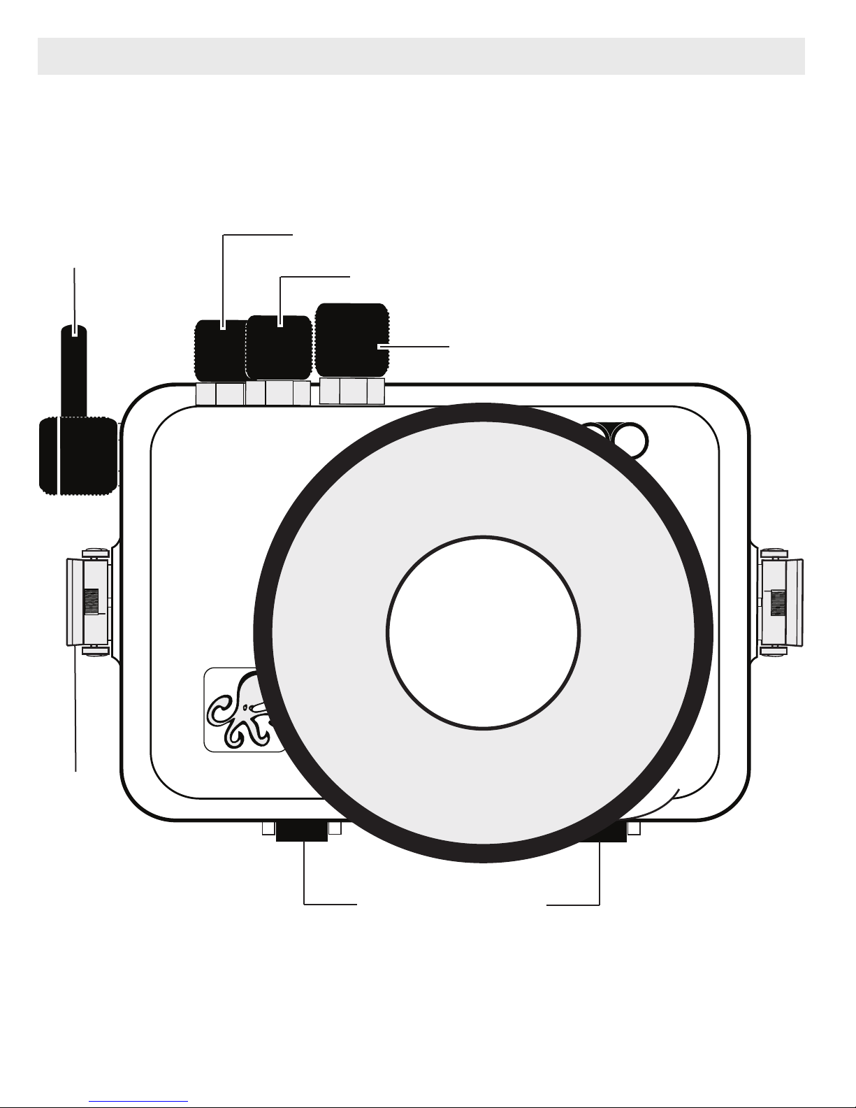
Parts of the Housing - Front View
Shutter
Release
Command Dial
Zoom Control
Mode Dial
Lens Port
Lid Snap
External Tray Mounts
5
Page 6
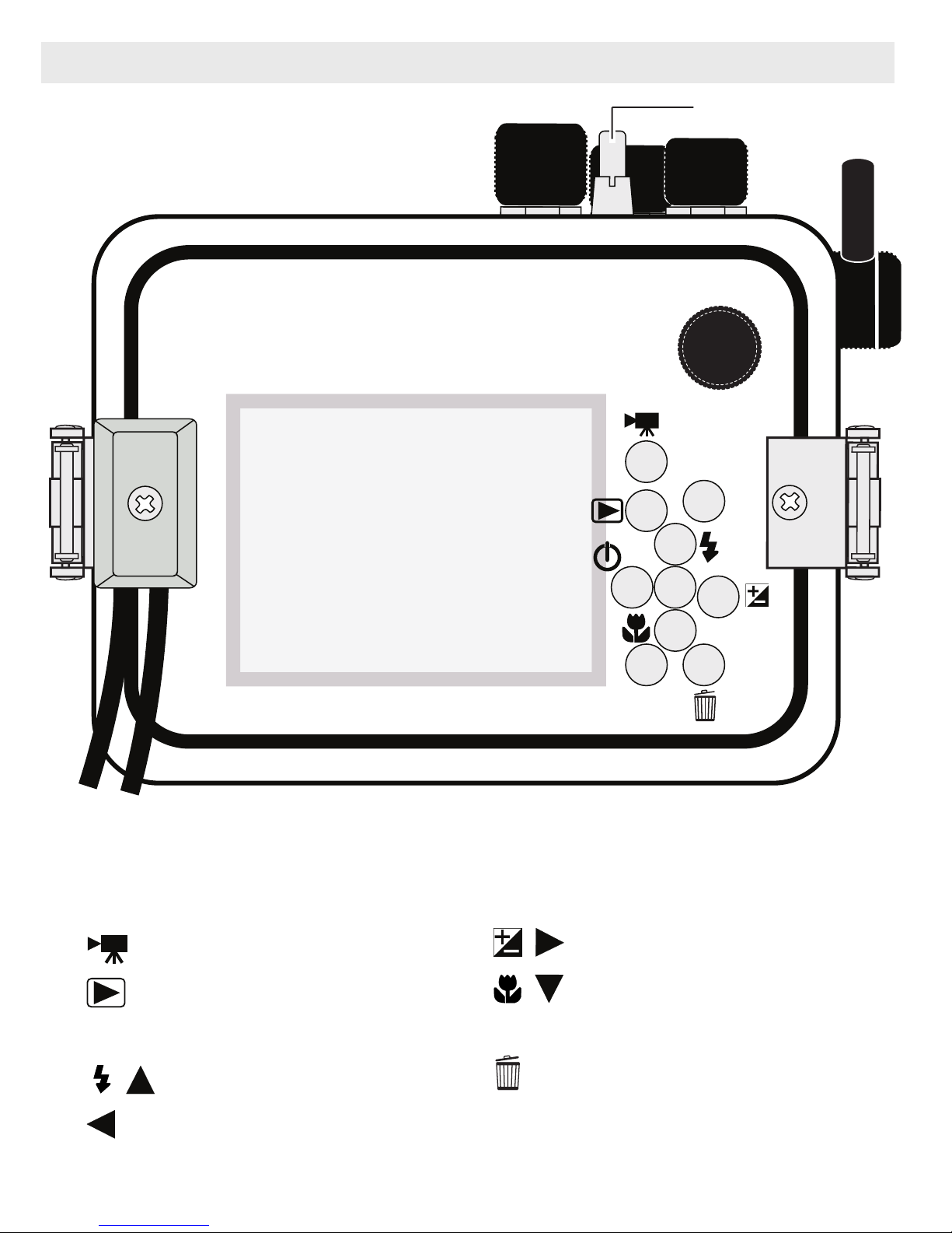
Parts of the Housing - Back View
6
5
3
8
7
9
11
4
MENU
2
10
WIFI
1
Power Switch
Housing Controls
1. Command Dial
2. Movie-record Button
3. Playback Button
4. Wi-Fi Button
5. Flash / Up Arrow
6. Self-timer / Left Arrow
6
7. OK Apply Selection Button
8. Exp. Comp. / Right Arrow
9. Macro Mode / Down Arrow
10. MENU Button
11. Delete Button
Page 7

Housing and Camera Setup
STEP 1 - Initial Camera Setup
Setup your camera for underwater use and then adjust your settings once underwater.
(before placing camera in housing)
Initial Camera Setup (before placing camera in housing)
- Remove camera lanyard if attached.
- Start each dive with a fully charged camera battery.
- Set Mode Dial to “M” Manual. Set shutter speed to 1/125th second and
aperture to F5.6 when using external strobes or F3.7 when using only
the built-in flash, page 12.
- In MENU - M:
Set Image Quality to “Fine” and Image Size to “16:9/12m.” NOTE: Other
Image Sizes can be used, however, slight vignetting may occur.
Set White balance to “Auto.” Always use AUTO white balance (AWB)
when using a strobe/flash. When recording video or using a UR-Pro
color filter without strobes, AWB can still be used, but for more accurate
and consistent colors we recommend setting Manual white balance.
Manual white balance should be reset for each working depth due to
color absorption caused by the water.
Set Metering to “Center-weighted” and Continuous to “S.”
Set ISO sensitivity to “200.” When using built-in flash only set to “800.”
Set AF area mode to “Center” and autofocus mode to AF-S “Single AF.”
- In MOVIE MENU - :
Set Movie Options to “1080/30p” and AF area mode to “Center.”
Set Autofocus mode to “AF-F” and Movie VR to “On.”
Set Frame Rate to “30 fps.”
Continued on Page 8 >
7
Page 8
STEP 1 - Initial Camera Setup
- continued
- In SETUP MENU - :
Set camera Time Zone and Date.
In Monitor Settings, set Image Review to “ON.”
Set Photo VR to “ON” and AF assist to “OFF.” Set Digital Zoom to “OFF.”
Set Auto Off to “5m.”
Insert and format a memory card.
- RAISE the FLASH! Set Flash to “Standard Flash.”
- Set Macro mode to “ON” when shooting close-up images. If the
image is overexposed, use “-” exposure compensation and/or back
away, zoom in, and then reshoot.
** All camera settings not listed should be set to the user’s preference.
Adjust settings once underwater to acco mmodate your shooting situation.
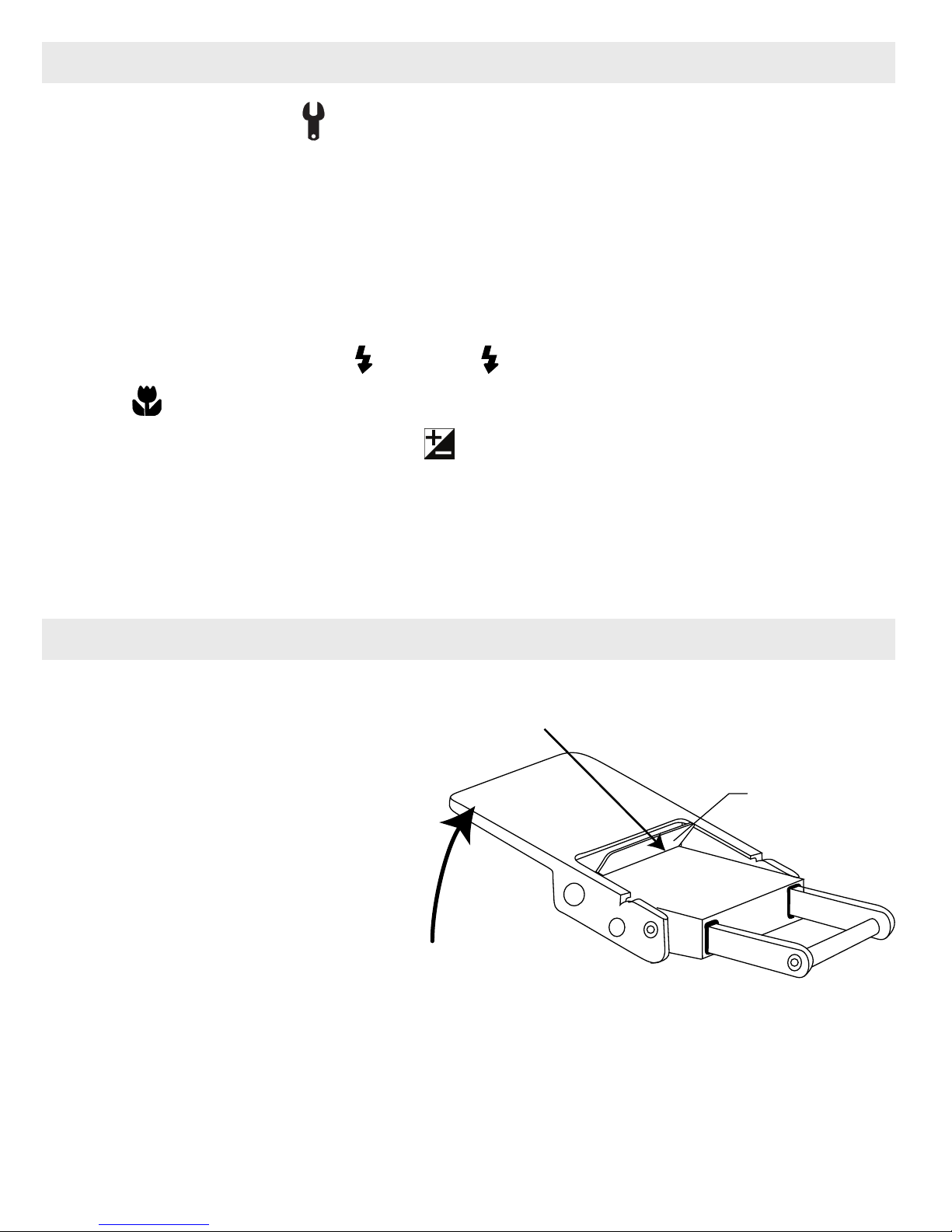
STEP 2 - Opening the Housing
Lid Snaps have a Lock.
1. Push Lid Snap Locks
forward and lift as shown.
Open opposing Lid Snaps
simultaneously. Keep
pressure on the Lid Snaps
so they do not fly open
quickly.
Some Lid Snaps have a lot
Lift
Push Forward
Lid
Snap
Lock
of spring tension once they
go over center, so keep a
firm grip on each Lid Snap.
Lid Snaps may also be opened one at a time.
2. Remove the Housing Back.
8
Page 9
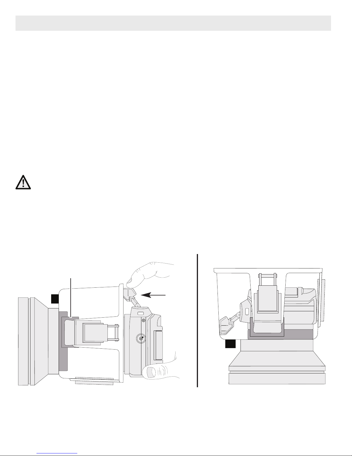
STEP 3 - Camera Installation/Removal
Installing Camera
1. Remove any lanyard attached to the camera.
2. Pull out on each housing control until it stops. This will get the controls
out of the way for installation of the camera.
3. Set the housing front on a table.
4. If not already done, raise the camera flash. Gently slide the camera into
the front mounting blocks while simultaneously pushing down slightly on
the camera flash, Diagram A.
4. While holding the camera in its seated position in the front mounting
blocks, rotate the housing front 90° so the port is resting against the
table top, Diagram B.
CAUTION: Camera is NOT secure in the housing until the housing back
has been installed.
5. See “Closing the Housing”, page 11.
Diagram A
Mounting Block
Diagram B
9
Page 10
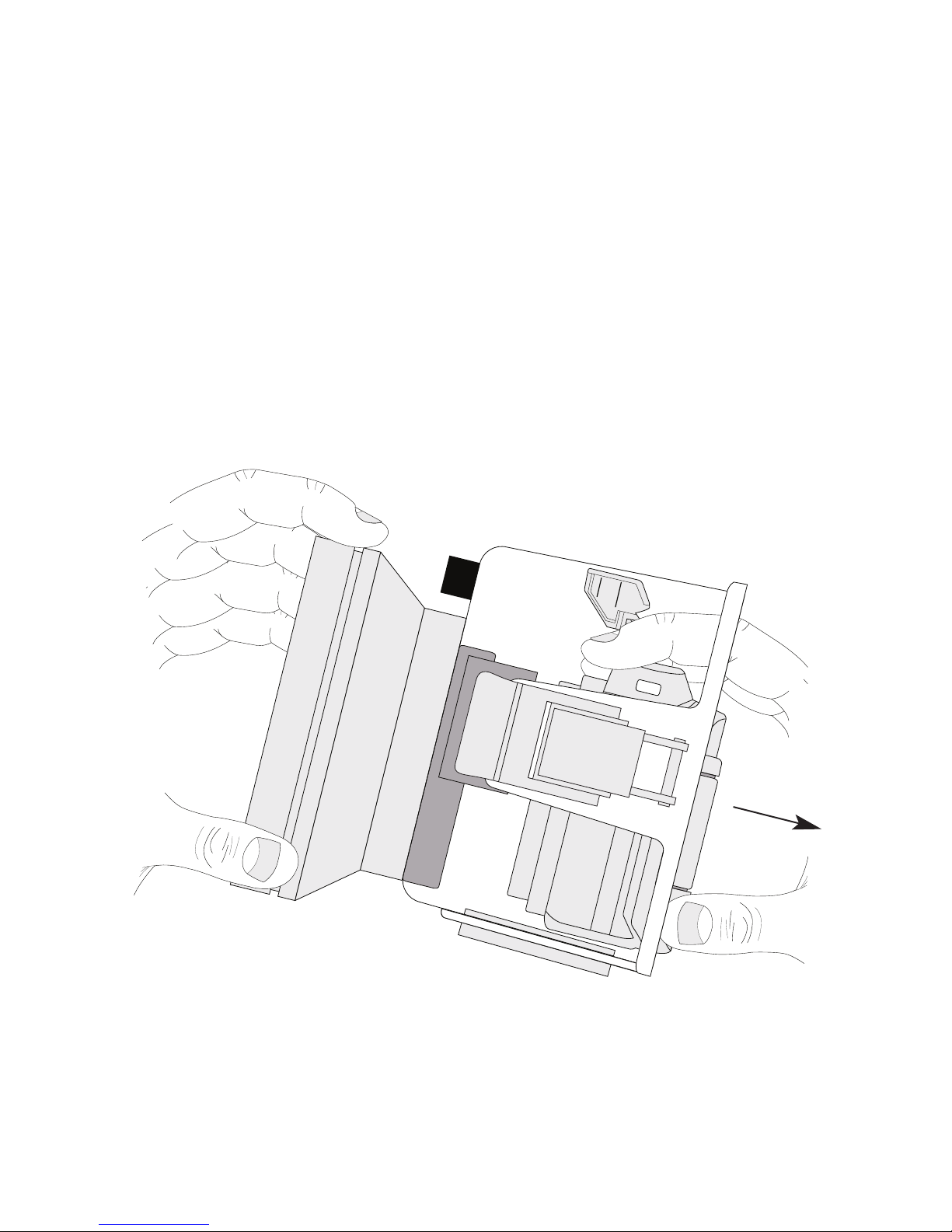
Removing Camera from Housing
1. Place housing face down on a table, Diagram B, page 9; remove
Housing Back and pull up on housing top control knobs.
2. Rotate housing 90°, Diagram A, page 9.
3. Tilt housing port up slightly with one hand while removing the camera
with your other hand, Diagram C, below.
Diagram C
10
Page 11

STEP 4 - Closing the Housing
1. Once the back is properly
installed, the o-ring should touch
the housing all the way around.
There should be an even gap on
each side of the housing between
the housing and the back.
2. Lift the lid snaps so they are
extended and place each lid snap
into the corresponding hook on
the housing back.
3. To close the housing, push down on
the opposing lid snaps simultaneously
until they snap into place. Be sure
they are down far enough to engage
Even gap on
all four sides
Lid Hook
Housing Back
Lid
Snap
Lid Snap Lock
O-ring
the Lid Snap Lock. The o-ring seal
should now appear as a solid black
line from the back of the housing.
STEP 5 - Final Check
The clear housing permits instant visual inspection of the camera and
sealing surfaces as well as complete monitoring of controls and camera
LCD screens. This housing has been factory water pressure tested to
200 ft (60 m).
Once the camera is properly installed and the housing is closed, recheck
the o-ring seal. Double check the gap between the housing back and the
housing. It should be even all the way around the housing.
Look through the clear plastic back at the o-ring. You should see a
darkened area or solid black line where the o-ring is compressed against
the housing back. If you do not see an even black compression seal all
the way around the back, open the lid snaps, reseat the housing back and
close the lid snaps. Visually check the seal again.
11
Page 12

Housing Usage
Turn the camera on and operate each of the housing controls to assure
proper functioning. Take a few test shots on land. Make sure the Flash
Diffuser is installed when using only the built-in camera flash, or install
the Flash Deflector when using external strobes, pages 13 and 14.
Zoom Control Use
After you have used the housing's
zoom control, it must be returned to the
center position to disengage. If the
h
ousing zoom control is pushing the
zoom lever in either direction, you may
-
+
-
not be able to take a picture or access
other functions. This is because the
camera is receiving a signal from the
engaged zoom control.
Zoom Control
“Disengaged”
(Center Position)
Zoom Control
“Engaged”
Using the Camera’s Built-in Flash
Initially set the camera lens to the widest angle setting. You may need to
zoom the lens slightly if a dark area appears in a lower corner of
close-up photographs. The lens port may block some of the light. Install
the Diffuser, page 14, and zoom in to eliminate any dark areas noted in
your photographs (You can test this above water). Set ISO to 800 and
aperture to F3.7 when using the built-in flash only.
+
For the best results, we recommend using external Strobes.
The camera’s built-in flash CANNOT be used with optional Wide Angle or
Accessory lenses.
Always remove the Deflector and install the Flash Diffuser when using
only the built-in flash, pages 13 and 14. Always install the Flash
Deflector when using external strobes, page 13.
12
Page 13

Strobe Use
The optional AF35 strobe triggers and provides automatic TTL exposure
by watching the camera's built-in flash, without the need of fiber optic
cords or sensors. Alternatively, two ports are provided on the front of the
housing for the connection of up to two Ikelite, SEA&SEA, or Olympus
type fiber optic cords.
An included flash diffuser improves lighting quality when the camera's
built-in flash is used. The built-in flash is effective between 1-3 feet
(0.3-0.9 m) from the subject in clear conditions. For best results, a color
correcting filter or external lighting is recommended. External lighting is
more powerful and can be placed in a position to virtually eliminate the
backscatter or "snow" from your underwater images.
Always install the Flash Deflector when using external strobes, page 13.
Deflector Installation and Removal
The factory installed flash Deflector should be removed and replaced by
the Diffuser, page 14, when using ONLY the built-in camera flash and no
external strobes. To remove, lift the bottom of the Deflector with your
thumb, or a Pen or Pencil tip to loosen and pull the Deflector away from
the inside front of the housing. To install, line up the corresponding
Velcro dots on the housing front with the Deflector Back and press the
Deflector into its factory installed position next to the lens port. If
positioned properly, the small deflector holes will line up with the Fiber
Optic Port holes.
Deflector Front (view from inside housing)
Deflector Hole Velcro
Deflector Back (view from outside housing)
13
Page 14

Diffuser Purpose
When using the built-in camera flash and shooting close-up photographs,
the lens port on the housing can block a portion of the light from the
built-in camera flash. This can result in a shadow in a lower corner of the
picture frame. The Diffuser will help eliminate the shadow. In addition,
you can zoom in if necessary.
Diffuser Installation and Removal
The included Diffuser should only be used when shooting with the
built-in camera flash. A
lways remove the Deflector before using ONLY
the built-in camera flash with a Diffuser.
To install the diffuser, push the “Cut-out Section” into the Port Groove
until it stops as shown. To remove, grab the top of the Diffuser and pull
away from the port.
Note the Small Hole. To avoid losing the diffuser, you can attach a
fishing line or string to this hole.
Diffuser
Cut-out
Section
Small hole
14
Diffuser properly
installed in Port Groove
Page 15

Entering the Water
MADE IN USA
As soon as you enter the water, take a moment and check to see that
the housing is properly sealed. We recommend you first water test the
housing with no camera inside to assure a safe and watertight
environment.
Next, check to see if there are any bubbles on the face of the lens port.
If there are, take your finger and remove them. If there are bubbles on
the lens port they can produce soft focus spots in your photos or video.
Recommended Accessories
External Color Correcting Filters
The specially formulated UR/Pro color
correcting filter 6441.46 for tropical blue water
UR-Pro Filter
Lens Port
settings enhances warm reds and oranges with
available sunlight up to 80 ft (24 m). Use in the
Caribbean, Indonesia, and any blue water
setting.
The UR/Pro color correcting filter 6441.86 for
green water enhances contrast and improves
the color of green water to give your subject a
rich, natural tone. Effective with available
sunlight up to 80 ft (24 m). Use in most lakes and any green water
setting. The color filters are for available light use only.
Not recommended when using external strobes.
Optional Tray with Release Handle 9523.63
The optional aluminum tray with release
handle comes with the necessary hardware to
mount to your Ikelite housing. To attach, see
page 16.
15
Page 16

Optional Tray + Dual Handles
MADE IN USA
Attaching an optional Tray + Dual Handles will
add stability and gripping point(s) for
comfortable use of the housing. Add a second
strobe to eliminate shadows and evenly light
your subjects.
Attach Optional Tray + Release Handle(s) to Housing
1. Place the housing upside
down on a flat surface or in
your lap so that the housing
MADE IN USA
port is facing toward you as
shown.
2. Line up the 3/8” tray holes
with the housing mounts. If
the tray is positioned
properly, the handle will be
n your left side facing down.
o
3. Place a shoulder washer in
each 3/8” tray hole with the
small end of the washer
facing down.
4. With your free hand, insert and rotate the 1/4-20 x 1/2” screws clockwise
until threaded into the housing mounts. Finish tightening the tray to the
housing using a flathead screwdriver. Do not overtighten.
16
Page 17

Attach Optional Strobe Arm to Housing Handle
If you have purchased an optional
Ikelite Tray and Handle for your
housing, an Ikelite Strobe Arm will
easily attach to the Handle by
depressing the spring-loaded Handle
Push Button until it stops. Gently slide
the pronged end of the Ikelite Arm into
the hole in the top of the Handle as
Ikelite Arm
shown.
When the Ikelite Arm is properly
seated, the Handle Push Button will
return to it’s starting position.
AF35 Strobe Package 4035
The AutoFlash AF35 kit is a great
compliment, and an effortless, affordable way
to add a flash to your new Ikelite point and
shoot camera system. Everything you need
to get started is in the box. Just attach it to
Housing Handle
ndle P
Ha
Button
ush
ikelite
AUTOFLASH
ikelite
35
AF
the bottom of your housing and start taking
pictures!
The AF35 Strobe Package is available to support your housing along
with a full range of accessories. Please visit ikelite.com to see additional
i
nformation regarding this and other strobe package options.
17
Page 18

External Accessory Lenses
WD-4 Wide-Angle Conversion Dome 6430.4
The removeable WD-4 corrects light refraction underwater,
restoring the camera’s original angle of coverage. Approximately
3/4 of the camera's zoom range can be used with the dome in
place. Slight vignetting may occur at camera’s widest angle setting.
External Macro Adaptor 9306.82
Allows attachment of 67mm threaded macro lenses from Inon and
Epoque. NOT for use with 67mm threaded wide-angle lenses.
Notes: Other than the 6430.4 and 9306.82, no other accessory lenses
or adaptors can be used with this housing.
The camera’s built-in flash cannot be used with External Accessory
Lenses.
Recommended Accessories -
continued
Video Lighting
External video lights such as the 2101 Vega Video + Photo Light add
color when using the video/movie mode of your camera. Primary video
lights are specially color balanced to provide natural tones.
- 2602.3 Quick Release Handle Kit for GoPro
- Gamma LED Focus/Flashlight
A full range of accessories are available to support your housing. Please
visit ikelite.com to see the most current information about recommended
accessories for your housing.
18
Page 19

Maintenance
Lens Port
Treat the glass in the lens port as a camera lens. After use, rinse and
gently dry the outside lens port to avoid water spotting. To clean, use a
mild soap solution or lens cleaner. It is N
Port for cleaning. Do not rinse the inside the Port.
Do not use alcohol or window cleaner on the Lens Port.
OT necessary to remove the
Lubricant
Ikelite provides silicone lubricant with the housing. We recommend you use
only Ikelite lubricant on Ikelite products. Other brands may cause the main
housing o-ring to swell and not seal properly.
Use only enough lubricant to lightly cover the main housing o-ring or
lubricate a sticky control. Wipe off any excess lubricant with a clean
cloth. Lubricant is not a sealant; it is used to reduce friction. Excessive
lubricant can collect sand and dirt which may interfere with proper
sealing.
CAUTION:
Never use spray lubricants as the propellant ingredient can cause
the plastic housing to crack or o-rings to swell.
O-ring Storage
When storing the housing, remove the main housing o-ring. Lightly
lubricate the o-ring until it appears shiny and place in a small resealable
plastic bag. Use only Ikelite lubricant. Place the bag inside the housing
and store until needed.
19
Page 20

Housing Maintenance
Your Ikelite Digital Housing should be given the same care and attention
as your other photographic equipment. In addition to normal
maintenance, we recommend that the housing be returned to Ikelite
periodically to be checked and pressure tested.
- Do Not leave the camera and housing in direct sunlight for prolonged
periods. Heat may damage the camera.
- Do Not ship the camera in the housing.
- Before using the housing, always check the tightness of the set screw in
each control knob. Check each control gland penetrating the housing to
make sure they are tight. There is a slight chance that either could
vibrate loose during travel.
- Keep the main housing o-ring clean and lightly lubricated. To lubricate,
remove the o-ring from the back. Put a small amount of lkelite lubricant
on your fingers. Pull the o-ring through your fingers to apply a thin
coating of lubricant. Only apply enough lubricant to make the o-ring feel
slick. Do Not stretch the o-ring. This light coating of lubricant will help
to keep the o-ring from drying out and will help to show a dark sealing
line when the housing back is properly sealed.
- Keep the area where the o-ring fits and the sealing surface of the
housing clean.
- Rinse the housing exterior thoroughly in fresh water after each saltwater
use. Depress push buttons repeatedly in fresh water to eliminate trapped
saltwater. Dry with a soft cloth. Dry lens port to eliminate water spotting.
After several uses in saltwater, soak the housing exterior in a mild soap
solution; rinse and dry before storing. When storing the housing, remove
the back o-ring, lightly lubricate, and place in a plastic bag. Place the
plastic bag with o-ring inside the housing for safe keeping.
- If removing a housing push button, Do Not re-use the E-clip. Contact
Ikelite for replacement E-clips (part 0319.12).
- Leave lid snaps in the open position when not using the housing for
extended periods.
20
Page 21

Control Maintenance
Ikelite controls are designed to provide years of reliable service with
minimal maintenance.
- Push button controls normally require no maintenance other than rinsing
in freshwater after saltwater use. Depress each push button in fresh
water several times to eliminate trapped saltwater. If a push button
control becomes difficult to push or if it sticks when depressed, soak the
housing in luke warm fresh water. After a few minutes, operate the push
button. If this does not correct the problem, return the housing to Ikelite
for maintenance. If you are on a trip and unable to return the housing
immediately, a push button may be lubricated by pressing and holding
the push button all the way in. Then, use your finger or other small
non-metal object to place a small amount of lube at the base of the shaft
inside the housing. Press and release the push button several times until
the lube is worked up into the o-ring.
After completing this procedure, close
the housing and submerge it in water
without the camera i nside. Check the
control for watertightness.
Diagram D
Apply Ikelite Lube here
21
Page 22

Control Maintenance -
continued
- Some of the controls have long shafts and feature a hex style control
gland. These controls can be pulled out, exposing the shaft, Diagram E,
page 23.
To lubricate the control, gently pull on the knob until the stainless steel
shaft is exposed. Lightly lubricate the shaft, then move the shaft in and
out several times. This will lubricate the x-ring in the Ikelite control g
This should be done before using the housing after a prolonged storage
period, or once a week when the housing is in constant use.
- Some of the controls have a short shaft and cannot be pulled out
exposing the shaft for lubrication. In the unlikely event one of these
controls sticks or becomes difficult to operate you can remove the
control from the housing and lubricate it, or return the housing to Ikelite
for maintenance. To remove the control, Diagram F, page 23, loosen
the set screw in the knob (allen wrench required); remove the knob. If
there is salt or dirt build-up on the exposed control shaft, clean the shaft.
Open the housing and gently slide the control shaft out of the control
gland. Clean and lightly lubricate the shaft, including the end of the
shaft. Slide the shaft back into the control gland and gently slide the
shaft back and forth a few times without fully removing the shaft from the
land.
gland. Replace the knob noting the flat area on the shaft. The set screw
in the knob should tighten down against the flat area on the control, so
the knob does not turn on the shaft.
Close housing without a camera inside and water pressure test in a
bathtub or swimming pool. Rotate* the knobs to make sure the housing
is watertight and the gland was installed properly. Check all controls
while the housing is submerged.
*Caution: If your housing has a shutter spring, DO NOT rotate the
shutter control more than 1/16th of a rotation, otherwise, you may
accidentally bend the shutter spring or cause the spring to “pop off” the
control shaft.
22
Page 23

Control Maintenance -
continued
Slide the shaft back into the control gland and gently slide it back and
forth a few times without fully removing the shaft from the gland.
Replace the knob, noting the flat area on the shaft. The set screw in the
knob should tighten down against the flat area on the control so the
knob does not turn on the shaft.
After completing this procedure, close the housing and submerge it in
water without the camera inside. Check the control for watertightness.
Diagram E
Housing
Diagram F
Tighten set screw down
when replacing the knob.
Lubricate shaft
Pull out knob to
expose shaft
Control
Gland
Loosen set screw
(allen wrench required)
against this flat area
Control
Shaft
Lubricate end of shaft
before reinserting into
gland
Housing
23
Page 24

Photo Tips
- The number one rule in underwater photography is to eliminate as much
water between the camera and subject as possible. Get as close as you
can to the subject, then use the zoom. If you are using flash for still
photos, subjects beyond 6 feet (1.8m) will not have much color
regardless of strobe power.
- Photograph in clear water; do not stir up the sand or silty bottom. If
backscatter becomes a problem in the environment you are
photographing, an external flash will help eliminate much of the
backscatter.
- Many digital cameras have a slight lag time between when you press
the shutter release button and the camera actually takes the picture.
Hold the housing steady a second or two after pressing the shutter
release button.
- Do not shoot down on subjects as they will quite often blend into the
background and be difficult to see in the photograph. Shoot subjects
straight on or shoot up at a slight angle using the blue water as a
contrasting background. Do not shoot into the sun.
- When using daylight or flash, if your camera consistently over or
underexposes the image, you may want to adjust your camera’s
exposure compensation settings.
- If you error in exposure, it is better to have the image slightly
underexposed rather than overexposed. An overexposed image is
missing color information which cannot be adjusted in a photo
processing program. A slightly underexposed image has color
information that can be adjusted.
- It is important to respect all living creatures underwater, including
people, marine life, and coral. While we encourage people to get close
to their subjects when taking a photograph, they should not touch, lie on,
or in any way disturb the things they find underwater.
24
Page 25

Troubleshooting
Problem
Push buttons or
controls are sticky or
hard to operate
Solution
- Remove the camera and rinse the closed housing
in fresh water. Vigorously press each push button
in and out several times to release any trapped
saltwater or debris.
- Press a sticky push button all the way in and
place a small amount of lube on the small end of
the push button shaft at it’s base. Release and
operate the push button several times to distribute
the lube, Diagram D, page 21.
- If a larger gland style control is sticky, grab the
control knob, pull it out, and then push back in. If
still sticky, see the Control Maintenance section,
Image is
over/underexposed,
or a corner of the
image is dark
pages 22-24.
- Return housing to Ikelite for routine maintenance.
- Check that the built-in flash or external strobe is
firing when taking a picture. Camera flash should
be forced “on.”
- When using an external strobe, make sure it is
turned on, set properly, and its battery is charged.
- Make sure the diffuser is installed when you are
NOT using an external strobe.
- Check any corded connectio
- Change camera shutter speed or aperture.
- Move closer to or further away from the subject.
- Adjust Exposure Compensation .
n p
oints.
- If using a strobe, check deflector Fiber Optic hole
alignment with Fiber Optic Ports.
25
Page 26

Problem
Solution
Camera does not
take a picture
Housing is hard to
close
- Install a fully charged battery.
- There is not enough available light for the camera
to properly focus. Add a focusing light or strobe
with a built-in focusing or video light to your
system.
- Select a center focus point in your camera menu.
- Return Zoom control to the “disengaged” position,
see Zoom Control Use, page 12.
- Make sure the camera is mounted properly in the
housing and controls are out of the way.
- Main housing o-ring i
s not seated properly.
Fogging occurs on
the Lens Port
- Humid air is trapped inside the housing.
The camera produces heat and may condense
any trapped moisture forming fog on the lens port.
Close the housing in an air-conditioned room or
vehicle, or in front of an air-conditioner.
- The housing should not be in direct sunlight for an
extended period of time.
- Purchase desiccant packs also known as
moisture munchers from a local camera store.
Place one or two new packs in your housing
before each day of diving.
- If moisture or water droplets are present around
the controls or sealing areas, return the housing
to Ikelite for evaluation.
- Clean the main housing o-ring and sealing
surface of the housing.
26
Page 27

Problem
Solution
Water enters the
housing
Pictures are too blue
or too green
- Remove, clean and properly lubricate the main
o-ring.
- Look for hair, dirt, or foreign debris crossing the
o-ring seal.
- Reassemble the housing without a camera
installed and immerse in water.
- Return housing to Ikelite for evaluation.
- Use custom (manual) white balance. Reset for
each working depth or when attaching a
color correcting filter to the camera lens.
- Add an external strobe.
- Move in closer to your subject when taking a
picture.
- Add an optional color correcting filter to the
Housing Port.
- Strobe is not firing. Check corded connection
points. Check deflector Fiber Optic hole alignment
with Fiber Optic Ports.
27
Page 28

Spare Parts
- 0132.30 Port o-ring
- 0200.08 Port cover
- 0184.2 Silicone Lubricant 2cc Reclosable Tube
- 0109 Main o-ring
- 9523.10 Tray Hardware
(available through Ikelite or any Ikelite Dealer)
28
Page 29

Customer Support
Please read the troubleshooting section of this instruction manual before
contacting Ikelite Customer Support.
Ikelite Underwater Systems
Service Department
50 West 33rd St.
Indianapolis, IN 46208 USA
Email: ikelite@ikelite.com
Phone: 317-923-4523
29
Page 30

Limited Warranty
This Ikelite product is warranted against any manufacturing defects for a
period of one (1) year from the original date of purchase. Defective
products should be returned to Ikelite postage paid. Ikelite will, at its sole
discretion, repair or replace such products, and will return to customer
postage paid. All other claims of any nature are not covered. Except as
mentioned above, no other warranty expressed or implied applies to this
Ikelite product.
30
Page 31

Returning Products For Service
Ikelite is most interested in performing any service to ensure that all
products perform as intended. Evidence of purchase date must be
provided to obtain warranty service.
No prior authorization is required. You may return directly to us or
through your dealer. Please include a brief description of the problem,
any relevant email correspondence, and/or instructions on what you
want us to do. Always include name, shipping address, email address,
and phone number inside of the package. Send postage paid to:
Ikelite Underwater Systems
Attention: Service Department
50 West 33 Street
Indianapolis, IN 46208 USA
No reimbursements for postage paid will be issued.
You may also want to insure the package.
Returning Products for Service -
For the separate international customs documentation form that you
complete to accompany the shipment, please state or designate that the
enclosed products were originally manufactured in the USA and are
being returned to the manufacturer for repair service. Value of the
equipment listed for customs purposes should be zero.
outside the United States
31
Page 32

Product Registration
Please go to ikelite.com to register your Ikelite housing within 15 days
of purchase.
Ikelite Underwater Systems
50 West 33rd Street
Indianapolis, IN 46208 USA
ikelite.com
© 2015 Ikelite Underwater Systems
6184.99_Nikon_S9900_02-0715
 Loading...