

Ikelite 6182.78, 6182.78 Nikon P7800 Instruction Manual

6 182.78
Underwater TTL Housing for
Nikon P7800
Instruction Manual
Thank you for your purchase of Ikelite equipment. Please read this
instruction manual completely before attempting to operate or dive
with this product. Please refer to the back page of this manual to
register your Ikelite product.
Table of Contents
Package Contents ........................................................P. 3
Specifications ..............................................................P. 3
Attach Tray and Handle to the Housing ..........................P. 4
Preparation ..................................................................P. 5
Initial Camera Setup........................................................P. 5
Housing Controls - Front View ........................................P. 7
Housing Controls - Back View ........................................P. 8
Opening the Housing ......................................................P. 9
Installing the Camera ......................................................P. 9
Attach Hotshoe to Camera ..............................................P. 9, 10
Attach Camera to Mounting Tray ....................................P. 9, 10
Using the Camera’s Built-in Flash ..................................P. 11
Closing the Housing ........................................................P. 11
Usage ............................................................................P. 12
Final Check ....................................................................P. 12
Zoom Control ..................................................................P. 12
Diffuser and Deflector Installation and Use ....................P. 13
Conversion Circuitry ........................................................P. 14
Attaching an Ikelite Strobe Arm to the Housing Handle..P. 14
Attaching a Sync Cord to the Housing ............................P. 15
Turn Camera On..............................................................P. 15
Entering the Water ..........................................................P. 16
Maintenance ................................................................P. 16
Lens Port ........................................................................P. 16
2
Table of Contents
Lubricant..........................................................................P. 16
Housing Maintenance......................................................P. 17
Control Maintenance ......................................................P. 18
Photo Tips ..................................................................P. 20
Troubleshooting ........................................................P. 20
Spare Parts ..................................................................P. 24
Recommended Accessories ....................................P. 24
Customer Support ......................................................P. 26
Limited Warranty ........................................................P. 26
Returning Products for Service ................................P. 27
- continued
Product Registration ..................................................Back Cover
Package Contents
- 6146.16 Ikelite Digital Housing
- 9523.61 Tray with Single Handle
- 0200.08 Vinyl Port Cover
- 0184.1 Silicone Lubricant
- Flash Diffuser
- Flash Deflector
- Extra Control Tips
Specifications
Width ......................7.5 in (190 mm) including controls
Height ....................6.2 in (157 mm) including controls
Depth ......................6.4 in (163 mm) including controls and lens port
Weight ....................4.5 lb (2 kg) above water
Buoyancy ................Slightly negative in saltwater for stability
3
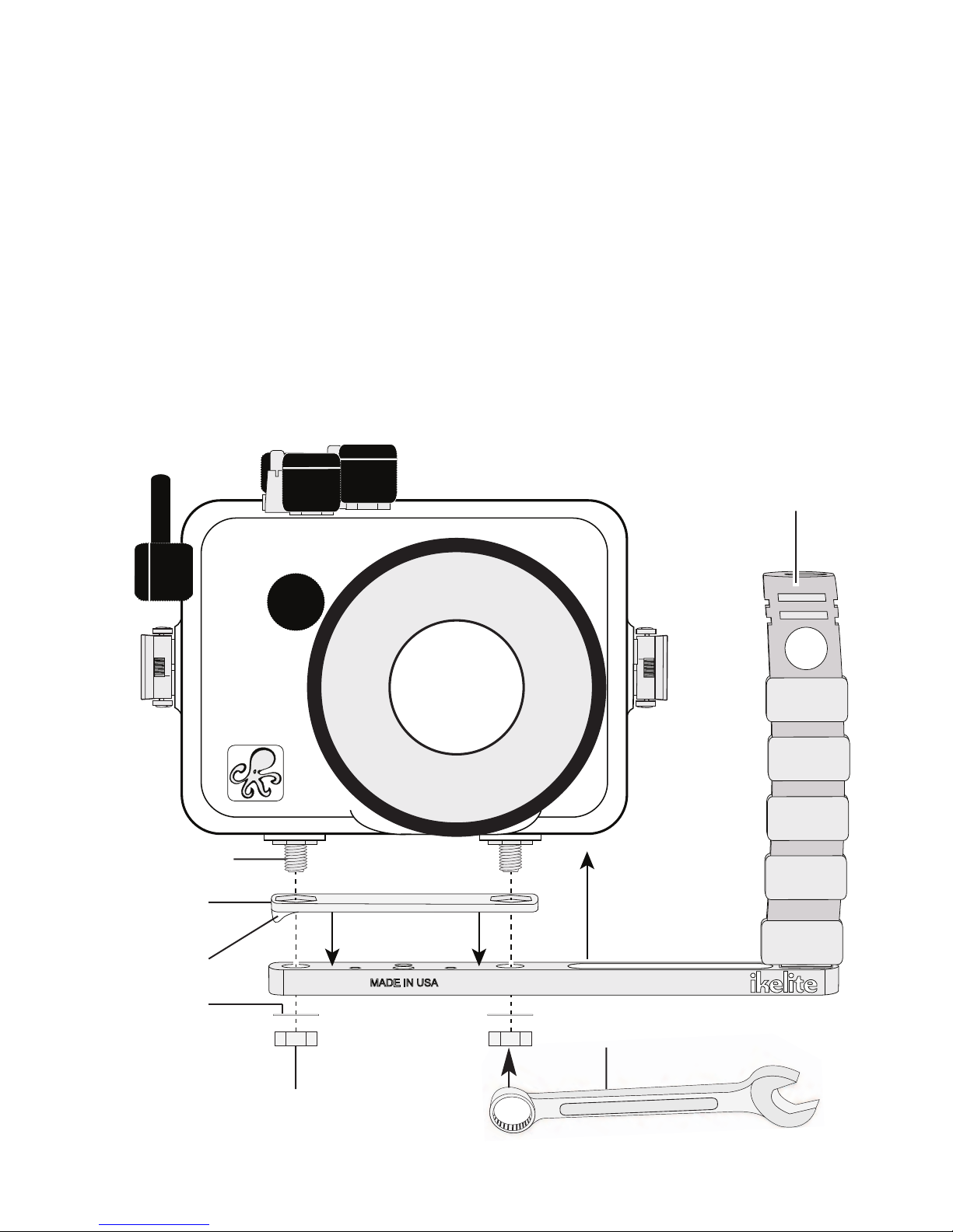
Attach Tray and Handle to the Housing
Using a 9/16” open/box end or socket Wrench (not supplied), firmly
tighten the External Tray and Spacer to the Housing Base using the two
3/8-16 Nuts and Washers supplied in the accessory package. One side
of the Spacer has an adhesive backing. Remove the Protective Film to
adhere the Spacer to the Tray.
Note: Tray and Handle may be attached before or after the camera is
secured in the Housing. We recommend attaching it immediately to avoid
scratching table tops with the Tray Mounting Bolts.
External Tray
& Handle
Tray Mounting Bolt
Spacer
Protective Film
Washer
3/8-16 Nut
4
MADE IN USA
Wrench - not supplied

Preparation
This product has been water pressure tested at the factory and is depth
rated to 200ft (60m). Thoroughly inspect and immerse the empty
housing completely in water before installing a camera. If any fogging
occurs or droplets of water enter the housing, do not install a camera.
Clean the main housing o-ring and retest to make sure that it is
watertight. Refer to the Troubleshooting section, page 21.
Please read your camera manual thoroughly to have a full
understanding of each camera function.
If you are new to underwater photography, be sure to read the Photo
Tips section, page 20.
Initial Camera Setup (before placing camera in housing)
- Insert a fully charged battery
- Set Shooting Mode dial to “A” Aperture priority or “M” Manual. In “A”
Aperture Priority mode the shutter speed will lock at 1/30th second. If a
faster shutter speed is desired or picture blur occurs, use “M” Manual
mode. For Macro photography, set Aperture to f8 and engage “Macro
close-up” setting in the camera menu.
- In the Set up Menu:
Set Time zone and date.
Set Vibration reduction to “On.”
Set AF assist and Digital zoom to “Off.”
Set Auto off to “5m” 5 min.
Insert and Format an SDHC memory card.
Set Flash control to “Auto.”
5

Initial Camera Setup (before placing camera in housing)
- In the Shooting Menu:
Set Metering to “Center-weighted.”
Set Continuous Mode to “S” Single.
Set AF area mode to “Center (normal).”
Set Autofocus mode to (AF-S) “Single AF.”
Set Flash exp. comp. to “0.0.”
Set Noise reduction filter to NR “Normal.”
Set Built-in ND filter to “OFF.”
Set Distortion Control and Active D-Lighting to “OFF.”
Set Startup zoom position to “28” and Focus-coupled metering to “ON.”
- In Commander mode:
Set Flash Mode to “Standard flash.”
Set Flash control mode to “TTL.”
- In Quick Menu Settings:
Set Image Quality to “FINE” and Image Size to “12m.”
Set ISO to “200.”
Set Image Size to “12m.”
Set WB White Balance to “Auto (normal): AUTO1.” For best results, set
manual white balance for each working depth.
- Set Dial to “0.”
-RAISE the Flash. Flash CANNOT be raised once the housing is closed.
Flash is disabled in Continuous Shooting and Auto Bracketing modes.
6
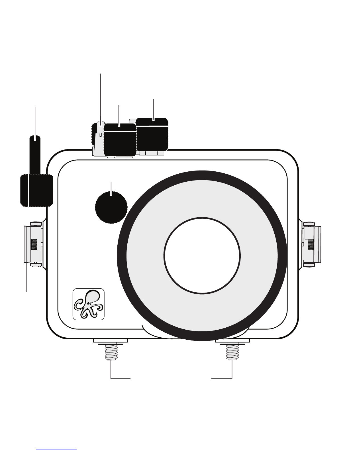
Housing Controls - Front View
All camera functions are accessed through the housing except for the Fn1
button and Flash pop-up control.
Fn2 Button
Shutter
Release
Zoom
Control
Sub-command
Dial
Mode
Dial
Lid
Snap
Lens Port
External Tray Mounts
7

4
5
7
8
9
10
3
11
12
13
1
6
2
Housing Controls - Back View
Power Switch/Power-on Lamp
Dial
Housing Controls
1. External Strobe Connector / Cap
2. Quick Menu Button
3. Main Command Dial
4. (AE-L/AF-L) Button
5. Playback Button
6. Rotary multi-selector (Note that a
small section of the rubber disc
is missing at the end of this control.
This is normal and allows the user
to completely disengage the control
from the camera when not in use).
8
Rotate the Rotary multi-selector to
the 12 o’clock position to disengage
control from camera dial.
7. Up / Flash Mode
8. Self-timer
9. “OK” Apply Selection Button
10. Right / AF Area Mode,
11. Down / Focus / Macro
12. MENU Button
13. Delete Button

Opening the Housing
Lid Snaps have a Lock.
Push Forward
To open housing, push Lid Snap
Lid Snap Lock
Lock forward and lift as shown.
Keep pressure on the Lid Snap so it
does not fly open quickly.
Some Lid Snaps have a lot of
Lift
spring tension once they go over
center, so keep a firm grip on the Lid Snap.
Lid Snaps may be opened one at a time.
Installing the Camera
1. Pull out on each housing control until it stops. This will get the controls
out of the way for installation of the camera.
2. Remove the back from the housing.
3. Remove camera lanyard from camera if attached.
4. The mounting tray for the camera is secured to the housing back.
Position the camera on the tray.
5. Attach Hotshoe to Camera by sliding the housing Hotshoe Connector
into the Camera Hotshoe Mount, diagram A, page 10.
Slide the
connector forward until it stops. This must be done before the camera is
secured with the mounting bolt, diagram B, page 10.
It is ok to leave the housing hotshoe connected to the camera even when
the External Strobe Connector is not being used.
6. Attach Camera to Mounting Tray by using a coin or screwdriver
(preferred). Secure the camera with the Tray Mounting Bolt which
threads into the camera’s tripod socket, diagram B, page 10.
7. RAISE the camera flash even if you intend to use ONLY hardwired
external strobes. The flash CANNOT be raised or lowered once the
housing is closed.
9
 Loading...