

Page 1

Digital Housing
instruction manual
for
Olympus
SP-350
Housing
#6132.35
Page 2
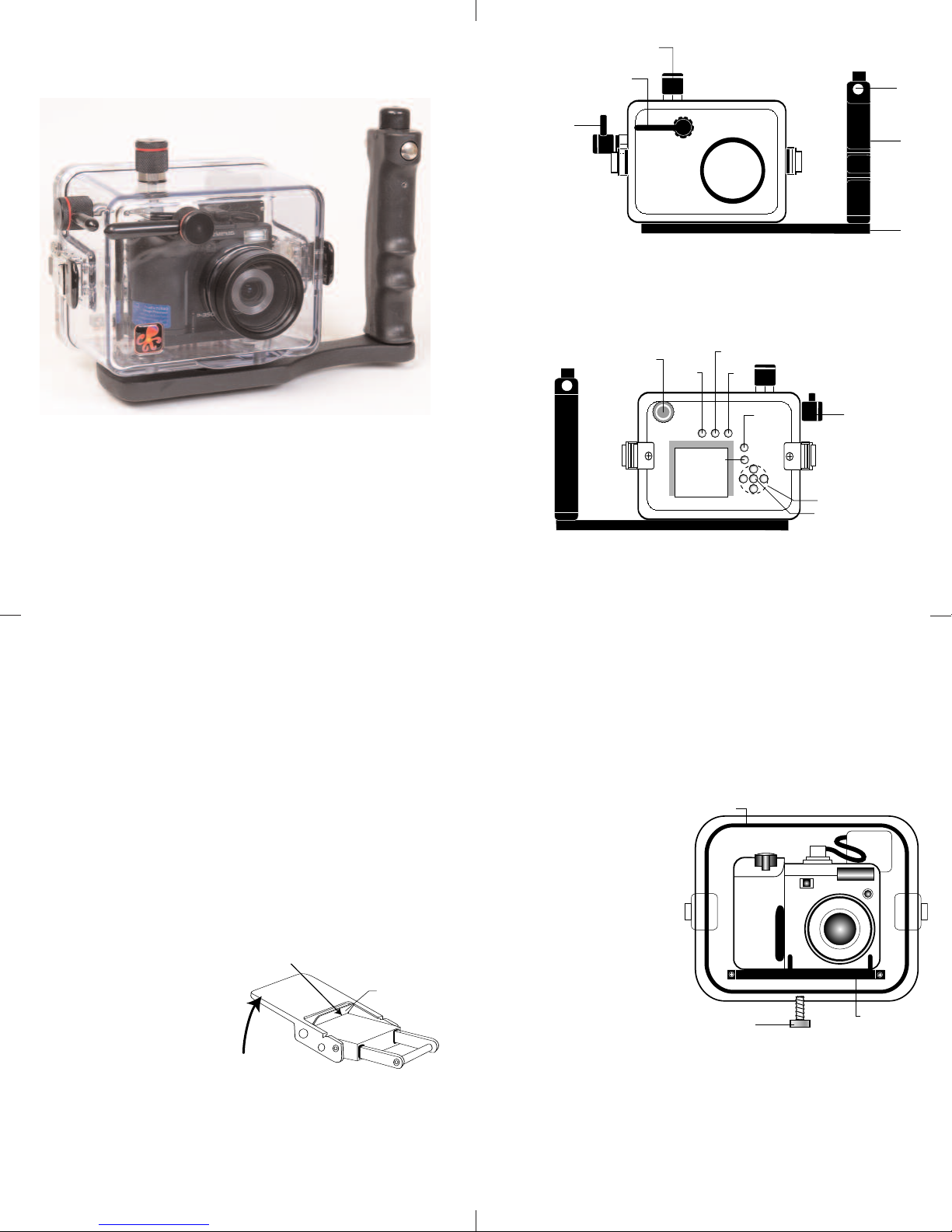
Ikelite Digital Housing
Shutter
R
elease
Disp/
Guide
OK/Menu
Power
Flash/Erase
AEL
Arrow Pa d
Shutter
R
elease
Lid
Snap
Lid
Snap
M
ode
Z
oom
T
ray
P
ush
Button
R
ubber
Handle
FRONT VIEW
BACK VIEW
External TTL
Strobe Connection
Lens Po r t
Quick View
Lift
Push For ward
Lid Snap Lock
Mounting
Bolt
Mounting
Tray
O'Ring
OLYMPUS
instruction manual
#6132.35 for Olympus SP-350
Congratulations on your purchase of an Ikelite Digital Camera
Housing. Ikelite has over 30 years of experience in the underwater
photographic and lighting market. Our products are designed and
built in the USA by Ikelite for both the professional and amateur
photographer.
The clear housing permits instant visual inspection of the camera
and all sealing surfaces as well as complete monitoring of controls
and camera LCD screens.
Ikelite Digital Housings are slightly negative in salt water for
stability. This housing has been water pressure tested at the
factory. Housing is pressure tested to 200’ (60m).
2
LLuubbrriiccaanntts
s
1. Ikelite provides silicone lubricant with the housing. We recommend
you use only Ikelite lubricant on Ikelite products as some other
brands may cause the o’ring to swell and not seal properly.
N
.
2. Use only enough lubricant to lightly cover control shafts and
o’rings. Wipe off any excess lubricant with a clean cloth.
Lubricant is not a sealant, it is used to reduce friction. Excessive
lubricant can collect sand and dirt which may interfere with
proper sealing.
CCAAUUTTIIOON
NNeevveerr uussee sspprraayy lluubbrriiccaannttss aass tthhee pprrooppeellllaanntt iinnggrreeddiieenntt ccaan
ccaauussee tthhee ppllaassttiicc hhoouussiinngg ttoo ccrraacckk.
OOppeenniinngg tthhee HHoouussiinng
1. Lid Snaps have a
To open, push Lid Snap Lock
forward and lift as shown.
Keep pressure on the Lid
Snap so it does not fly open
quickly.
Some lid snaps have a lot of
spring tension once they go over center, have a firm grip on the
lid snap. Lid Snaps may be opened one at a time.
LLoocck
g
k
.
3
IInnssttaalllliinngg tthhee CCaammeerra
a
Remove the back from the housing. The mounting tray for the
camera is secured to the housing back. Position the camera on
the tray and secure it with the mounting bolt which threads
into the camera’s tripod socket.
UUssee aa ccooiinn oorr ffllaatt bbllaaddddeed
ssccrreewwddrriivveerr ttoo ttiigghhtteenn tthhee mmoouunnttiinngg bboolltt ssoo tthhee ccaammeerraa iiss ffllaat
aaggaaiinnsstt tthhee ttrraayy.
CCAAUUTTIIOONN:
:
.
d
t
Some camera tripod
socket threads are
n
plastic. The mounting
tray bolt is metal. Do
not cross thread or
over tighten as you
may damage the
camera tripod socket
threads.
4
Page 3
FFllaasshh CCoonnnneeccttiioonn ffoorr EExxtteerrnnaall SSttrroobbees
External Strobe Connector
Waterproof Cap (see caution)
O'ring
Housing Back
Hot Shoe
Connector
Camera
+-
+-
s
When using an external strobe connect the housings Hot Shoe
Connector, slide the connector into the hot shoe of the camera
from the back of the camera as shown. Slide the connector
forward until it stops. This can be done after the camera is
ecured with the mounting bolt.
s
NNOOTTEE:
:
Even if you are not
using an external strobe it is
recommended that you slide
the housings Hot Shoe
onnector into the camera's
C
hot shoe. In this position it
is less likely to interfere with
the o'ring seal.
CCaauuttiioonn:
:
o not remove the External
D
Strobe Connector’s
waterproof cap unless an
external sync cord is going to be plugged in.
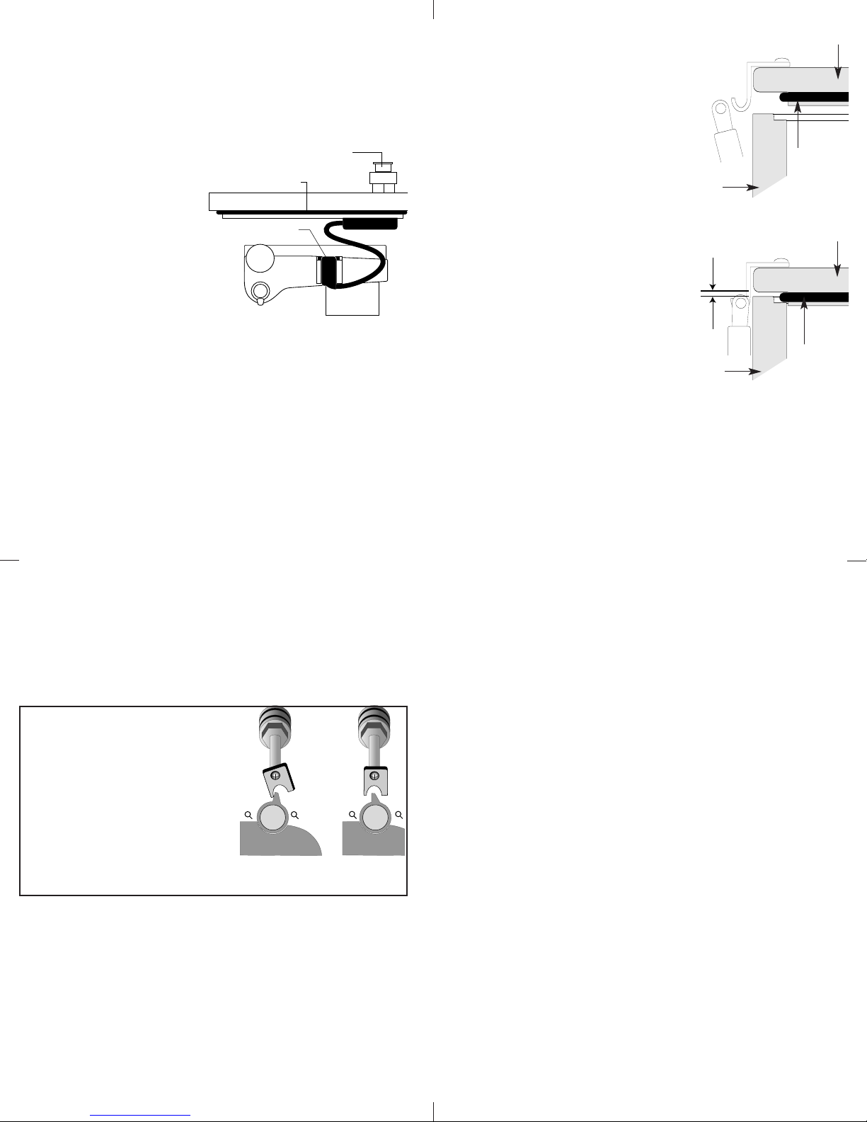
CClloossiinngg tthhee HHoouussiinng
1. Place housing face down in your
g
housing back
lap.
2. Check to see that there is an
o’ring on the housing back and
hat it is clean and in its proper
t
location.
. Guide the back onto the housing.
3
The o’ring should touch the
o’ring
housing all the way around. There
should be an even gap all the way
round between the housing and
a
housing
the housing back.
4. Lift the lid snaps so they are
extended and place the lid snap
housing back
into the hook on the housing
back.
. To close the housing push
5
down on the lid snaps until
even gap
all 4 sides
they snap into place . Lid
snaps on opposite sides of the
housing should be closed at the
same time. Be sure they are down
housing
o’ring
far enough to engage the lock.
DDoouubbllee cchheecck
k
- Once the housing is closed, check the o’ring seal.
Check the gap between the housing back and the housing, it
should be even all the way around.
Look through the clear plastic back at the o’ring. You should see a
darkened area where the o’ring is compressed against the
housing back. If you do not see an even black compression seal
all the way around the back, open the lid snaps, reseat the
housing back and close the lid snaps. Visually check the seal again.
5
CChheecckkiinngg CCoonnttrroolls
s
Once the housing has been closed, push the controls back into
place. Make sure they line up with the camera’s controls.
TTuurrnn CCaammeerraa OOn
n
Turn the camera on and operate each of the housing controls to
get a feel for using the camera in the housing. Take a few
pictures above water with the camera in the housing.
ZZoooomm CCoonnttrrool
l
(NOTE:) After you have used the
housing’s zoom control it must be
returned to the center position to
disengage. If the housing zoom
control is pushing the zoom lever
in either direction the camera
may not take a picture or access
any other function as the camera
is receiving a signal from the
engaged zoom control.
Zoom control
engaged
Zoom control
disengaged
(centered)
6
7
Page 4

UUssiinngg FFllaassh
UUssiinngg tthhee CCaammeerraa’’ss BBuuiilltt--iinn FFllaasshh.
If you do not have an external flash the camera’s built-in flash
can be used. See Diffuser instructions.
NOTE: The camera’s built-in flash cannot be used with optional
Wide-angle lenses.
DDiiffffuusseerr && DDeefflleeccttoorr IInnssttaallllaattiioon
h
.
n
Deflector
Housing shown with
deflector installed.
DDiiffffuusseerr aanndd DDeefflleeccttoorr ccoonntt.
A diffuser and deflector are
included with the housing. The
diffuser is white transparent
plastic. The deflector is also white
ut is not transparent and has a
b
decal on the front.
To install the diffuser or deflector
spread the port clamp at the spring
end and slide over the lens port.
he white plastic should be placed
T
in front of the camera flash. The
port clamp should be pushed back
against the front of the housing.
DDiiffffuusseer
DDeefflleeccttoor
r
The diffuser should be installed when using the camera’s built in
lash. When shooting with the camera’s built-in flash at
f
approximately 2 feet (0.6 m) or less, the lens port on the
housing blocks a portion of the light from the camera’s built-in
flash, creating a shadow in the lower left of the photo. To
eliminate the shadow zoom the lens between 1/3 and 1/2 of its
full telephoto range.
(You can test this above water)
r
The deflector should be installed when using an external strobe
such as the DS51 or DS125 Substrobe and EV Controller. The
deflector will redirect the camera’s flash to the EV Controller
which controls the external strobes output.
.
Port Clamp
Spread to Install
Diffuser/
Deflector
material
Spring
8
LLeennss PPoorrt
t
Treat the glass in the lens port as a camera lens. After use, rinse
and gently dry the lens port to avoid water spotting. To clean
use a mild soap solution or lens cleaner.
Do not use alcohol or window cleaner on the Lens Port.
The Lens Port will accept (2) Wide-Angle Adapters. The WideAngle Adapter #9306.80 which is required to mount the Inon
UWL-150AD Bayonet style wide-angle lens. The Wide-Angle
Adapter 9306.81 is required to mount the following Wide-Angle
Lenses, Inon UWL-100, Sea&Sea #58070 and Ep0que DCL-20
screw thread (67mm) style wide-angle lenses.
These lenses can be secured onto the Wide-Angle Adapter
above or below water as they are designed to have water
between the front of the port and the accessory lens. Make sure
no air bubbles are trapped between the port and the accessory
lens. Any vignetting that occurs can be eliminated by zooming
the camera lens slightly. The camera’s built-in flash cannot be
used with wide angle
lenses. The front of the
lenses are so large they
block the camera’s flash.
To properly light subjects
when using a wide angle
lens an external strobe
should be used. Due to
the wide-angle of
coverage of these lenses,
the DS125 Substrobe is
recommended or two
DS51 Substrobes.
Wide-Angle Adapter
Wide-Angle Lens
9
OOppttiioonnaall AAcccceessssoorriiees
BBaacckk OO’’rriinngg
O’rings last for several years if properly maintained. (See
maintenance) Always carry a spare.
##00111100
UURR//PPrroo FFiilltteerr
The UR/Pro underwater color correcting filter is designed to
restore some of the warm colors filtered out by the water. For
available light use only, not recommended for use with flash.
DDuuaall HHaannddllee TTrraayy
A Dual Handle Tray is available. The Dual Handle Tray provides
a second access point for mounting a second strobe.
SSuubbssttrroobbee PPaacckkaaggeess AAvvaaiillaabblle
#3944.45 DS51, Sync Cord, Strobe Arm Is
#3944.51 DS51, Sync Cord, Strobe Arm SA-100R
#3944.75 DS125, Sync Cord, Strobe Arm SA-100R Smart Charger
UUssiinngg EExxtteerrnnaall FFllaasshh iinn MMaannuuaall MMoodde
To use any power settingbs on an external flash in it’s manual
mode the camera’s flash mode must be set to “Slave Mode”.
In the camera’s menu set-up go to flash mode and select
“Slave Mode”. If Slave Mode is not selected most images will
be underexposed.
s
##66444411..3322
##99552233..1122
e
e
10
1
1
Page 5

OOppttiioonnaall AAcccceessssoorriiees
SSuubbssttrroobbee DDSS5511 PPaacckkaaggee
The Substrobe DS51 package includes
the Substrobe DS51, EV Controller
and ball socket arm. An external
strobe offers several advantages
over using the camera’s built-in
flash. External strobes move the
flash away from the camera lens
hich helps reduce backscatter.
w
They also expand lighting options
o achieve the best lighting for
t
different subjects. A second external
digital strobe package can be added
to fill the shadows and produce
ore realistic photographs.
m
he Substrobe DS51 covers the
T
equivalent of a 28mm lens. It is the
ideal choice when using only the
camera lens or the camera lens
with a macro accessory lens.
If an accessory wide angle lens
wider than 28mm is used, the ideal
lighting choice is the Substrobe
DS125, which covers 100 degrees, or
two Substrobe DS51’s can be used.
s
##33994444..5544
Substrobe
DS51
SA-100Q
Ball Socket
Arm
OOppttiioonnaall AAcccceessssoorriiees
s
SSuubbssttrroobbee DDSS112255 PPaacckkaaggee
The Substrobe DS125 package
includes the Substrobe DS125, EV
Controller, ball socket arm and
charger. An external strobe offers
several advantages over using the
camera’s built-in flash. External
strobes move the flash away from
he camera lens which helps reduce
t
backscatter. They also expand
ighting options to achieve the best
l
lighting for different subjects. A
second external digital strobe
package can be added to fill the
hadows and produce more
s
realistic photographs.
The Substrobe DS125 covers
the equivalent of a 18mm lens,
100 degrees. It is the ideal choice
when using accessory wide angle
lenses greater than 28mm.
##33994444..7777
Substrobe
DS125
SA-100Q
Ball Socket
Arm
12
MMaaiinntteennaanncce
The Ikelite Digital Housing should be given the same care and
attention as your other photographic equipment. In addition to
normal maintenance we recommend that the housing be returned
to Ikelite periodically to be checked and pressure tested.
DDoo NNoot
1.
prolonged periods. Heat may damage the camera.
DDoo NNoot
2.
3. Before using the housing, always check the tightness of the
ssccrreew
w
Check each
they are tight. There is a slight chance that either could vibrate
loose during travel.
4. Keep the back o’ring clean and lightly lubricated. To lubricate
remove the o’ring from the back. Put a small amount of lkelite
lubricant on your fingers. Draw the o’ring through your fingers
to apply a light coating of lubricant. Only apply enough
lubricant to make the o’ring feel slick.
This light coating of lubricant will help to keep the o’ring from
drying out and will help to show a dark sealing line when the
housing back is properly sealed.
5. Keep the area where the o’ring fits and the sealing surface of
the housing clean.
6. Rinse the housing exterior thoroughly in fresh water after each
salt water use. Dry with a soft cloth. Dry lens port to eliminate
water spotting.
After several uses in salt water soak the housing in a mild soap
solution, rinse and dry before storage. When storing the
housing, remove the back o’ring, lightly lubricate and place in a
plastic bag. Place the plastic bag with o’ring inside the housing
for safe keeping.
CCAAUUTTIIOON
e
t
leave the camera and housing in direct sunlight for
t
ship the camera in the housing.
in each control knob.
ccoonnttrrooll ggllaannd
d
penetrating the housing to make sure
DDoo NNoott ssttrreettcchh tthhee oo’’rriinng
N
NNeevveerr uussee sspprraayy lluubbrriiccaannttss aass tthhee pprrooppeellllaanntt iinnggrreeddiieenntt ccaan
ccaauussee tthhee ppllaassttiicc hhoouussiinngg ttoo ccrraacckk.
.
13
sseet
t
g
.
n
14
Page 6

CCoonnttrrooll MMaaiinntteennaanncce
e
Ikelite controls are designed to provide years of reliable service
with minimal maintenance.
1. Push button controls require no maintenance other than rinsing
in fresh water after saltwater use. If a push button control
ecomes difficult to push or if it sticks when depressed, soak the
b
housing in luke warm fresh water. After a few minutes operate
he push button. If this does not correct the problem, return the
t
housing to Ikelite for maintenance.
2. Some of the controls have long shafts. These controls can be
lubricate shaft
housing
3. Some of the controls have a short shaft and cannot be pulled
out exposing the shaft for lubrication. In the unlikely event one
f these controls sticks or becomes difficult to operate you can
o
remove the control from the housing and lubricate it, or return
the housing to Ikelite for maintenance. To remove the control,
loosen the set screw in the knob (allen wrench required);
emove the knob. If there is salt or dirt build-up on the exposed
r
control shaft, clean the shaft. Open the housing and gently slide
he control shaft out of the control gland. Clean and lightly
t
lubricate the shaft, including the end of the shaft. Slide the
haft back into the control gland and gently slide it back and
s
forth a few times without fully removing the shaft from the
gland. Replace the knob, NOTE the flat area on the shaft, the
set screw in the knob should tighten down against the flat area
n the control so the knob does not turn on the shaft.
o
pull out to
expose shaft
pulled out, exposing the shaft (see drawing).
To lubricate the control, gently pull on the knob until the
stainless steel shaft is exposed. Lightly lubricate the shaft, then
move the shaft in and out several times. This will lubricate the
x’ring in the Ikelite control gland. This should be done before
using the housing after a prolonged storage period, or once a
week when the housing is in use.
15
GGeenneerraall TTiipps
s
1. Due to the power required to operate the camera, flash, and
LCD screen it is a good idea to start each dive with a fresh set of
batteries.
2. Some cameras reset their flash to AUTO when the camera is
turned on. If you prefer another setting be sure to select it.
3. As soon as you enter the water, take a moment and check the
housing to see that it is properly sealed.
Next, check to see if there are any bubbles on the face of the
4.
lens port. If there are, take your finger and remove them. If
there are bubbles on the lens port they can produce soft focus
spots in your photographs.
5. If you use the housing Zoom control, make sure to move it back
to the center position. If the housing Zoom control is pushing
the camera zoom lever to either side the camera will not
function. (See page 6)
NNOOTTE
E
6. If you are shooting with the camera’s built-in flash at
approximately 2 feet (0.6 m) or less, zoom the lens to
maximum telephoto. The lens port on the housing blocks a
portion of the light from the camera’s built-in flash when
shooting close up. If you do not zoom to maximum telephoto, a
shadow may appear in the lower left corner of close-up
photographs.
(You can test this above water)
To shoot wide angle photographs closer than 2 feet (0.6m), you
need to use a preflash compatible external strobe such as the
DS51 or DS125. With an external strobe you can position it so
nothing blocks the light path between the strobe and the
subject.
control
shaft
Flat
Tighten set screw down
against this area when
replacing the knob.
housing
Lubricate end of shaft
before reinserting into
gland
gland
Loosen set screw
(allen wrench required)
16
PPhhoottoo TTiipps
s
1. The number one rule in underwater photography is eliminate as
much water between camera and subject as possible. Get as
close as you can to the subject, then use the zoom. If you are
using flash, subjects beyond 6 feet (1.8m)will not have much
color.
2. The camera’s built-in flash is very close to the camera lens. The
flash can light up any suspended particles in the water and they
can be recorded in your picture. This effect is called backscatter.
To eliminate as much backscatter as possible, photograph close.
Photograph in clear water; do not stir up the sand or silty
bottom. If backscatter becomes a problem in the environment
you are photographing, an external flash will help eliminate
much of the backscatter.
3. Digital cameras have a slight lag time between when you press
the shutter release button and the camera actually takes the
picture. Hold the camera steady a second or two after pressing
the shutter release button.
4. Do not shoot down on subjects as they will quite often blend
into the background and be difficult to see in the photograph.
Shoot subjects straight on or shoot up at a slight angle using
the blue water as a contrasting background.
5. Underwater flash is used to restore the warmer colors filtered
out by the water as well as to illuminate the subject. When
photographing underwater, set the camera to use flash on
every shot. If the camera’s flash is set to AUTO and the sun is
behind your subject, the camera may see enough light that it
does not fire the flash. With the sun behind the subject the
subject is shaded (dark) and needs flash for a good exposure.
17
18
Page 7

PPhhoottoo TTiippss CCoonntt.
6. Using daylight or flash each person has their idea of what is the
correct exposure. Since these opinions vary you may want to
adjust your camera for what you like exposure wise. Many
cameras allow you to adjust both available light and flash
xposure with an EV control.
e
. Many photographers transfer their images to the computer
7
where they can fine tune the appearance of the image. Many of
the image manipulation programs make you think you can
magically correct any image taken and make a good picture.
ne thing to remember when using image manipulation
O
programs, if the image is overexposed much of the color is
missing. If the color is missing you cannot adjust it. If images
are underexposed the color is there, it is just dark and you can
adjust it to some degree. So if you error in exposure it is better
to have the image slightly underexposed than over exposed.
.
IIkkeelliittee LLiimmiitteedd WWaarrrraanntty
All Ikelite products are warranted against any manufacturing
defects for a period of one (1) year from the date of purchase.
Defective products should be returned prepaid to Ikelite. Ikelite
will, at its discretion, repair or replace such products, and will
eturn to customer prepaid. All other claims, of any nature,
r
including but not limited to bulb failure are not covered. Except as
entioned above, no other warranty expressed or implied, applies
m
to this Ikelite product.
RReettuurrnniinngg PPrroodduuccttss ffoorr SSeerrvviicce
kelite is most interested in preforming any service to assure that
I
all products perform as intended. For repair or service, return
the product to the address below with your name, address,
phone number and a brief description of the problem. Evidence
f purchase date must be provided to obtain warranty service.
o
y
e
19
IIkkeelliittee UUnnddeerrwwaatteerr SSyysstteemms
5500 WW 3333rrdd SSttrreeeet
IInnddiiaannaappoolliiss,, IINN 4466220088 UUSSA
331177--992233--4455223
eemmaaiill:: iikkeelliittee@@iikkeelliittee..ccoom
wwwwww..iikkeelliittee..ccoom
t
3
m
m
DDiiggiittaall 66113322..3355--0022--0011006
s
A
6
 Loading...