

Ikelite 6038.32 Supplemental Instructions

IIKKEELLIITTEE VVIIDDEEOO CCAASSEE
SSUUPPPPLLEEMMEENNTTAALL IINNSSTTRRUUCCTTIIOONNSS FFOOR
R
##66003388..3322 SSoonnyy DDCCRR--DDVVDD--9911,, DDVVDD--110011,, DDVVDD--220011,, DDVVDD--33001
1
This supplemental set of instructions describes additional features specific to your
housing model. Prior to testing the system in the water, please read this supplement
along with the general instruction manual to become familiar with its features and
functions.
Ikelite Video Cases are slightly negative in salt water for stability. This housing has
been water pressure tested at the factory and has a working depth of 60m (200').
HHOOUUSSIINNGG CCOONNTTRROOLLS
S
_______________________________________________________________________________________________________________
_
• Power On/Off / Mode
• Start/Stop
• Power Zoom
• Photo
MMAAIINN OO--RRIINNGG ##00110099_____________________________________________________________________________________________________
_
O-rings last several years if properly maintained. Control seals should not need
to be replaced as long as the control shafts are kept clean and lightly lubricated.
Port
Base
Bottom Bar
Photo
Eyeport
Power/
Mode
Start/
Stop
Po w
er Z
oo
m
PPRREEPPAARRAATTIIOON
N
PPAACCKKAAGGEEDD WWIITTHH HHOOUUSSIINNGG_________________________________________________________________________________________
_
• External UR/Pro Color Filter
• Silicone Lubricant
• Lens Shade
CCOOLLOORR FFIILLTTEERR_________________________________________________________________________________________________________________
_
The installation and usage of the external UR/Pro color filter is described in the
general instruction manual.
LLEENNSS SSHHAADDEE_____________________________________________________________________________________________________________________
_
The internal lens shade, provided with the housing, helps block light reflection/
refraction caused by the interaction of the external color filter and the lens port.
Carefully thread the lens shade on the front of the camera lens. The lens threads are
very fine;
DDOO NNOOTT
cross thread. It should screw on very easily. If it is difficult to turn,
you are cross threading.
Completely thread the lens shade into the camera to avoid any potential clearance
or sealing problems when the camera is installed and the housing is sealed.
OOPPTTIIOONNAALL WWIIDDEE AANNGGLLEE LLEENNSS_____________________________________________________________________________________
_
The lens port on the front of the housing accepts the optional wide-angle lenses
offered by Epoque (DCL-20), Inon (UWL-100) and Sea&Sea (58070). These waterproof
lenses secure to the outside of the lens port, and are not marketed by Ikelite.
Should you elect to use the optional Epoque, Inon or Sea&Sea lens, carefully thread
the waterproof lens on the front of the lens port. The lens threads are very fine;
DDOO NNOOT
T
cross thread. It should screw on very easily. If it is difficult to turn, you are
cross threading.
There is another optional wide-angle lens available, which secures directly to the
front of the camera lens, inside the housing. Sony offers the optional X0.6 conversion
wide-angle lens VCL-0625S, available from Sony, which is compatible with this camera
system.
External
Color Filter
Internal
Lens Shade
SSUUPPEERR--EEYYEE VVIIEEWWFFIINNDDEERR_____________________________________________________________________________________________
_
See exactly what the camera sees underwater using the camera's electronic
viewfinder in conjunction with the Ikelite Super-Eye, which is permanently mounted
in the eyeport on the clear back plate. The Super-Eye extends the viewfinder image to
provide enhanced viewing underwater.
LLCCDD MMOONNIITTOORR_________________________________________________________________________________________________________________
_
The camera's LCD monitor can be viewed thru the side of the housing. Open the
LCD monitor on the camera, rotate 180°, and then press it back against the side of the
camera so that the LCD monitor is visible.
To view the image on the LCD monitor from the rear of the housing, Ikelite offers
optional External Mirror #9290.95, which adheres to the outside of the housing. Then
the LCD image can be viewed from the rear.
BBAATTTTEERRYY AANNDD TTAAPPEE_______________________________________________________________________________________________________
_
Install a fully charged Sony battery on the camera:
Sony NP-FP50, NP-FP70, NP-QM71
The Sony NP-FP70 and NP-QM71 batteries overhang the back of the camera tray
slightly.
Other brand batteries may not fit inside the housing. If the battery selected
overhangs the camera tray by a dimension greater than 8mm (5/16"), then the batter
is too large and will cause the housing to leak.
Make sure you have loaded an appropriate Sony disk in the camera.
FFIINNAALL PPRREEPPAARRAATTIIOONN_____________________________________________________________________________________________________
_
Remove the lens cap and cord from the camera. Otherwise, they may interfere with
the housing seal.
The camera's auto focus feature is utilized underwater. For best results, move in
close to your subject and use the wide-angle range to shoot thru as little water as
possible. Full range zoom range is accessible underwater. Chart shows recommended
initial settings underwater.
CCAAMMEERRA
A
SSEETTTTIINNG
G
Power On/Off – Camera (On)
Zoom Lever – Wide Angle Setting
Focus – Auto Mode
Exposure – Auto Mode
IINNSSTTAALLLLAATTIIOON
N
CCAAMMEERRAA TTRRAAYY_________________________________________________________________________________________________________________
_
Note the placement of the camera tray underneath the guides, and note the two
white-color locks on the inside wall of the housing that secure the tray in place. Gently
push up on the white tray locks to release the camera tray, and slide the tray out of the
housing.
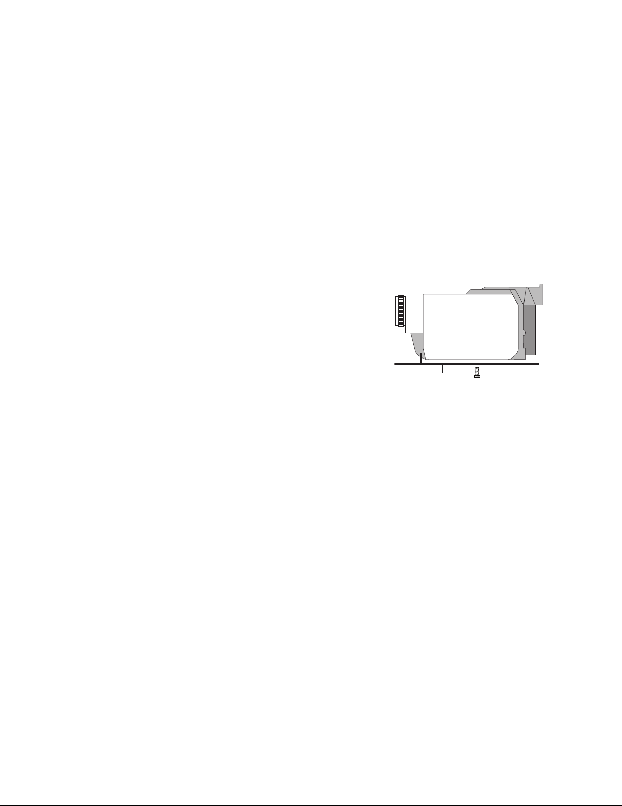
Place the camera between the stabilizing pins on the tray. Secure camera with the
tripod mounting bolt. The camera should fit easily on the tray and should be parallel
with the sides of the tray.
IINNSSEERRTTIINNGG TTHHEE CCAAMMEERRAA_____________________________________________________________________________________________
_
Pull the housing controls out to provide clearance for the camera. Slowly slide the
camera tray (with camera mounted) back into the housing.
DDOO NNOOT
T
force this installation; if the controls are out of the way and everything is
lined up properly, the camera and tray will fit easily inside. Make certain that the tray is
completely in the housing, and make sure that both white tray locks have locked the
camera tray in place.
HHOOUUSSIINNGG CCOONNTTRROOLLSS_____________________________________________________________________________________________________
_
Slide the housing controls back in place making sure they properly align with the
camera functions.
Operate each control to see how it works with the camera. Some controls such as
start/stop will be used frequently. Other controls may seldom be utilized. Refer to your
camera owner's manual for the proper function of each camera control. Look thru the
back to be sure that you can see into the viewfinder.
When using the housing controls, especially the start/stop,
DDOO NNOOTT
use excessive
force because you could damage the camera.
CCAAUUTTIIOON
N
Remove the lens cap and cord from the camera. Otherwise, the cord may interfere with the housing
seal. If the housing controls are not properly positioned, they could interfere with the housing seal.
IIKKEELLIITTEE UUNNDDEERRWWAATTEERR SSYYSSTTEEMMS
S
50 West 33rd Street • PO Box 88100 • Indianapolis, IN 46208 USA • 317.923.4523
Email: ikelite@ikelite.com
• www.ikelite.com
6038.32-06-0806
Camera Mounting Bolt
Camera Tray
 Loading...