

Page 1
TTL Converter for Nikon DSLR with
Ikelite Connector (Version 2)
Product Number 4301.3
I n s t r u c t i o n M a n u a l
Thank you for your purchase of Ikelite equipment. Please read this
instruction manual completely before attempting to operate or dive
with this product.
Page 2

Table of Contents
Included in the Box ..............................................................3
Camera Compatibility............................................................3
General Information ..............................................................4
Strobe Compatability ............................................................5
Connecting the Adapter........................................................5 - 6
Switching between TTL and Manual....................................6
Customer Support ................................................................7
Returning Products for Service ..........................................7
Spare Parts ............................................................................Back Page
Limited Warranty ..................................................................Back Page
2
Page 3
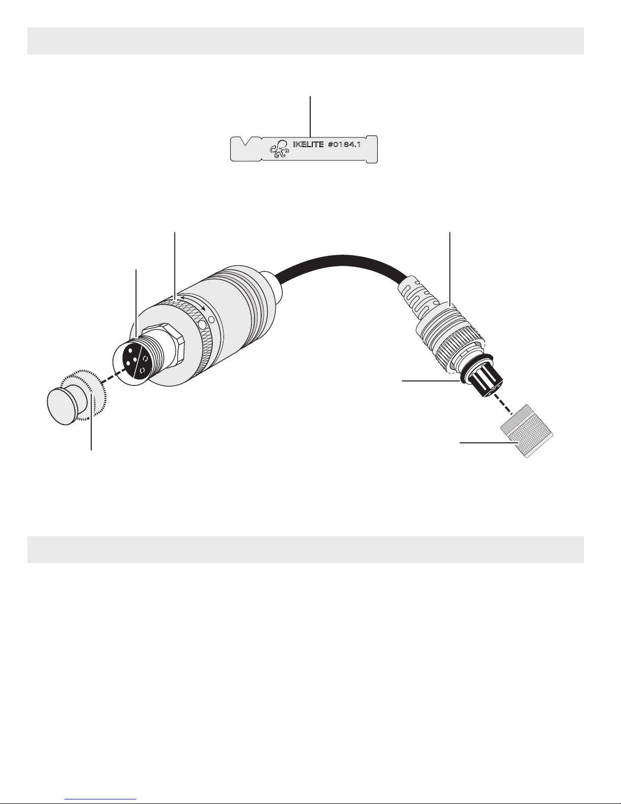
Included in the Box
Silicone Lubricant
IKELITE #0184.1
Silicone Lube
Knurled Ring
Ikelite Bulkhead
Waterproof Bulkhead Cap
Ikelite Connector
T
T
L
O-ring
Ikelite Connector
Protector
Camera Compatibility
- Nikon D2X, D3, D4
- Nikon D40, D50, D60, D70, D70s, D80, D90
- Nikon D200, D300, D300s
- Nikon D600, D610, D700, D750
- Nikon D800, D810
- Nikon D5000, D5100, D5200, D5300
- Nikon D7000, D7100, D7200
- Fuji S5 Pro
3
Page 4

General Information
The TTL Converter is equipped with a simple rotating switch that allows
toggling between TTL and manual exposure.
Exposure compensation is NOT provided through the Adapter, but may
be accessed through a camera button or the camera's built-in menu.
Proper operation and TTL exposure requires use of a current-model
Ikelite DS strobe - see Strobe Compatibility, Page 5.
Use of this TTL Converter requires an Ikelite 5-pin electrical bulkhead
strobe connector and TTL hotshoe. If you are unsure whether your
housing meets these requirements, please contact the housing
manufacturer. Wiring diagrams for our Ikelite connectors can be found at
ikelite.com.
One or two strobes may be connected to the Converter using an
Ikelite-to-Ikelite single or dual sync cord. Use of two strobes requires a
dual sync cord. Two strobes cannot be controlled by individual separate
Converters even if the housing is equipped with two bulkhead
connectors.
TTL Converters are not usable with non-Ikelite strobes or non-DS series
Ikelite strobes.
Due to hardware changes and risk of cord damage, we are unable to
modify existing 4301, 4301.2, 4302, or 4302.2 Converters to the newest
TTL protocol.
Please also note that strobe serial number requirements differ from the
original Nikon TTL Converter - see Strobe Compatibility, Page 5.
The Ikelite TTL Adapter is NOT compatible with the following Nikon
Cameras; D-100, D-1X, D-2H.
4
Page 5

Strobe Compatibility
AF35 ......................no
DS50 ......................above serial number 75510 with update
DS51 ......................above serial number 78700
DS160, DS161........all
Non-Ikelite ..............no
Connecting the Adapter
Use Adapter with Ikelite DS Strobes ONLY. If using an older DS50 or
DS125 strobe, see Strobe Compatibility above.
1. Make sure all components are dry.
2. Remove Waterproof Bulkhead Cap and Connector Protector, Page 3.
3. Clean and lightly lubricate the threads and o-ring on the male Ikelite
connector. Use ONLY Ikelite lube. Other brand lubricants can cause the
o-ring to swell and not seat properly. Check o-ring for cracks or nicks.
4 Note the positioning of the receptacles and pins. Properly align the
Ikelite Connector and insert it into the housing’s Ikelite-style bulkhead;
hand-tighten Knurled Ring.
5. Connect your Ikelite Sync Cord to the Adapter Bulkhead. Hand tighten the
Knurled Ring on the Sync Cord until there is no in-out movement
- reference Diagram A, Page 6
between the Ikelite Sync Cord Connector and Adapter bulkhead.
Hold the adapter’s knurled ring when tightening the sync cord.
CAUTION: Do not use tools on, or over-tighten Knurled Rings.
Single or Dual Ikelite sync cords can be attached.
Dual strobe use requires dual sync cord.
Two strobes cannot be operated by independent adapters.
5
Page 6

Connecting the Adapter - continued
Diagram A
Adapter
Bulkhead
Ikelite Connector
Knurled Ring
T
T
L
Adapter Knurled Ring
White Dot
Ikeli te Sync Cord Connector
Knurled Ring
To Housing
Bulkhead
Switching between TTL and Manual
The Knurled Ring on the TTL Adapter’s black delrin pod has a White Dot,
Diagram A.
The Knurled Ring can be rotated clockwise or counterclockwise to align
the White Dots for TTL or Manual operation.
The DS Strobe must be set to TTL mode for the Adapter to provide
TTL operation.
6
Page 7

Customer Support
Ikelite Underwater Systems
Service Department
50 West 33rd St.
Indianapolis, IN 46208 USA
Email: ikelite@ikelite.com
Phone: 317-923-4523
Returning Products for Service
Ikelite is most interested in performing any service to ensure that all
products perform as intended. Evidence of purchase date must be
provided to obtain warranty service.
No prior authorization is required. You may return directly to us or
through your dealer. Please include a brief description of the problem,
any relevant email correspondence, and/or instructions on what you
want us to do. Always include name, shipping address, email address,
and phone number inside of the package. Send postage paid to:
Ikelite Underwater Systems
Attention: Service Department
50 West 33 Street
Indianapolis, IN 46208 USA
No reimbursements for postage paid will be issued.
You may also want to insure the package.
Returning Products for Service -
outside the United States
For the separate international customs documentation form that you
complete to accompany the shipment, please state or designate that the
enclosed products were originally manufactured in the USA and are
being returned to the manufacturer for repair service. Value of the
equipment listed for customs purposes should be zero.
7
Page 8

Spare Parts
0301.12 ..........Connector Protector for Ikelite plug
9104.5 ............Waterproof Bulkhead Cap
0118 ................O-ring
0184.2 ............silicone lubricant 2cc recloseable tube
Limited Warranty
This Ikelite product is warranted against any manufacturing defects for a
period of one (1) year from the original date of purchase. Defective
products should be returned to Ikelite postage paid. Ikelite will, at its sole
discretion, r
postage paid. All other claims of any nature are not covered. Except as
mentioned above, no other warranty expressed or implied applies to this
Ikelite product.
epair or replace such products, and will return to customer
Ikelite Underwater Systems
50 West 33rd Street
Indianapolis, IN 46208 USA
© 2015 Ikelite Underwater Systems
4301.3_TTL_Converter_Nikon_Ike_to_Ike_Version_2_01-1015
ikelite.com
 Loading...