

Ikegami OCP-300 Operation Manual
㻌
㻌
㻌 㻌 㻌 㻌 㻌 㻌
Products conforming to RoHS directive
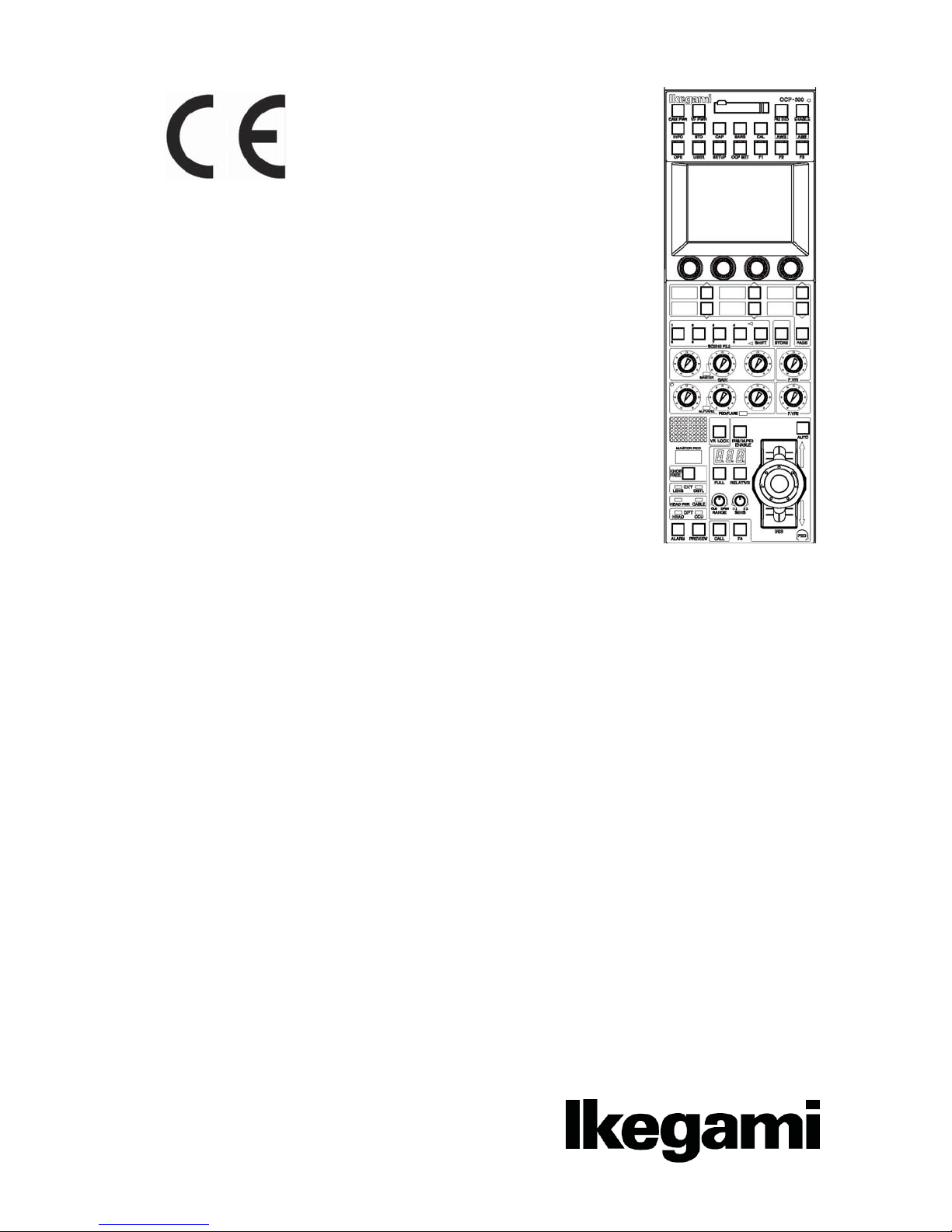
OCP-300
Operation Control Panel
㻻㼜㼑㼞㼍㼠㼕㼛㼚㻌㻹㼍㼚㼡㼍㼘㻌

㻌 㻌 㻌
㻌
㻌 㻌 㻌
㻌
㻌
㻌
㻌
Products conforming to RoHS directive
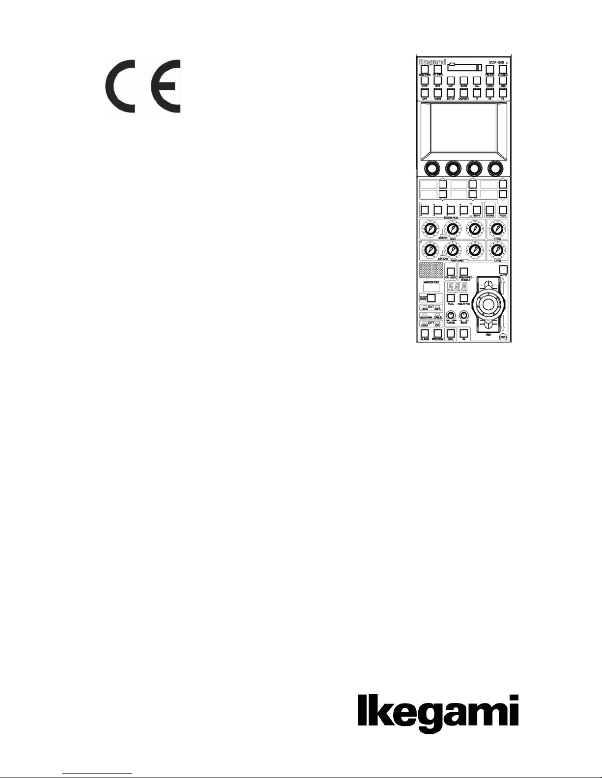
OCP-300
Operation Control Panel
㻻㼜㼑㼞㼍㼠㼕㼛㼚㻌㻹㼍㼚㼡㼍㼘㻌
1406 1st Edition (U) (E)
㻌
㻌
㻌
㻌
Copyright © 2010 Ikegami Tsushinki Co., Ltd
We reserve the copyright on the software we create.
No part of this publication may be modified or reproduced in any form, or by any means, without prior written permission from
Ikegami Tsushinki Co., Ltd.

PRODUCTS CONFORMING TO RoHS DIRECTIVE i
㻌
㻌
PRODUCTS CONFORMING TO RoHS DIRECTIVE
Following products described in this manual are products conforming to RoHS directive.
•OCP-300 Operation Control Panel
Products conforming to RoHS directive include products that do not contain specified hazardous substances such
as lead, mercury, cadmium, hexavalent chromium, polybrominated biphenyl (PBB) and polybrominated
diphenyl ether (PBDE) in electrical and electronic equipment excluding following exemption applications based
on the EU directive (Directive2002/95/EC).
* About RoHS Directive
The RoHS directive stands for “the Restriction of the Use of Certain Hazardous Substances in Electrical and
Electronic Equipment” and is one of environmental directives in Europe. This directive restricts the use of
specified hazardous substances in electrical and electronic equipment.
ɜ!Applications exempted from RoHS directive compliance
Followings applications are permitted as exemptions from RoHS directive compliance.
1. Mercury in compact fluorescent lamps not exceeding 5mg per lamp
2. Mercury in straight fluorescent lamps for general purposes not exceeding:
· halophosphate 10mg
· triphosphate with a normal lifetime 5mg
· triphosphate with a long lifetime 8mg
3. Mercury in straight fluorescent lamps for special purposes
4. Mercury in other lamps not specifically mentioned in this Annex
5. Lead in the glass of cathode ray tubes, electronic components and fluorescent tubes
6. Lead as an alloying element in steel containing up to 0.35% lead by weight, aluminum containing up to 0.4%
lead by weight and as a copper alloy containing up to 4% lead by weight
7. Lead in following items
· Lead in high melting temperature type solders (i.e. tin-lead solder alloys containing more than 85% lead)
· Lead in solders for servers, storage and storage array systems
· Lead in solders for network infrastructure equipment for switching, signaling, transmission as well as
network management for telecommunication
· Lead in electronic ceramic parts (e.g. piezoelectronic devices)
8. Cadmium plating except for applications banned under Directive 91/338/EEC amending Directive
76/769/EEC relating to restrictions on the marketing and use of certain dangerous substances and
preparations
9. Hexavalent chromium as an anti-corrosion of the carbon steel cooling system in absorption refrigerators
10. Lead used in compliant pin connector systems
11. Lead as a coating material for the thermal conduction module C-ring
12. Lead and cadmium in optical and fi lter glass
13. Lead in solders consisting of more than two elements for the connection between the pins and the package of
microprocessors with a lead content of more than 80% and less than 85% by weight
14. Lead in solders to complete a viable electrical connection between semiconductor die and carrier within
integrated circuit Flip Chip packages
15. Decabrominated diphenyl ether (Deca-BDE) in polymeric applications
ii MAINTENANCE OF PRODUCTS CONFORMING TO RoHS DIRECTIVE
㻌
㻌
MAINTENANCE OF PRODUCTS CONFORMING TO RoHS DIRECTIVE
Work with care about followings for maintenance of products conforming to RoHS directive.
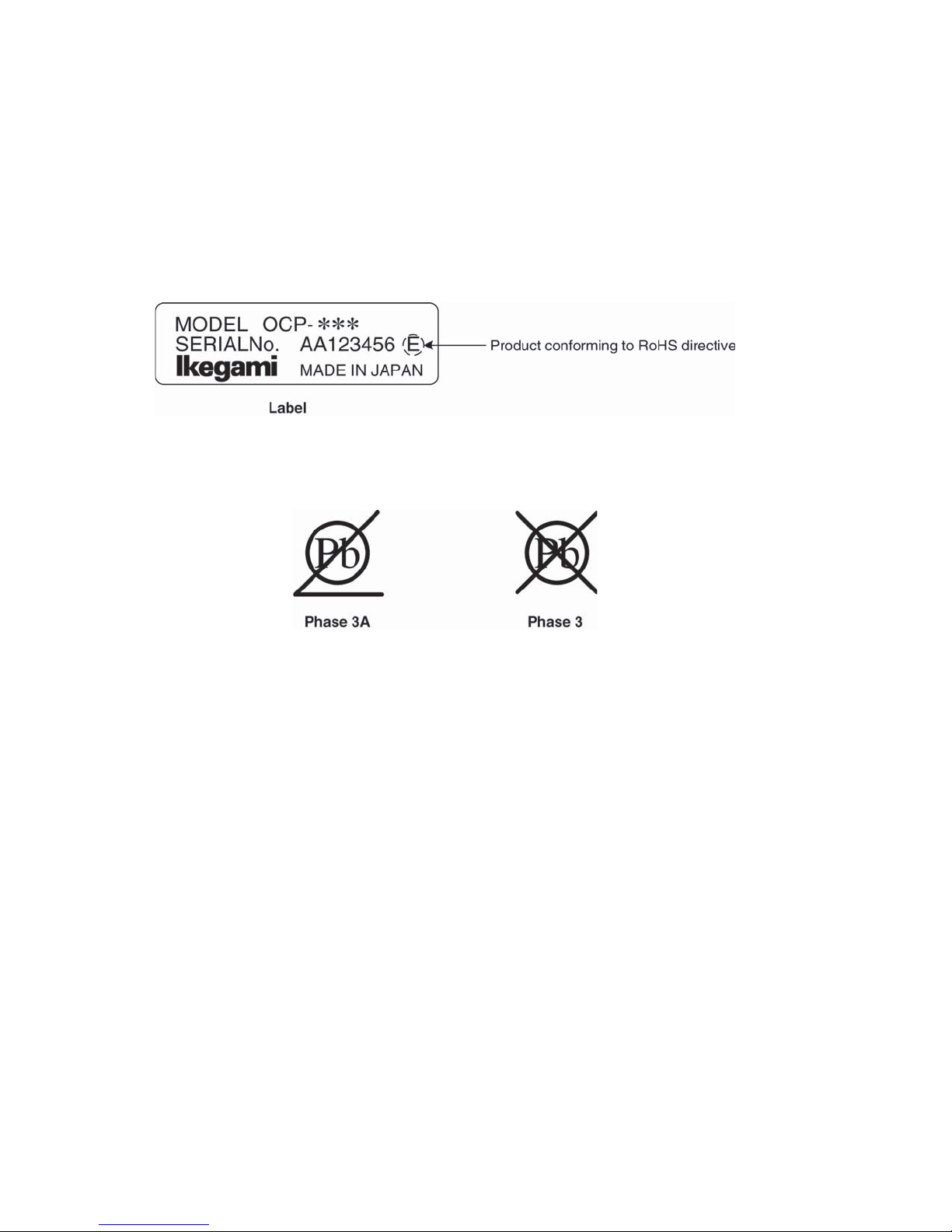
1. Identification
· For products conforming to RoHS directive, the letter “E” is appended at the end of the serial number on the
label. For models that the letter cannot be appended to the serial number, the letter “E” will be described in a
distinguishable position on the label. A description example on a main label is shown below.
· Print-circuit board of the products conforming to RoHS directive is manufactured by following methods.
[1] Blue resist ink is used for the print-circuit board. (The color of conventional print-circuit board is green.)
[2] Either one of the following marks is indicated by a serigraph or label.
2. Soldering
Since the melting point of lead-free solder used for the products conforming to RoHS directive is 20 to 45
degrees Celsius higher than that of conventional solder with lead (Sn-Pb eutectic solder), a high temperature
needs to be set to a soldering iron. Taking allowable temperature limit of the parts and stable work into
consideration, use a soldering iron with excellent thermal recovery characteristics.
· Recommended solder composition is “Sn/3.0Ag/0.5Cu” or equivalent.
· Separate the soldering iron exclusively for RoHS products and the soldering iron for conventional use.
· Set the temperature of the soldering bit to 350 to 370 degrees Celsius.
The temperature may need to be adjusted according to the size of the copper foil land on the print-circuit
board and the tip width of the soldering bit.
· Finish by a lead-free solder looks dull or whitish compared to conventional solder with lead.
3. Parts
Be sure to use parts conforming to RoHS directive.

INFORMATION TO THE USER iii
INFORMATION TO THE USER
This equipment has been tested and found to comply with the limits for a Class A digital device, against harmful
interference when the equipment is operated in a commercial environment. This equipment generates, uses, and
can radiate radio frequency energy and, if not installed and used in accordance with the instruction manual, may
cause harmful interference to radio communications.
Operation of this equipment in a residential area is likely to cause harmful interference in which case the user
will be required to correct the interference at his own expense.
Changes or modifications not expressly approved by the party responsible for compliance could void the user’s
authority to operate the equipment.
The
EN55103-1, EN55103-2 (for the Electromagnetic environment E4-E5).
Use shielded cable except AC cable.
This equipment doesn’t intend to use at residential areas, so that use in residential areas may cause
interference.
The Ethernet cable, please use a shielded cable always.
Please attach a core to a cable to connect to a connector of command, EXT-1 and EXT-2 by all means.
Please make an inquiry to us about the installation of the core, if necessary.
mark means that the following products will meet the Directives 2004/108/EC and standards
iv SAFETY PRECAUTIONS
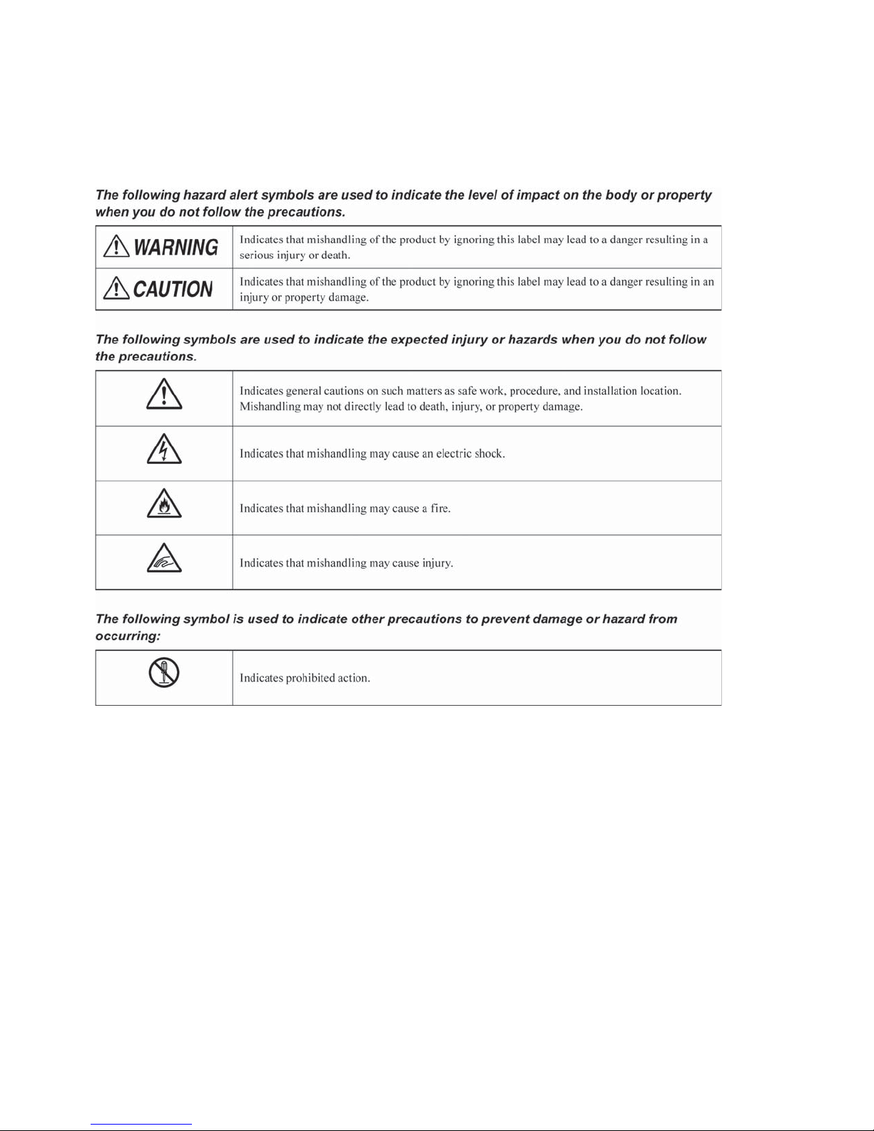
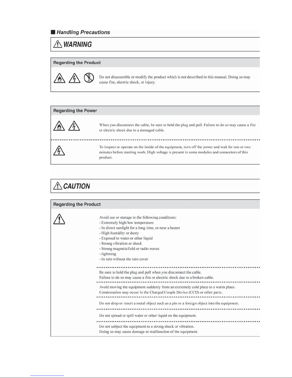
SAFETY PRECAUTIONS
This manual describes the precautions using various pictorial symbols for you to use the product safely. Please
read these precautions thoroughly before use. The symbols and meanings are as follows:
SAFETY PRECAUTIONS v
vi SAFETY PRECAUTIONS
HOW TO READ THE OPERATION MANUAL vii
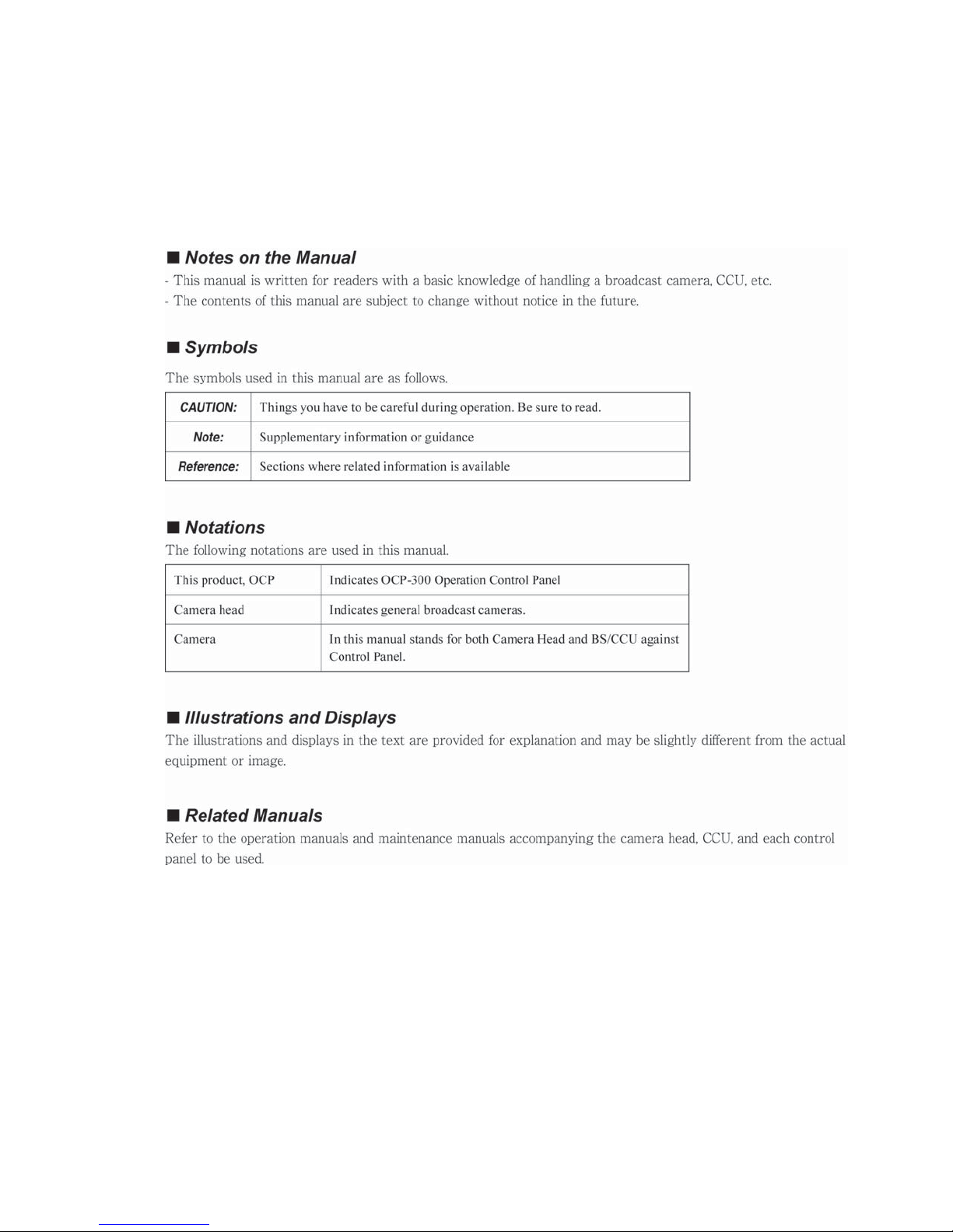
HOW TO READ THE OPERATION MANUAL
This page explains general notes on reading the BSH-300 Operation Manual, and the symbols and notations
used in the manual.


OCP-300
䠍䠊
䠍䠊䠍㻌
䠍䠊䠎㻌
䠍䠊䠏㻌
䠎䠊
䠎䠊䠍㻌
䠎䠊䠎㻌
䠎䠊䠏㻌
䠎䠊䠐㻌
䠎䠊䠑㻌
䠎䠊䠒㻌
䠎䠊䠓㻌
䠎䠊䠔㻌
䠏䠊
䠏䠊䠍㻌
㻌
㻌
㻌
䠏䠊䠎㻌
㻌
㻌
㻌
㻌
䠐䠊
䠐䠊䠍㻌
䠐䠊䠎㻌
䠐䠊䠏㻌
䠐䠊䠐㻌
䠐䠊䠑㻌
䠑䠊
䠑䠊䠍㻌
䠑䠊䠎㻌
䠑䠊䠏㻌
䠑䠊䠐㻌
Operation Control Panel
Operation Manual
Contents
Contents㸯
Overview㻌……………………………………………………………………………………… 1- 1
Overview㻌……………………………………………………………………………… 1- 1
Features㻌……………………………………………………………………………… 1- 1
External view㻌………………………………………………………………………… 1- 3
The Name and Function of Each Part㻌…………………………………………………… 2- 1
Camera Function Control Unit㻌…………………………………………………… 2- 2
LCD Menu-Operations Part㻌………………………………………………………… 2- 5
Selection Function Control Unit㻌………………………………………………… 2- 7
Control Knob Part㻌…………………………………………………………………… 2- 9
Iris/Pedestal Control Section (VR TYPE)㻌……………………………………… 2-11
Iris/Pedestal Control Section (JOYSTICK TYPE)………………………………… 2-14
Status Display Part㻌………………………………………………………………… 2-17
Connector Panel㻌…………………………………………………………………… 2-20
About a Network㻌…………………………………………………………………………… 3- 1
ARC Network㻌………………………………………………………………
3.1.1㻌 Network Key Map㻌……………………………………………………………… 3- 1
3.1.2
LCD Menu㻌……………………………………………………………
Operation of the Control Knob㻌……………………………………………
System Configuration Example㻌………………………………………………
3.1.3
Setup of ARC Net ID㻌……………………………………………………………
Network Connection㻌……………………………………………………………
3.1.4
Ethernet㻌……………………………………………………………………………… 3- 8
3.2.1
Network Key Map
Ethernet Connection Method
3.2.2
Basic Constitution and Basic Operation㻌………………………………………… 4- 1
INFO㻌………………………………………………………………………
OPE㻌…………………………………………………………………………
SET UP㻌………………………………………………………………………………… 4- 7
OCP Setup㻌………………………………………………………………
Camera Data Adjustment㻌……………………………………………
Control Method with OCP-300㻌…………………………………………………… 5- 5
Reconnection Process㻌……………………………………………
Knob Free Function㻌………………………………………………………………… 5- 8
…………………………………………………………… 3- 8
……………………………………………… 3- 9
……………………… 4- 1
………… 3- 1
…………… 4- 3
………… 4- 3
…………… 4-37
……………… 5- 1
……………… 5- 1
………………… 5- 6
3- 2
3- 4
3- 4

䠒䠊
䠒䠊䠍㻌
䠒䠊䠎㻌
䠒䠊䠏㻌
䠓䠊
䠓䠊䠍㻌
䠓䠊䠎㻌
䠓䠊䠏㻌
䠔䠊
䠔䠊䠍㻌
䠔䠊䠎㻌
䠔䠊䠏㻌
䠔䠊䠐㻌
䠕䠊
䠕䠊䠍㻌
䠕䠊䠎㻌
䠕䠊䠏㻌
䠕䠊䠐㻌
䠕䠊䠑㻌
䠕䠊䠒㻌
䠕䠊䠓㻌
䠕䠊䠔㻌
䠍䠌䠊
䠍䠌䠊䠍㻌
䠍䠌䠊䠎㻌
䠍䠍䠊
䠍䠍䠊䠍㻌
䠍䠍䠊䠎㻌
䠍䠍䠊䠏㻌
䠍䠍䠊䠐㻌
䠍䠍䠊䠑㻌
䠍䠍䠊䠒㻌
䠍䠍䠊䠓㻌
䠍䠎䠊
䠍䠎䠊䠍㻌
䠍䠎䠊䠎㻌
䠍䠎䠊䠏㻌
䠍䠎䠊䠐㻌
䠍䠎䠊䠑㻌
㸰 Contents
Absolute Iris Control㻌…………………………………………………
…………………… 6- 1
Clearing the Iris Manual File㻌……………………………………………………… 6- 2
Auto Iris Operation㻌………………………………………………………………… 6- 2
Initial Mode㻌…………………………………………………………………………… 6- 2
Relative Iris Control㻌……………………………………………………………………… 7- 1
Clearing the Data of Other Control Panel㻌……………………
Auto Iris Operation㻌………………………………………………
Initial Mode㻌……………………………………………………
………………… 7- 1
………………… 7- 3
……………………… 7- 4
Manual Setting/Manual Clearing㻌………………………………………………………… 8- 1
Manual Setting/Manual Clearing on the LCD Screen㻌………………………… 8- 1
Indication of the Control Data Offset㻌…………………………………………… 8- 3
Manual Bulk Clearing by the Control Knob Operation㻌……………………… 8- 5
All Manual Setting/All Manual Clearing㻌………………………………………… 8- 7
How to Use the Memory Card㻌…………………………………………………
………… 9- 1
Types and Capacities of Memory Cards㻌………………………………………… 9- 1
Inserting and Removing the Memory Card㻌…………………………………… 9- 2
Creating the Memory Card Name and File Name㻌……………………………… 9- 3
Saving the File Data to the Memory Card㻌……………………………………… 9- 4
Invoking the File Data from the Memory Card㻌………………………………… 9- 7
Deleting the File Data from the Memory Card㻌………………………………… 9-10
Updating the Firmware by Using a Memory Card㻌……………………………… 9-11
Indicating the Message of Each Type㻌…………………………………………… 9-12
Information㻌………………………………………………………………
………………… 10-1
Screen Description㻌………………………………………………………………… 10-1
Direct Jump Function㻌………………………………………………
……………… 10-9
Setting the Panel Assignment and Program Number㻌……………………………… 11-1
Setting the ARCnet ID㻌…………………………………………………………… 11-1
Setting the IP Address/Subnet Mask/Default Gateway㻌……………………… 11-4
Program Number㻌…………………………………………………………………… 11-7
Program Number for Changing the Panel Assignment㻌……………………… 11-8
Display Mode of Program Number㻌……………………………………………… 11-9
Setting the program number function for BS/CCU㻌…………………………… 11-12
Availability of Display Mode and Program Number Function㻌……………… 11-14
Operation Range Setting Function㻌…………………………
………………………… 12-1
Function Overview㻌………………………………………………………………… 12-1
Setting Procedure of Operation Range㻌………………………………………… 12-1
How to Change the Password㻌…………………………………………………… 12-4
Detailed Information on the Initial Operation Range㻌………………………… 12-5
Changing the Operation Range㻌………………………………………………… 12-8

Contents㸱
䠍䠏䠊
䠍䠏䠊䠍㻌
䠍䠏䠊䠎㻌
䠍䠐䠊
䠍䠐䠊䠍㻌
䠍䠐䠊䠎㻌
䠍䠐䠊䠏㻌
䠍䠐䠊䠐㻌
䠍䠑䠊
䠍䠑䠊䠍㻌
䠍䠑䠊䠎㻌
䠍䠒䠊
䠍䠒䠊䠍㻌
䠍䠓䠊
䠍䠓䠊䠍㻌
䠍䠓䠊䠎㻌
䠍䠔䠊
䠍䠔䠊䠍㻌
䠍䠕䠊
䠍䠕䠊䠍㻌
䠍䠕䠊䠎㻌
䠎䠌䠊
䠎䠌䠊䠍㻌
㻌
㻌
㻌
㻌
㻌
㻌
㻌
㻌
㻌
㻌
㻌
㻌
䠎䠌䠊䠎㻌
㻌
㻌
㻌
㻌
㻌
㻌
㻌
㻌
㻌
䠎䠌䠊䠏㻌
㻌
㻌
㻌
㻌
㻌
Standard Function㻌………………………………………………………………………… 13-1
Function Overview㻌………………………………………………………………… 13-1
Operation Procedure㻌……………………………………………………………… 13-5
Character Setting㻌………………………………………………………………………… 14-1
Setting the Camera Menu㻌………………………………………………………… 14-2
Setting the BARS TITLE㻌…………………………………………………………… 14-3
Setting the Scene File Name㻌…………………………………………………… 14-6
Setting the Camera ID㻌……………………………………………………………… 14-8
USER Menu㻌………………………………………………………………………………… 15-1
USER MENU Assignment Procedure㻌………………………………………… 15-1
USER MENU SEARCH㻌…………………………………………………………… 15-5
OPERATION Screen Setting㻌…………………………………………………………… 16-1
OPERATION Screen Assignment Procedure㻌………………………………… 16-1
Setting Procedure of Control Panel㻌…………………………………………………… 17-1
Procedure of Setting and Saving the Memory Card㻌………………………… 17-1
Setting Procedure at the Control Panel㻌……………………………………… 17-3
IRIS position adjustment function㻌…………………………………………………… 18-1
Adjustment procedure㻌…………………………………………………………… 18-1
Parallel Connection㻌……………………………………………………………………… 19-1
Restriction of Number of Connection for ARC Network㻌…………………… 19-1
Warning for ARC Network㻌……………………………………………………… 19-2
Optional Function㻌………………………………………………………………………… 20-1
3D Camera Control㻌………………………………………………………………… 20-1
20.1.1
20.1.2
20.1.3
20.1.4
20.1.5
20.1.6
20.2.1
20.2.2
20.2.3
20.2.4
20.3.1
20.3.2
Setting for 3D Control Mode
Lch Camera/Rch Camera Assignment Initial Setting
Switching Lch/Rch/Operation Control
Function Operation Restriction in Operation Mode
Status Check of Lch/Rch Camera
Operation in Operation Mode
Camera Selection Function and Multi Function
Setting of Camera Selection Function
External Camera Selection
Prohibition Mode
Setting of Multi Function
Changing Logo Mark
Logo Mark Setting
Logo Mark Initialization
…………………………………………………………… 20-8
…………………………………………………………… 20-9
…………………………………………………………… 20-10
……………………………………………… 20-1
…………………………………… 20-2
………………………………………… 20-4
……………………………………………… 20-6
…………………………………… 20-7
………………………………………………… 20-8
…………………………………………………… 20-9
…………………………………………………… 20-10
…………………… 20-1
……………………… 20-3
……………………… 20-7

㸲 Contents
䠎䠍䠊
䠎䠍䠊䠍㻌
㻌
㻌
㻌
㻌
㻌
㻌
㻌
㻌
䠎䠍䠊䠎㻌
㻌
㻌
㻌
㻌
㻌
䠎䠍䠊䠏㻌
㻌
㻌
㻌
䠎䠍䠊䠐㻌
㻌
㻌
㻌
㻌
䠎䠍䠊䠑㻌
䠎䠎䠊
䠎䠎䠊䠍㻌
䠎䠎䠊䠎㻌
䠎䠎䠊䠏㻌
䠎䠎䠊䠐㻌
䠎䠎䠊䠑㻌
䠎䠎䠊䠒㻌
䠎䠏䠊
䠎䠏䠊䠍㻌
䠎䠏䠊䠎㻌
䠎䠐䠊
䠎䠐䠊䠍㻌
䠎䠐䠊䠎㻌
䠎䠑䠊
Panel configuration (Panel setting)㻌…………………………………………………… 21-1
SETTING㻌……………………………………………………………………………… 21-1
21.1.1
21.1.2
21.1.3
21.1.4
Operation method
Initialization of SETTING
Setting Items
ON-AIR Tally guard
…………………………………………………………… 21-1
………………………………………………………………… 21-5
………………………………………………………… 21-12
…………………………………………………… 21-4
CUSTOMIZE㻌………………………………………………………………………… 21-14
21.2.1
21.2.2
21.2.3
21.2.4
UP/DOWN SEL㻌……………………………………………………………… 21-14
FUNCTION SW㻌……………………………………………………………… 21-18
FUNCTION VR㻌……………………………………………………………… 21-21
Initialization of CUSTOMIZE
……………………………………………… 21-25
Control Depth㻌……………………………………………………………………… 21-26
21.3.1
21.3.2
Method to change operation range
Initialization of Control Depth……………………………………………… 21-27
……………………………………… 21-26
STD FUNCTION㻌…………………………………………………………………… 21-28
21.4.1
21.4.2
Method to change standard setting
Initialization of STD FUNTION
…………………………………………… 21-30
……………………………………… 21-28
ALL DEAULT RESET㻌……………………………………………………………… 21-32
Countermeasure Against Troubles㻌…………………………………………………… 22-1
ALARM Indicator (Switch) of OCP Blinks㻌…………………………………… 22-1
Method to Reset OCP㻌…………………………………………………………… 22-2
Initial Setting㻌……………………………………………………………………… 22-3
"RAM Data Break" is Displayed㻌………………………………………………… 22-4
Troubles During Updating Firmware㻌…………………………………………… 22-5
Trouble in Networking㻌…………………………………………………………… 22-6
Specification㻌……………………………………………………………………………… 23-1
Ratings㻌……………………………………………………………………………… 23-1
Pin Function of External Connector㻌…………………………………………… 23-2
Updating the Firmware㻌…………………………………………………………………… 24-1
Updating OCP-300㻌………………………………………………………………… 24-1
Updating the Firmware of the Connected Device㻌…………………………… 24-6
Changing the Information㻌……………………………………………………………… 25-1

1. Overview 1-1
1. Overview
1.1 Overview
This operation control panel is used in ARCnet that is connected to BS (Base
Station)/CCU (Camera Control Unit) and CP hub or in Ethernet that is connected to a
commercially available network hub with LAN cable.
1.2 Features
Network compatible
Besides the control via conventional serial command, the control via ARC network
connection and Ethernet network connection are also possible.
A wide range of operational configurations including panel assignment can be supported
by establishing an ARC network. In addition, operational configuration with LAN cable
connection can be supported by establishing an Ethernet network.
The main unit switch is used to select between serial command, ARC network and
Ethernet network.
PoE+ compatible
As PoE+ (Power over Ethernet) is supported on the Ethernet network connection, power
can be supplied through the LAN cable.
3.5-inch color LCD with touch panel sensor included
The LCD screen can be used not only for operation but also for advanced setting
comparable to MCP.
By optimizing the menu hierarchy of LCD screen, you can easily perform operation and
maintenance.
External power compatible
The power supply from the external power source can prevent the power supply
from becoming unstable when the distance between devices is long.

1-2 1. Overview
User customization function
User can assign four function switches and two volumes to arbitrary selected
functions. Some pages in the LCD screen can be arbitrarily configured by the user.
Memory backup
The status of this product can be easily reset to the factory setting or user setting.
IRIS control
IRIS control can be selected from volume (VR) or joy stick (JOY) for this product.
Optional Level display
The optical communication level between the connected BS/CCU and camera head
can be checked on the panel.
Video format switch
Video format of the connected device can be changed by the operation from the main
unit.
Note : Switches and control function of OCP will not be effective if the connected
camera does not have the functions.
Reference : Please refer to the instruction manual of the camera for the effective
functions.
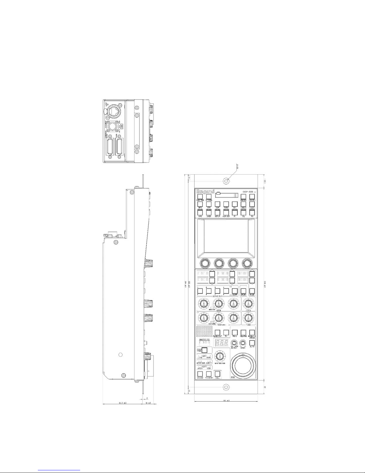
1.3 External view
1) VR TYPE
1. Overview 1-3
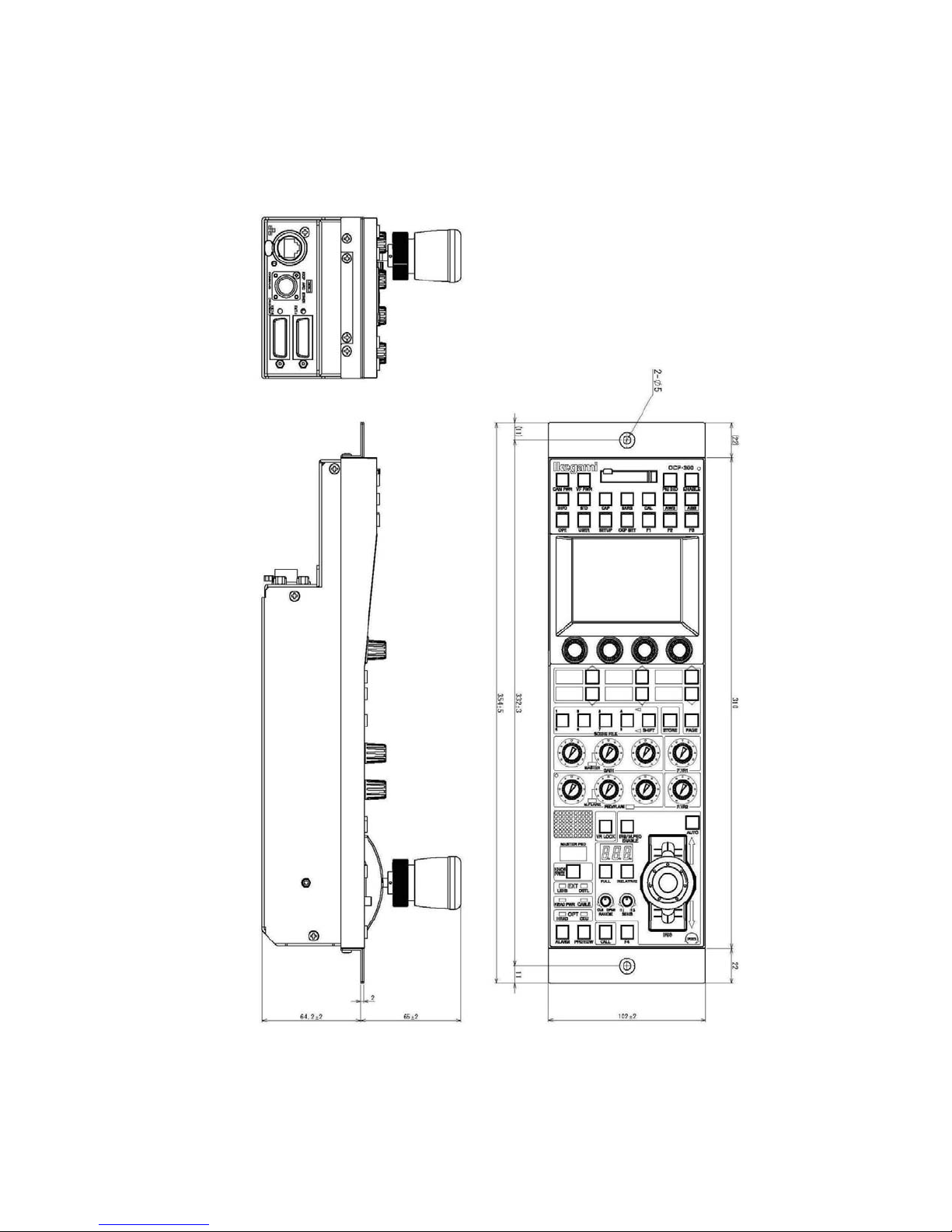
1-4 1. Overview
2) JOYSTICK TYPE
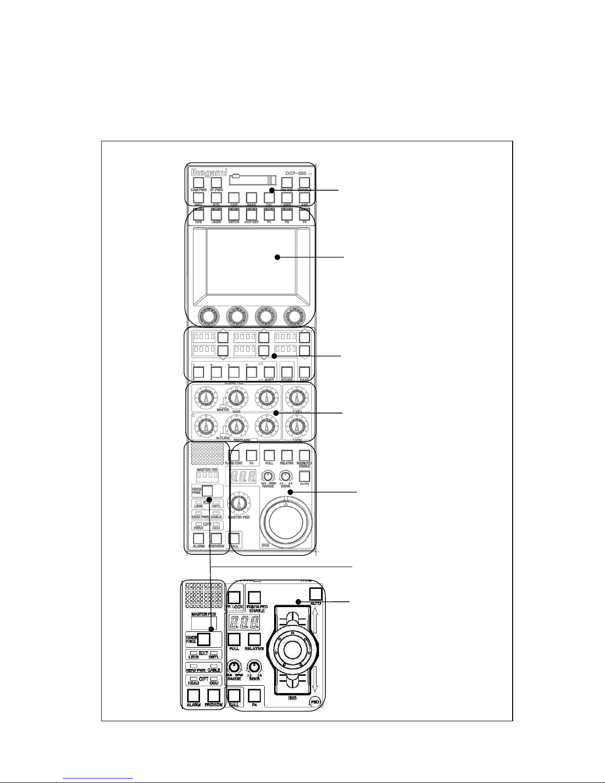
2. The Name and Function of Each Part 2-1
2. The Name and Function of Each Part
Since OCP-300 has many functions, it will be divided and explained according to the blocks.
VR TYPE
1. Camera Function Control Unit
2. LCD Menu-Operations
Part
JOYSTICK
TYPE
3. Selection Function
Control Unit
4. Control Knob
5. Iris/Pedestal Control Section
7. Status Display Part
6. Iris/Pedestal Control Section
2-2 2. The Name and Function of Each Part
ձ
ղ
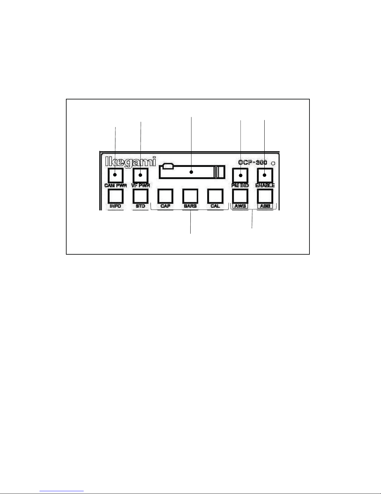
2.1 Camera Function Control Unit
䐟
䐠
㻌
䐡
䐢
䐣
㻌
䐥
䐤
CAM PWR switch
Remote control can perform power transmission from BS/CCU to the camera head by
OCP.
Push the switch, when the power transmission is turned ON from the power
transmission status of OFF (the switch goes out).
When the power transmission is turned OFF from the power transmission status of ON
(the switch lights up), please continue pushing the switch for 2 seconds.
However, the remote control is possible when connecting to BS/CCU(BS-79LP, etc)
which is possible to perform power transmission control to the camera head with
command.
VF PWR switch
Turn ON/OFF the power supply of the view finder (VF). The light is switched on by ON.
When you turn OFF the power supply of the view finder, please continue pushing the
switch for 2 seconds.

2. The Name and Function of Each Part 2-3
ճ
մ
յ
Memory card slot
It is a slot for the memory card (SD card) which performs save and call of the camera
head and the data of BS/CCU.
When you use the memory card, please insert the card into the slot calmly until it will
be locked and not returned. Moreover, when you take out the card, please push the
upper part of the inserted card in calmly. Then, the card can be lifted and pulled out.
When you do not use the memory card, please attach the cover for protection against
dust.
The access indicator beside the slot lights up during write and read operation. Please do
not pull out the card, when the access indicator is on. Not only destruction of the data in
the card is caused but the camera head and the data of BS/CCU may be destroyed.
PM IND/PAGE switch
Indicates the variety of information by characters at PM output of BS/CCU.
Whenever the switch is pushed, it displays as follows.
Display OFF
Page 0 .......... Camera ID display screen
Page 1 .......... Self-test information (diagnosis) display screen
Page 2 .......... Auto-setup monitor execution display screen
Page 3 .......... Standby (reserve) screen
(SCENE FILE NAME etc.)
ENABLE switch
Enables operation of OCP.
When the switch is on, the control from OCP becomes possible.

2-4 2. The Name and Function of Each Part
ն
࣭CAP switch
࣭BARS switch
࣭CAL switch
շ
MODE switch
AWB/ABB switch
Performs AWB (automatic white balance) or ABB (auto black balance).
When the execution is completed, the lamp goes out, and when it is NG, it blinks. If NG
is confirmed, please push again the blinking switch, and cancel NG status.
In addition, the execution of Quick Auto Setup/Auto Black Shade is possible by long
push of the AWB switch/the ABB switch, respectively.
Caution
Sets the optical filter in the CAP position and makes the iris of the lens closed.
Makes the video output signals the color bar signals.
Inputs 100% or 200% of the CAL signal into the graphic processing of the camera
head.
If the switch is pushed, it will change in order of CAL OFF (putting out lights)
->CAL100% (lighting) -> CAL200% (blink) -> CAL OFF (putting out lights). Moreover,
the guard by long push can also be done to CAL200%.
Caution㸸Depending on the setup of the camera and panel config, it may not operate by
long push.

ձ
2.2 LCD Menu-Operations Part
䐡
䐟
2. The Name and Function of Each Part 2-5
䐠
䐢
FUNCTION switch
It is a function selection switch of the LCD menu.
࣭INFO switch
Displays information, such as the camera head and the ON/OFF setting state of
BS/CCU on the LCD.
࣭OPE switch
Lets the LCD menu be in the mode suitable for operation.
࣭SETUP switch
Displays the item in connection with camera adjustment on the LCD menu.
࣭OCP SET switch
Displays the setting item of OCP on the LCD menu.

2-6 2. The Name and Function of Each Part
ղ
ճ
մ
࣭USER switch
Displays the selection switch which the user has set on the LCD. By registering the
switch in advance, it can be called with this switch.
࣭STD switch
Returns the camera head and the data of BS/CCU to the standard setup. If the switch
is pushed, the LCD menu will be displayed and it will be operated by the touch panel.
Reference : Refer to "13. The Standard Function" for the details of operation.
F1, F2, F3, F4 switches
Displays the screen which the user has set on the LCD. By registering the screen into
each switch in advance, it can be called with these switches.
Reference : F4 switch is in "2.5 Iris/Pedestal Control Section (VR TYPE)" and "2.6
Iris/Pedestal Control Section (JOYSTICK TYPE)."
LCD touch panel
It is a control panel in which the 5-inch LCD panel and the touch switch are combined.
It has the display function which displays the status of the camera and the switch
function which operates the camera. Used for operating various setup.
Reference : Please refer to "4. LCD Menu" for the method of detailed operation.
Rotary encoder knob
Performs various setups, when displaying a function on the LCD.
2.3 Selection Function Control Unit
ձ
࣭ND
࣭CC
࣭Gain :
࣭EFF
࣭Gamm :
࣭Bkst :
࣭AWB
䐟
䐠
2. The Name and Function of Each Part 2-7
䐡
SELECT switch, PAGE switch
Selects each mode with the switch.
(When H is shown on the head, it is a setup of the camera head)
When the number of optical filter turrets is one, it is displayed as "Fltr."
Since ND, CC and EFF have an option on the camera head side
has gone out, selection from OCP cannot be performed. When the camera head has an
option
the camera head side.
: Change of ND filter position
: Change of CC filter position
Change of Step GAIN of the camera head
Usually, set it to "0 dB."
: Change of the EFFECT filter position
Change of the GAMMA STEP of the camera head
Usually, set it to "0.45."
Change of the black stretch/pressing action
࣭Black stretch: +3, +5, +7, +9, +11%
࣭Black press: -3, -5, -7, -9, -11%
The range which can be set up changes with the camera to connect.
Usually, set it to "OFF."
: Change of the AWB memory (Ach/Bch/OFF)
or if the switch is pushed, the option can be moved to the OCP side from
when the switch

2-8 2. The Name and Function of Each Part
࣭Lighting
࣭Putting out lights
࣭Blink
ղ
ճ
Moreover, when OCP has an option or , if long push is done on the switch, the
switch will blink. If the switch is pushed for about 1 second after blinking, the confirm
call sounds and the option can be moved from the OCP side to the camera head.
Status of the switch
As the initial state, the change of ND/CC/Gain is arranged on page 1, EFF/Gamm/Bkst
on page 2 and the AWB channel on page 3, and the change of the page is performed by
the PAGE switch.
By pushing the PAGE switch while pushing the KNOB FREE switch, you can also
return to the front page.
Moreover, the composition for every page can be changed arbitrarily and can be created
up to page 5.
Reference : Please refer to "21.2.1 UP/DOWN SEL" for the change of the composition
: since the option is on the OCP side, the change of OCP to the
: if long push is done when the option is on the OCP side, it will
of each page.
of ND, CC and EFF
filter position is possible.
: since the option is on the camera head side, the change of OCP
to the filter position is impossible.
sound. If it is pushed for about 1 second from the wink start,
the option will move to the camera head side.
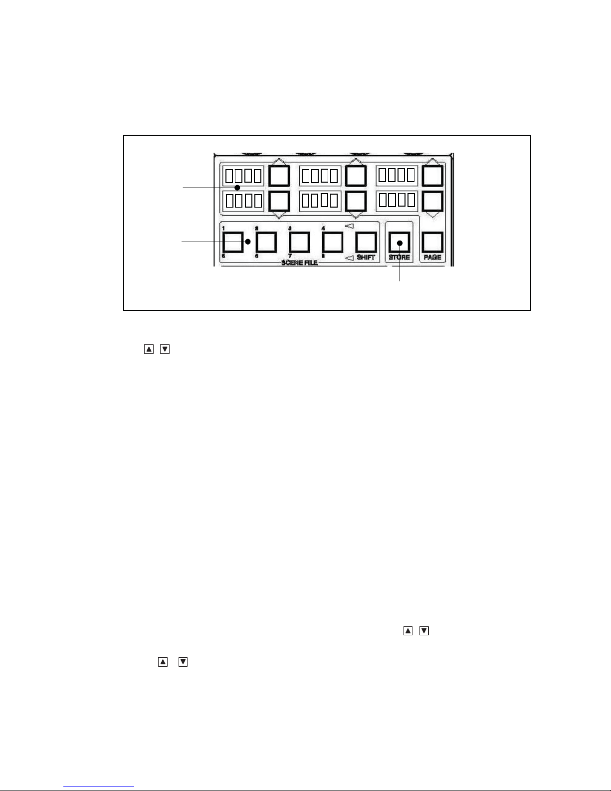
SCENE FILE switch
Reads the scene files 1-8. Changes the files No.1 - No.4, and the files No.5 - No.8 with
the SHIFT switch. The read-out can read the scene file, if the switch of the file number
to read is pushed.
Caution : Conventionally, there was a function made not to feel after the scene file
read-out until the control knob is moved to the center position. Since
OCP-300 differs in the disposal method of the control knob, it does not
commit the function. After the scene file read-out, please use the knob free
function in returning the control knob to the center.
STORE switch
Sets up the scene files 1-8. If the switch of the SCENE FILE number to set up is pushed
in the status that the STORE switch is pushed and the switch is made to turn on, the
setup will be completed and the STORE switch will go out.
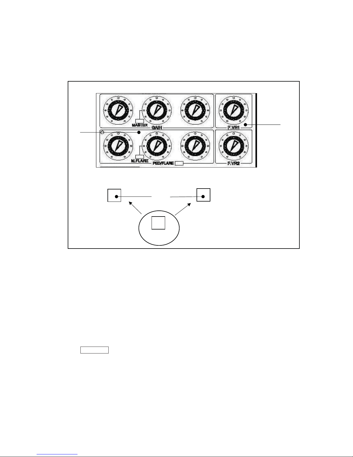
2.4 Control Knob Part
ձ
࣭R/G/B GAIN control knob
ձ
VR TYPE
FLARE CONT
ճ
FLARE CONT
2. The Name and Function of Each Part 2-9
ղ
JOYSTICK TYPE
VR LOCK
Control knob
Controls the gain of Red, Green and Blue channels.
The Green gain serves as operation replaced with R and B.
The control knob of the Green gain is controllable also as the master gain.
When the knob of the Green channel is set as the master gain, the MASTER
indicator lights up.
The change of the master gain and G gain can be performed by the panel config
(setup of the panel).
Reference : Please refer to "21.1.3. Setting Item" for the change of the master gain
and G gain.

2-10 2. The Name and Function of Each Part
࣭R/G/B PED/FLARE control knob
ղ
F VR1 and F VR2,
ճ
մ
Controls the pedestal or the flare of the Red, Green and Blue channels.
The FLARE CONT switch (VR TYPE) or VR LOCK switch (JOY/RE TYPE) of (3)
performs the change of the pedestal and flare.
When the knob of the Green channel is set as the master flare, the M.FLARE
indicator lights up.
In addition, the change of the master flare and G flare can be performed by the panel
config (setup of the panel). Moreover, it becomes the master flare when it is
connected with the camera having the master flare and G flare when it is connected
with the camera not having the master flare when the auto setup is carried out.
Reference : Please refer to "21.1.3. Setting Item" for the change of the master flare
and G flare.
FUNCTION volume
The functions of the USER setup can be given to F
Reference : Refer to "21.2.3 FUNCTION VR" for how to assign a function.
respectively.
FLARE CONT switch (VR TYPE)
Switch whether the R/G/B PED/FLARE control knob is set as the control of the pedestal
or it is set as the control of the flare. When it is flare control, PED/FLARE LED and this
switch light up.
VR LOCK switch (JOYSTICK TYPE)
When this switch is pushed and turned ON, prohibition starts on each control knob of
ձ and ղ and it does not operate even if turned. Moreover, when it is turned OFF from
ON, prohibition of the control knob is canceled (without jumping of the controlled
variable regardless of the position of the control knob).
Moreover, it can be switched by pushing this switch while pushing the KNOB FREE
switch whether the R/G/B PED/FLARE control knob is set as the control of the pedestal
or it is set as the control of the flare. When it is the flare control, LED lights up.
 Loading...