

Ikegami OCP-100 Operation Manual
CAM
HEAD
POWER
POWER
HEAD
COLOR
MASTER
CCU
LINK
OPT LEVEL
ENG FILE
SKIN HUE QUICK START A WB ABB
LOAD
AUTO SETUP
BARS
CAP
CAL SUPER V
SOFT
SKIN
DTL
DTL
ON VAR.
VAR.
SHUTTER
MODE SWITCH
54321
ND EFFCC
FILTER
1234
5678
SCENE FILE
VAR.
GAMMADTL KNEE PT. SLOPE
C.TEMP
COLOR
VAR.
M. GAIN
SAT
C.TEMP
CONT
GAIN
PED FLARE
BLACK
TALLY
BRGB
LENS EXT
G
Y
ENCR
KNOB FREE
MON SEL
OPEN
CLS
±1 ±2
FULL
RANGE SENS
IRIS
CABLE
OPEN SHORT
ALARM CALL
-
OCP
VF
PANEL
POWER
ENABLE
ON
/
PAGE
PM IND
HOLD MENU
123 L HM
SUPER KNEE
MATRIX
+3++
37113711
F2F1
(%)
ON
BLK STRETCH
GAMMA
dB
GAIN
HEAD
EDCBA
STORE
COLOR
SAT
AUTO
VR CLR
LOCK
KNEE
MASTER
FLARE
AUTO
IRIS
PED
100
OCP-100
OPERATION CONTROL PANEL
OPERATION MANUAL
1209 1nd Edition (U) (E)
Copyright©2004IkegamiTsushinkiCo.,Ltd.
Copyright © 2004 Ikegami Tsushinki Co., Ltd.
We reserve the copyright on the software we create.
Nopartofthispublicationmaybemodifiedorreproducedinanyform,orbyanymeans,withoutpriorwrittenpermissionfrom
Ikegami Tsushinki Co., Ltd.
We reserve the copyright on the software we create.
No part of this publication may be modifi ed or reproduced in any form, or by any means, without prior written permission from
Ikegami Tsushinki Co., Ltd.

G
N
SAFETY PRECAUTIONS i
SAFETY PRECAUTIONS
The safety precautions for using this product are described below. Please read them thoroughly before use.
1. Safety Alert Symbols
This manual employs the following “Safety Alert Symbols” to call attention to hazards:
WARNIN
CAUTIO
: 㩷Indicates that mishandling of the product may lead to a danger resulting in a serious injury or
death.
: Indicates that mishandling of the product may lead to a danger resulting in an injury or
property damage.
2. Handling Precautions
This product is designed with safety in mind; however, any electrical equipment may cause electric shock or equipment
damage if used in an inappropriate manner or under unsuitable conditions.
Therefore, please follow the following instructions when handling this product:
(1) Do not remove the covers or disassemble unless absolutely necessary, to prevent malfunction or electric shock.
(2) Do not drop or expose the equipment to a strong vibration or shock.
A strong vibration or shock may cause equipment damage or failure.
(3) Be sure to turn OFF the power switch before removing modules.
(4) Avoid using or storing in the following conditions. It may cause damage to the product.
- Extremely high/low temperature
- High humidity or dusty
- Exposed to water or other liquid
- Strong vibration or shock
- Strong magnetic fi eld or radio waves
- lightning
- In rain or snow without the cover
(5) When carrying or storing the product, always use a carrying case.
(6) Be sure to hold the plug and pull when disconnecting the cable. Failure to do so may cause a fi re or electric shock due to a
broken cable.
(7) Do not drop or insert metal objects such as clips or foreign objects into the equipment.
(8) Do not spread or spill water or other liquid on the equipment.
(9) Regarding the lithium battery
- Do not use an unspecifi ed battery.
- Wrong usage of batteries may cause liquid leak, explosion, and heat, and at worst injury or fi re. When replacing or
discarding a battery, please contact Ikegami's sales and service centers.
3. Regular Maintenance Recommended
This product includes parts that wear out and have a limited life even in proper use or storage. Therefore, regular maintenance
(once every 3 years or 8000 hours use) is recommended to extend the life and safe use of this product for a long time.
Please contact Ikegami's sales and service centers or Techno Ikegami Co., Ltd. for the regular maintenance and repair of our
products.
OCP-100 1209 VOL1 (U) (E) OCP-100

ii HOW TO USE OPERATION MANUAL
HOW TO USE OPERATION MANUAL
The OCP-100 OPERATION CONTROL PANEL OPERATION MANUAL is intended to describe how to operate the OCP-100.
This manual is written for readers with a basic knowledge of handling broadcast cameras and Base Station (BS), so technical terms
are not explained here.
This manual consists of fi ve chapters. Related topics are included in the same chapter as much as possible so that you do not have to
turn pages back and forth.
Each chapter is arranged in the order of actual operating procedures. By reading it in sequence, you can smoothly perform a series of
steps, from installation and connection to operation in a proper manner.
[Structure of Operation Manual]
1. NAME and FUNCTION
: Explains the name and function of each switch and control on the OCP-100.
2. INSTALLATION and CONNECTION
3. OPERATION
4. TROUBLESHOOTING
5. SPECIFICATIONS
: Explains how to turn on power, how to check operation, and how to activate
: Explains self-diagnosis function.
: Lists the specifi cations and external dimensions of the OCP-100.
: Explains how to connect the OCP-100 to the camera or BS. Also explains the
specifi cations of connector pins.
various functions.
[Symbols]
The symbols used in this manual are as follows:
Note:
Reference:
Supplementary information on the matter just discussed
Sections or pages where related information is available
[Reference Manuals]
- HK-399PW COLOR CAMERA MAINTENANCE MANUAL
- HK-399PW COLOR CAMERA OPERATION MANUAL
- BS-388 BASE STATION INSTRUCTION MANUAL
OCP-100 OCP-100 1209 VOL1 (U) (E)

OCP-100
F KEY customized function
OPERATION CONTROL PANEL
OPERATION MANUAL
CONTENTS iii
SAFETY PRECAUTIONS
HOW TO USE OPERATION MANUAL
. . . . . . . . . . . . . . . . . . . . . . . . . . . . . . . . . . . . . . . . . . . . . . . . . . . . . . . . . . . . . . . . . . . . . . . . . . . . . . . . . . . .
. . . . . . . . . . . . . . . . . . . . . . . . . . . . . . . . . . . . . . . . . . . . . . . . . . . . . . . . . . . . . . . . . . . . . . . . .
1. NAME and FUNCTION. . . . . . . . . . . . . . . . . . . . . . . . . . . . . . . . . . . . . . . . . . . . . . . . . . . . . . 1-1
2. INSTALLATION and CONNECTION . . . . . . . . . . . . . . . . . . . . . . . . . . . . . . . . . . . . . . . . . . . 2-1
2.1 OCP Connection . . . . . . . . . . . . . . . . . . . . . . . . . . . . . . . . . . . . . . . . . . . . . . . . . . . . . . . . . . . . . . . 2-1
2.2 Connector Pin Function . . . . . . . . . . . . . . . . . . . . . . . . . . . . . . . . . . . . . . . . . . . . . . . . . . . . . . . . . 2-3
3. OPERATION . . . . . . . . . . . . . . . . . . . . . . . . . . . . . . . . . . . . . . . . . . . . . . . . . . . . . . . . . . . . . . 3-1
3.1 Turning ON Power . . . . . . . . . . . . . . . . . . . . . . . . . . . . . . . . . . . . . . . . . . . . . . . . . . . . . . . . . . . . . . 3-1
3.1.1 Non-POWER CONT . . . . . . . . . . . . . . . . . . . . . . . . . . . . . . . . . . . . . . . . . . . . . . . . . . . . . . . . . . . . . . . . .3-1
3.1.2 POWER CONT . . . . . . . . . . . . . . . . . . . . . . . . . . . . . . . . . . . . . . . . . . . . . . . . . . . . . . . . . . . . . . . . . . . . . 3-1
3.2 Operation Check . . . . . . . . . . . . . . . . . . . . . . . . . . . . . . . . . . . . . . . . . . . . . . . . . . . . . . . . . . . . . . . 3-2
3.2.1 Checking Color Bars Signal . . . . . . . . . . . . . . . . . . . . . . . . . . . . . . . . . . . . . . . . . . . . . . . . . . . . . . . . . . . 3-2
3.2.2 Checking with CAL Pulse . . . . . . . . . . . . . . . . . . . . . . . . . . . . . . . . . . . . . . . . . . . . . . . . . . . . . . . . . . . . .3-3
3.2.3 Checking Images on Charts . . . . . . . . . . . . . . . . . . . . . . . . . . . . . . . . . . . . . . . . . . . . . . . . . . . . . . . . . . .3-3
3.3 Auto Setup . . . . . . . . . . . . . . . . . . . . . . . . . . . . . . . . . . . . . . . . . . . . . . . . . . . . . . . . . . . . . . . . . . . 3-4
3.3.1 Quick Auto Setup . . . . . . . . . . . . . . . . . . . . . . . . . . . . . . . . . . . . . . . . . . . . . . . . . . . . . . . . . . . . . . . . . . .3-5
3.3.2 AWB (Auto White Balance) . . . . . . . . . . . . . . . . . . . . . . . . . . . . . . . . . . . . . . . . . . . . . . . . . . . . . . . . . . . .3-6
3.3.3 ABB (Auto Black Balance) . . . . . . . . . . . . . . . . . . . . . . . . . . . . . . . . . . . . . . . . . . . . . . . . . . . . . . . . . . . . 3-7
3.4 Operation Procedures . . . . . . . . . . . . . . . . . . . . . . . . . . . . . . . . . . . . . . . . . . . . . . . . . . . . . . . . . . . 3-8
3.4.1 Correcting Color Temperature for Multiple Cameras (Color Link) . . . . . . . . . . . . . . . . . . . . . . . . . . . . . .3-8
F KEY customized function . . . . . . . . . . . . . . . . . . . . . . . . . . . . . . . . . . . . . . . . . . . . . . . . . . . . . . . . . . . 3-10
3.4.2
3.5 Menu Remote . . . . . . . . . . . . . . . . . . . . . . . . . . . . . . . . . . . . . . . . . . . . . . . . . . . . . . . . . . . . . . . . 3-12
3.6 Panel Confi g function . . . . . . . . . . . . . . . . . . . . . . . . . . . . . . . . . . . . . . . . . . . . . . . . . . . . . . . . . . 3-13
i
ii
4. TROUBLESHOOTING . . . . . . . . . . . . . . . . . . . . . . . . . . . . . . . . . . . . . . . . . . . . . . . . . . . . . . 4-1
5. SPECIFICATIONS . . . . . . . . . . . . . . . . . . . . . . . . . . . . . . . . . . . . . . . . . . . . . . . . . . . . . . . . . . 5-1
5.1 Rating . . . . . . . . . . . . . . . . . . . . . . . . . . . . . . . . . . . . . . . . . . . . . . . . . . . . . . . . . . . . . . . . . . . . . . . 5-1
5.2 Control Conditions . . . . . . . . . . . . . . . . . . . . . . . . . . . . . . . . . . . . . . . . . . . . . . . . . . . . . . . . . . . . . 5-1
5.3 Environmental Conditions . . . . . . . . . . . . . . . . . . . . . . . . . . . . . . . . . . . . . . . . . . . . . . . . . . . . . . . . 5-1
5.4 External Dimension Diagram . . . . . . . . . . . . . . . . . . . . . . . . . . . . . . . . . . . . . . . . . . . . . . . . . . . . . 5-3
OCP-100 1209 VOL1 (U) (E) OCP-100

iv CONTENTS
OCP-100 OCP-100 1209 VOL1 (U) (E)
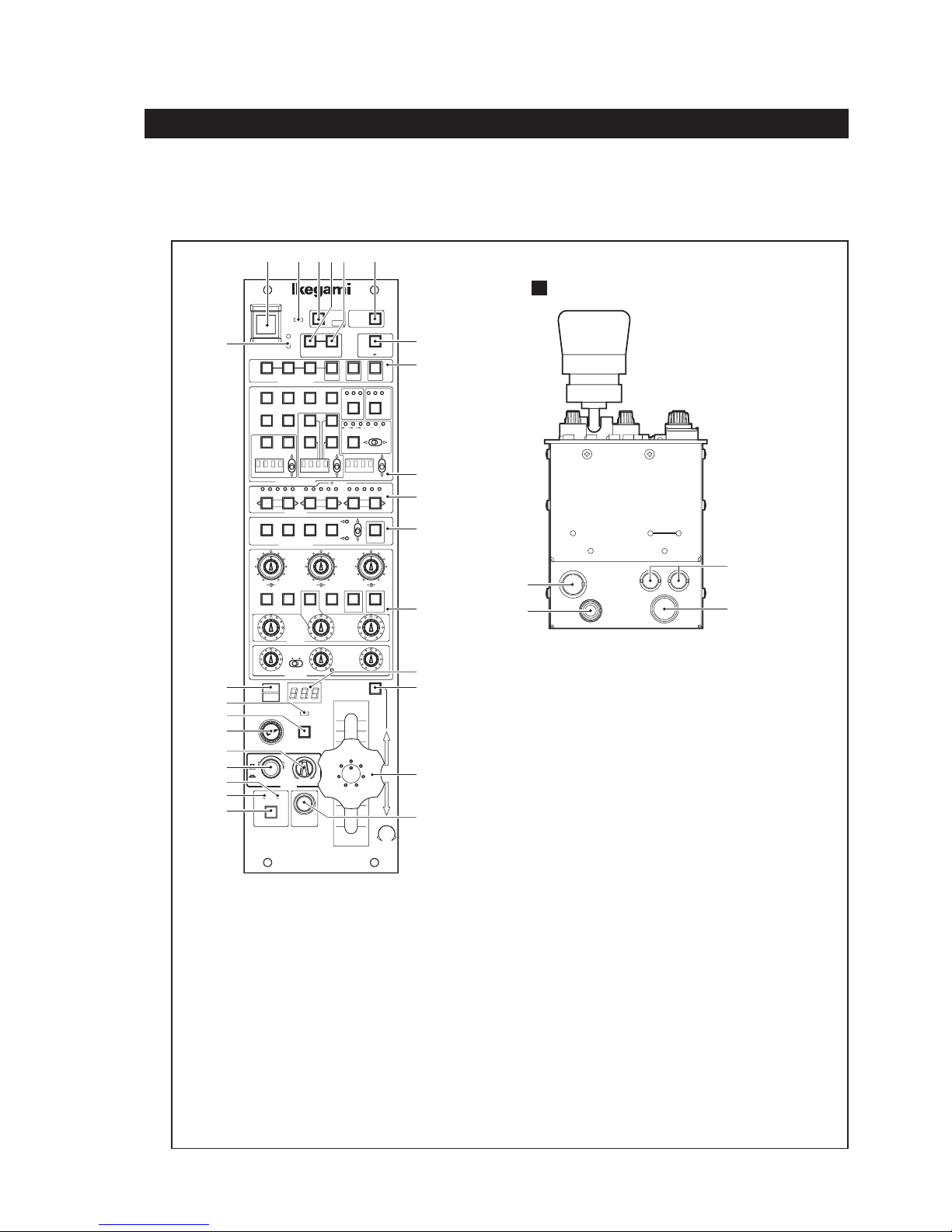
1. NAME and FUNCTION
The diagrams below show the locations of switches and connectors.
Note:
The switches and VR controls on the OCP do not work if the connected camera does not have corresponding functions.
Refer to the manual for the connected camera for available functions.
1 2 3 654
VF
PANEL
POWER
ENABLE
ON
7
/
PAGE
PM IND
MASTER
GAMMA
COLOR
AUTO
KNEE
F2F1
SAT
HEAD
EDCBA
HOLD MENU
123 L HM
MATRIX
37113711
ON
BLK STRETCH
(dB)
GAIN
VR CLR
SUPER KNEE
+3++
(%)
STORE
LOCK
8
9
10
11
12
LINK
VAR.
CONT
22
CAM
HEAD
POWER
POWER
HEAD
COLOR
CCU
OPT LEVEL
ENG FILE
SKIN HUE QUICK START AWB ABB
LOAD
AUTO SETUP
CAP BARS CAL SUPER V
SOFT
SKIN
DTL
DTL
ON VAR.
C.TEMP
SHUTTER
MODE SWITCH
54321
ND EFFCC
FILTER
1234
5678
SCENE FILE
VAR.
GAMMADTL KNEE PT. SLOPE
C.TEMP
COLOR
VAR.
M. GAIN
SAT
C.TEMP
27
30
Rear View
P.S CONT
PREVIEW
1. NAME and FUNCTION 1-1
COLOR LINK
COMM
28
29
GAIN
PED FLARE
BLACK
26
25
24
23
21
20
19
18
17
TALLY
B RGB
G
Y
ENCR
MON SEL
OPEN
CLS
FULL
RANGE SENS
IRIS
CABLE
OPEN SHORT
ALARM CALL
1
CAM POWER switch
2
HEAD POWER indicator
3
VF POWER switch
4
COLOR LINK switch
5
MASTER switch
6
PANEL ENABLE switch
7
PM IND/PAGE switch
8
AUTO SETUP switches
9
MODE switches
10
FILTER switches
11
SCENE FILE switches
12
MODE switches/VR controls
13
IRIS indicator
14
AUTO IRIS switch
15
JOYSTICK (IRIS, M-PED) (PREVIEW switch)
LENS EXT
KNOB FREE
±1 ±2
OCP
MASTER
FLARE
AUTO
IRIS
13
14
15
16
PED
-
100
16
CALL switch
17
ALARM indicator
18
CABLE OPEN indicator
19
CABEL SHORT indicator
20
IRIS RANGE control
21
IRIS SENS control
22
OPT LEVEL indicators
23
MONITOR SELECT switch
24
KNOB FREE switch
25
LENS EXT indicator
26
TALLY indicators
27
PS CONT connector
28
COLOR LINK connectors
29
COMMAND connector
30
PREVIEW connector
OCP-100 1209 VOL1 (U) (E) OCP-100

1-2 1. NAME and FUNCTION
1 CAM POWER switch
When used with a BS/CCU which does not support the Power Cont cable, the Camera Head power output can be turned ON/
OFF.
Note:
When BS/CCU compatible with POWER CONT is connected, the MAIN POWER can be remotely controlled if the
POWER REMOVE/LOCAL switch of BS/CCU is set to REMOTE.
2 HEAD POWER indicator
Lights when the HEAD POWER is ON. Flashes when the camera cable is faulty (OPEN, SHORT).
3 VF POWER switch
Turns ON/OFF the power supply of the VF. When turning OFF the power supply of the VF, press the switch continuously for
two seconds.
Note:
This switch is valid only if the camera head has the VF power ON/OFF function.
4 COLOR LINK switch
When pressed, the camera is changed from the master camera to the slave camera to receive color link information. (Refer to
the MASTER switch.)
Reference:
Refer to“ 3.4.1 Correcting Color Temperature for Multiple Cameras (Color Link)” for details.
5 MASTER switch
When pressed with the COLOR LINK switch ON, the camera is changed to the master camera to transfer color link
information to other cameras. (Refer to the COLOR LINK switch.)
Reference:
Refer to“ 3.4.1 Correcting Color Temperature for Multiple Cameras (Color Link)” for details.
6 PANEL ENABLE switch
Enables operations of the OCP.
7 PM IND/ PAGE switch
Displays various information in character format to the PM output of the BS. The information is displayed as shown below
each time the switch is pressed.
Display
Page
Page
Page
OFF
.....................
0
.....................
1
.....................
2
Cameraman's name display
Self-diagnostic information display
Auto setup monitor display
Page
When the PM IND/PAGE switch is held for more than 1 second, the mode is changed to menu remote mode, and the menu of
the camera or BS can be controlled from the OCP. Refer to “3.5 Menu Remote” for details.
OCP-100 OCP-100 1209 VOL1 (U) (E)
.....................
3
Scene Files display

1. NAME and FUNCTION 1-3
8 AUTO SETUP switches
- SKIN HUE switch, QUICK switch, START switch
When the START switch is pressed after pressing the SKIN HUE or QUICK switch, the respective auto setup process will
be executed. Pressing the switch again while executing auto setup will cancel the execution. When the execution ends, the
lamp goes OFF. When the execution fails, the START switch fl ashes. After confi rming the failure, press the START switch
again to clear the failure.
- AWB switch, ABB switch
Used to execute the AWB (auto white balance) or ABB (auto black balance). When the execution ends, the lamp goes OFF.
When the execution fails, the lamp fl ashes. After confi rming the failure, press the fl ashing switch again to clear the failure.
- ENG FILE LOAD switch
Press the ENG FILE LOAD switch fi rst, and then press the START switch. The Engineer File 1 is loaded at the HEAD side,
and then the unit is restarted.
9 MODE switches
- CAP switch
Used to set the fi lter to the CAP position. Or close the Iris on camera models which do not have a Cap fi lter.
- BARS switch
Used to set the output signal to the color bar signal.
- CAL switch
Inputs the 100% level CAL signal in the camera head. When the CAL PULSE switch is turned ON by MCP, the lamp of the
CAL switch fl ashes.
- SOFT DTL switch
When set to ON, the edge signal is input to the level limiter circuit to control the maximum edging of subjects with large
contrast ratio.
- SKIN DTL switch
When set to ON, the DTL in theskin color of the image is reduced to the optimum level. This does not affect the DTL in
other colors.
- MATRIX switch
Used to select one of the three preset MATRIX settings (1, 2, or 3) or OFF. The LED above the switch indicates the current
preset setting. When it is set to OFF, the switch lamp goes off. Each time the switch is pressed, 1, 2, 3, or OFF is selected in
that order repeatedly. Normally, set to “1”. The three preset values are previously set by the MCP.
- SUPER KNEE switch
Used to set SUPER KNEE to ON. One of the three SUPER KNEE levels (L, M, or H) can be selected. “H” produces the
largest effect, “M” the next, and “L” the smallest effect. The LED above the switch indicates the current setting. When it is
set to OFF, the switch lamp goes off. Each time the switch is pressed, L, M, H, or OFF is selected in that order repeatedly.
Normally, set to “M”.
- F KEY switch, VAR C.Temp switch, GAMMA switch
When one of the F1, the F2, the VAR C.Temp or the GAMMA switch is set to “ON”, the status of the item concerned will
appear on the Display at the center. The function setting value can be changed by using the
the F1 and the F2 switches are set to “ON”, the name of the function that has been registered will be displayed for about 1
second, and then the status value will be displayed.
UP/DOWN switch. When
- BLK STRETCH switch
Used to select the black stretch/press settings. Press the “ON” switch and then the
following positions can be selected:
Black stretch : +3, +5, +7, +9, +11
Black press : -11, -9, -7, -5, -3
The LED indicates the current setting. When LEDs for ±11 and ±7 light simultaneously, it indicates ±9. Similarly, when
LEDs for ±7 and ±3 light simultaneously, it indicates ±5.
OCP-100 1209 VOL1 (U) (E) OCP-100
UP/DOWN switch. Any of the
1-4 1. NAME and FUNCTION
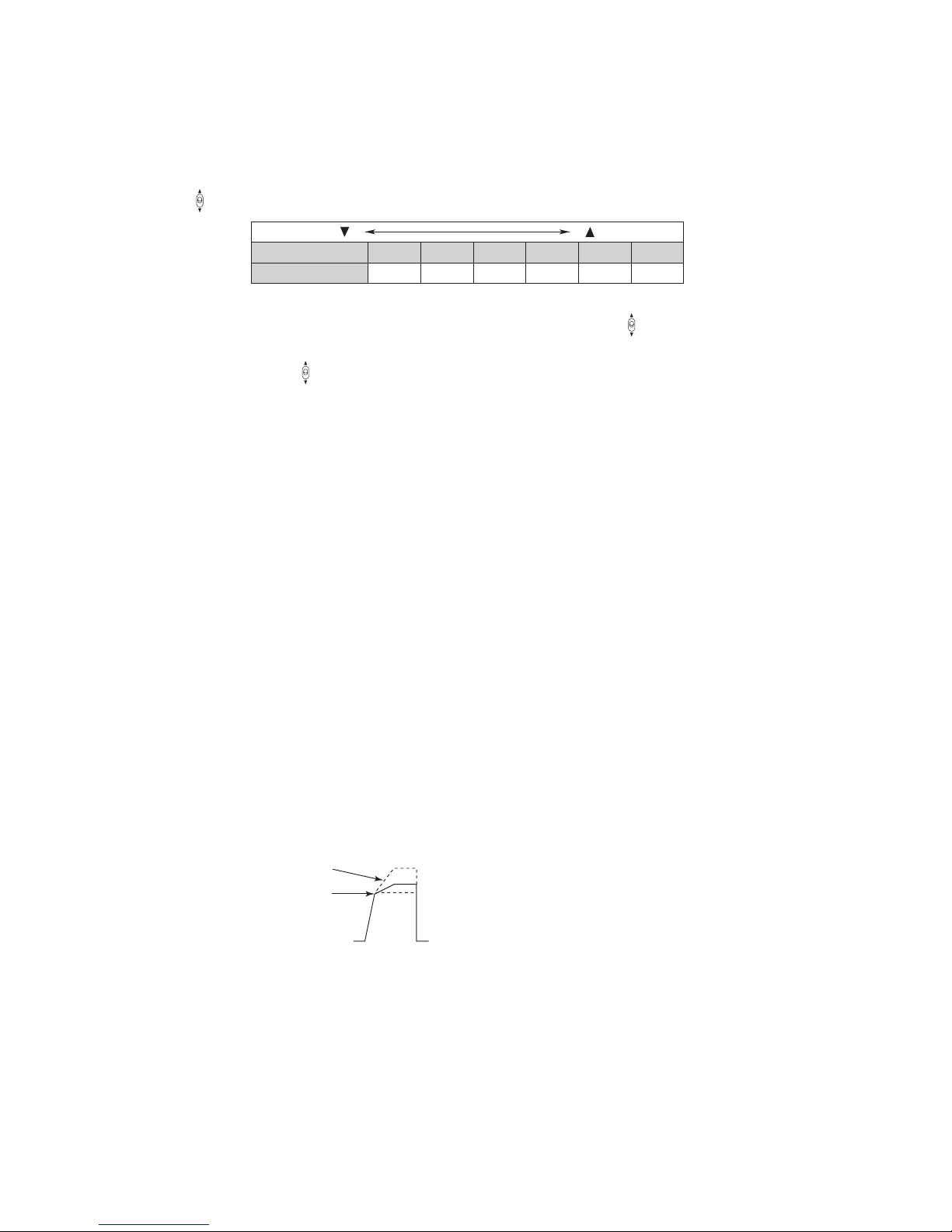
- SHUTTER switches
When the SHUTTER ON/OFF switch is pressed, the lamp lights and the preset shutter mode is set and the electronic
shutter starts working. When the switch is pressed again, the lamp goes off and the electronic shutter also stops operating.
While the electronic shutter is operating, the shutter speed will be displayed on the LED display. Select the shutter speed
using the
UP/DOWN switches.
DOWN
LED Display
Shutter Speed
100 120 250 500 1000 2000
1/100 sec 1/120 sec 1/250 sec 1/500 sec 1/1000 sec 1/2000 sec
UP
Pressing the VARIABLE SHUTTER switch sets the variable shutter mode. The VARIABLE indicator lights up and the
shutter speed is displayed on the LED display. The shutter speed can be selected using the
UP/DOWN switches.
- GAIN switch
Select Master Gain using the
+24, +20, +36, +42, or +48dB. The LED display indicates the current Gain setting value. Normally, set to “0”.
Note:
The range of conf igurable gains varies, depending on the type of the connected camera.
UP/DOWN switch. One of the following values can be selected: -3, 0, +3, +6, +9, +12, +18,
10 FILTER switches
Use the switches to select a position of each fi lter. When the HEAD indicator is on, it indicates that the camera head is has
control, and control from the OCP is disabled. If the switch is pressed in this mode, the switch lamp starts fl a shi ng. Pre ssi ng
both fl ashing switches simultaneously shifts control from the camera head to the OCP. To shift control from the OCP to the
camera head, also press both switches simultaneously.
11 SCENE FILE switches
Sets and reads scene fi les 1 to 8. Files No. 1 to No. 4 and No. 5 to No. 8 can be switched by the toggle switch on the left of the
STORE switch.
Set : Press the STORE switch, and then press the fi le number (1 to 8) to be set.
Read : Press the fi le number to be read.
12 MODE switches/VR controls
- DTL/GAMMA controls
Used to control the DTL and GAMMA levels.
- VAR C. TEMP/COLOR SAT controls
Used to control the VAR. C. TEMP and COLOR SAT levels.
- KNEE POINT/SLOPE controls
Used to control the KNEE SLOPE and POINT manually.
SLOPE
POINT
- COLOR SAT switch
Used to turn ON/OFF the color saturation control.
- M. GAIN CONT switch
This is a switch for setting the Analog G GAIN control to master gain or to G gain. By setting the switch to “ON”, the
master gain is selected, or by setting it to “OFF”, the G gain is selected.
- AUTO KNEE switch
Used to set the AUTO KNEE mode.
OCP-100 OCP-100 1209 VOL1 (U) (E)

1. NAME and FUNCTION 1-5
- VR CLR switch
This clears setting values of all items and resets them to the reference value. Clearing is carried out by a long press of the
VR CLR switch.
- Item to clear “R/G/B/M FLARE” “R/G/B/M PED” “R/B/TOTAL GAIN”
“KNEE POINT/TOTAL” “AUTO KNEE POINT/TOTAL”
“MASTER GAMMA” “COLOR SAT” “VAR CTEMP”
When R/B GAIN is cleared, the existing VAR C. TEMP ON/OFF setting is also cleared.
- LOCK switch
Use to lock each control (DTL/SKIN, C.SAT/GAMMA, KNEE PT/SLOPE, R GAIN, G GAIN, B GAIN, R BLACK, G
BLACK and B BLACK) in the VR control area. When the LOCK switch lamp is on, you cannot operate these controls.
- R/G/B/M GAIN control
Used to control the gain of R, G, and B channels. Controlling the G gain will not change the actual video signal level of
G channel, but the levels of R and B channels change relatively. This is to prevent the change of camera sensitivity setting
caused by the change of the G channel.
- R/G/B BLACK control
Used to control the pedestal or fl are of R, G, and B channels. Use the PED FLARE switch to select between pedestal and
fl are. If the fl are control is selected, the MASTER FLARE indicator lights when the OCP is connected to a camera which
supports MASTER FLARE, indicating the MASTER FLARE control is active.
- PED FLARE switch
Used to select between pedestal and fl are for the R/G/B BLACK control.
13 IRIS indicator
Displays the F value of the lens. The F value is not displayed (“---” is displayed) when F16 is exceeded to CLOSE.
14 AUTO IRIS switch
Used to set the AUTO IRIS mode.
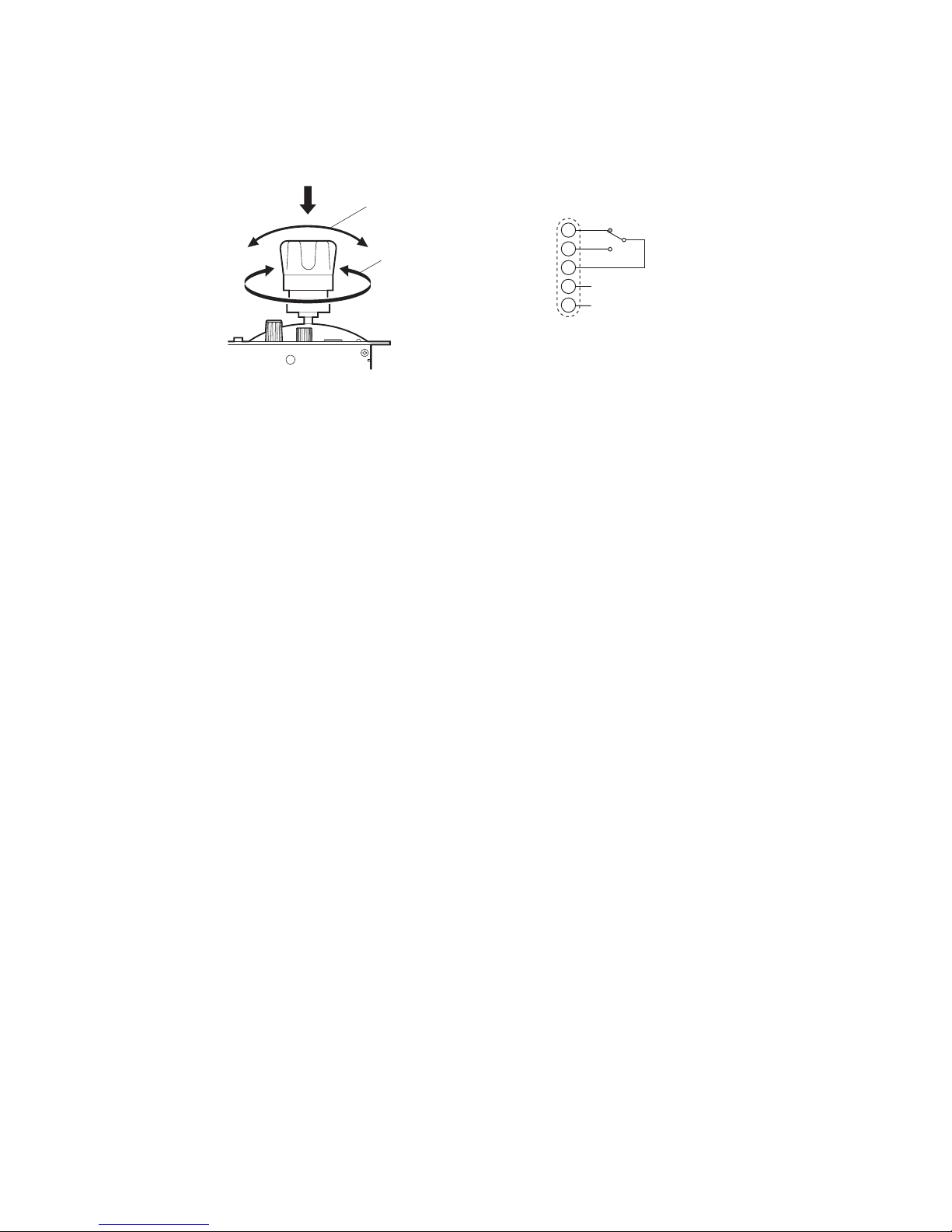
15 JOYSTICK
- IRIS control and M-PED control
Controls the IRIS of the lens and the master pedestal. In AUTO IRIS mode, the iris is controlled with ±1 stop range.
OCP-100 1209 VOL1 (U) (E) OCP-100
1-6 1. NAME and FUNCTION
- PREVIEW switch
By pressing the top of the JOYSTICK, pins B and C of the PREVIEW connector (see item 30) will be short-circuited.
PREVIEW switch
IRIS control
Note:
The operation of JOYSTICK is normally set to the relative value mode. It can be switched to the absolute value mode by
changing the internal switch setting. Refer to“ 3.6 Panel Config function” for how to switch the mode.
A
M-PED control
PREVIEW connector
B
C
D
N.C
E
N.C
Relative value mode : In this mode, when the control is shifted from the MCP to the OCP, the IRIS value that is
adjusted on the MCP is maintained regardless of the position of the IRIS RANGE control
and JOYSTICK to prevent unintentional change of IRIS value. Operation may become onesided depending on the position of the control and JOYSTICK. The one-sided operation can
be corrected by setting the control and JOYSTICK to the center position while holding down
the KNOB FREE button.
(DC5V 1mA)
Absolute value mode : In this mode, the position of the IRIS RANGE control and JOYSTICK directly affects Open
and Close of the IRIS.
16 CALL switch
Lights the R TALLY of the camera head and BS.
17 ALARM indicator
Flashes when an error is detected resulting from the self-diagnosis function. The diagnosis information is automatically
displayed on the PM for about 20 seconds.
18 CABLE OPEN indicator
Lights when the triax or fi ber cable between the camera head and the BS is broken or not connected. This indicator is
interlocked with the CABLE OPEN indicator on the front of the BS.
19 CABLE SHORT indicator
Lights when the triax or fi ber cable between the camera head and the BS is short circuited. This indicator is interlocked with
the CABLE SHORT indicator on the front of the BS.
20 IRIS RANGE control
Used to set the center position of the IRIS CONTROL of the JOYSTICK (see item 15).
21 IRIS SENS control
Used to set the IRIS CONTROL range of the JOYSTICK (see item 15). The F-value between ±1 stop and ±2 stops can be set.
22 OPT LEVEL indicator
When the optical level of the Camera Head and CCU is normal, the GREEN lamp is turned on; at an attenuated level the
ORANGE lamp and at an insuffi cient level the RED lamp is turned on.
OCP-100 OCP-100 1209 VOL1 (U) (E)
 Loading...