

Ikegami OCP-10 Operation Manual
OCP-10
Operation Control Panel
Operation Manual
Products conforming to RoHS directive

OCP-10
Operation Control Panel
Operation Manual
1501 2nd Edition(U) (E)
Products conforming to RoHS directive
Copyright © 2014 – 2015 Ikegami Tsushinki Co., Ltd
We reserve the copyright on the software we create.
No part of this publication may be modified or reproduced in any form, or by any means, without
prior written permission from Ikegami Tsushinki Co., Ltd.

PRODUCTS CONFORMING TO RoHS DIRECTIVE
PRODUCTS CONFORMING TO RoHS DIRECTIVE
Following products described in this manual are products conforming to RoHS directive.
• OCP-10 Operation Control Panel
Products conforming to RoHS directive include products that do not contain specified hazardous
substances such as lead, mercury, cadmium, hexavalent chromium, polybrominated biphenyl
(PBB) and polybrominated diphenyl ether (PBDE) in electrical and electronic equipment
excluding following exemption applications based on the EU directive (Directive 2002/95/EC).
The RoHS directive stands for “the Restriction of the Use of Certain Hazardous
Substances in Electrical and Electronic Equipment” and is one of environmental
directives in Europe. This directive restricts the use of specified hazardous substances
in electrical and electronic equipment.
Followings applications are permitted as exemptions from RoHS directive compliance.
1. Mercury in compact fluorescent lamps not exceeding 5mg per lamp
2. Mercury in straight fluorescent lamps for general purposes not exceeding:
· halophosphate 10mg
· triphosphate with a normal lifetime 5mg
· triphosphate with a long lifetime 8mg
3. Mercury in straight fluorescent lamps for special purposes
4. Mercury in other lamps not specifically mentioned in this Annex
5. Lead in the glass of cathode ray tubes, electronic components and fluorescent tubes
6. Lead as an alloying element in steel containing up to 0.35% lead by weight,
aluminum containing up to 0.4% lead by weight and as a copper alloy containing up
to 4% lead by weight
7. Lead in following items
· Lead in high melting temperature type solders (i.e. tin-lead solder alloys
containing more than 85% lead)
· Lead in solders for servers, storage and storage array systems
· Lead in solders for network infrastructure equipment for switching, signaling,
transmission as well as network management for telecommunication
· Lead in electronic ceramic parts (e.g. piezoelectronic devices)

PRODUCTS CONFORMING TO RoHS DIRECTIVE
8. Cadmium plating except for applications banned under Directive 91/338/EEC
amending Directive 76/769/EEC relating to restrictions on the marketing and use of
certain dangerous substances and preparations
9. Hexavalent chromium as an anti-corrosion of the carbon steel cooling system in
absorption refrigerators
10. Lead used in compliant pin connector systems
11. Lead as a coating material for the thermal conduction module C-ring
12. Lead and cadmium in optical and filter glass
13. Lead in solders consisting of more than two elements for the connection between the
pins and the package of microprocessors with a lead content of more than 80% and
less than 85% by weight
14. Lead in solders to complete a viable electrical connection between semiconductor die
and carrier within integrated circuit Flip Chip packages
15. Decabrominated diphenyl ether (Deca-BDE) in polymeric applications
MAINTENANCE OF PRODUCTS CONFORMING TO RoHS DIRECTIVE
MAINTENANCE OF PRODUCTS CONFORMING TO
RoHS DIRECTIVE
Work with care about followings for maintenance of products conforming to RoHS directive.
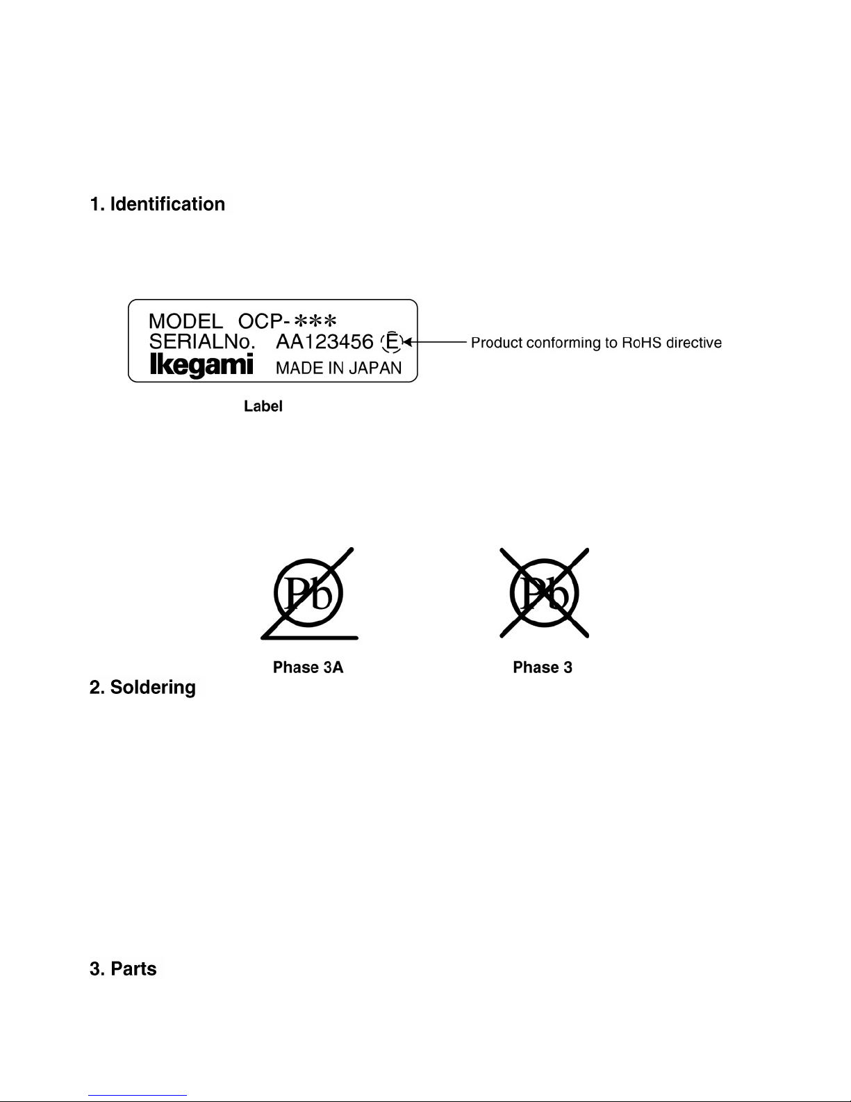
· For products conforming to RoHS directive, the letter “E” is appended at the end of
the serial number on the label. For models that the letter cannot be appended to the
serial number, the letter “E” will be described in a distinguishable position on the
label. A description example on a main label is shown below.
· Print-circuit board of the products conforming to RoHS directive is manufactured by
following methods.
[1] Blue resist ink is used for the print-circuit board. (The color of conventional
print-circuit board is green.)
[2] Either one of the following marks is indicated by a serigraph or label.
Since the melting point of lead-free solder used for the products conforming to RoHS
directive is 20 to 45 degrees Celsius higher than that of conventional solder with lead
(Sn-Pb eutectic solder), a high temperature needs to be set to a soldering iron.
Taking allowable temperature limit of the parts and stable work into consideration,
use a soldering iron with excellent thermal recovery characteristics.
· Recommended solder composition is “Sn/3.0Ag/0.5Cu” or equivalent.
· Separate the soldering iron exclusively for RoHS products and the soldering iron
for conventional use.
· Set the temperature of the soldering bit to 350 to 370 degrees Celsius.
The temperature may need to be adjusted according to the size of the copper foil
land on the print-circuit board and the tip width of the soldering bit.
· Finish by a lead-free solder looks dull or whitish compared to conventional solder with lead.
Be sure to use parts conforming to RoHS directive.

INFORMATION TO THE USER
This equipment has been tested and found to comply with the limits for a Class A
digital device, against harmful interference when the equipment is operated in a
commercial environment. This equipment generates, uses, and can radiate radio
frequency energy and, if not installed and used in accordance with the instruction
manual, may cause harmful interference to radio communications. Operation of this
equipment in a residential area is likely to cause harmful interference in which case the
user will be required to correct the interference at his own expense.
Changes or modifications not expressly approved by the party responsible for
compliance could void the user’s authority to operate the equipment.
The mark means that the following products will meet the Directives 2004/108/EC
and standards EN55032, EN55103- 2 (for the Electromagnetic environment E4-E5).
Use shielded cable.
This equipment doesn’t intend to use at residential areas, so that use in residential
areas may cause interference.
Please attach a core to a cable to connect to a connector of command, Ethernet cable
and EXT by all means. Please make an inquiry to us about the installation of the core, if
necessary.
SAFETY PRECAUTIONS
SAFETY PRECAUTIONS
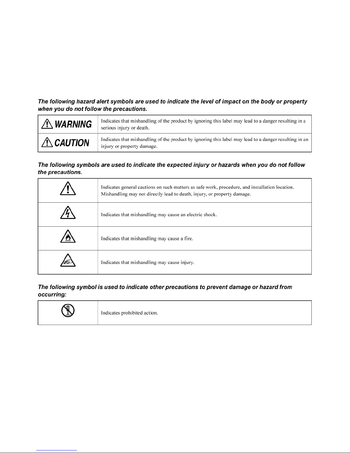
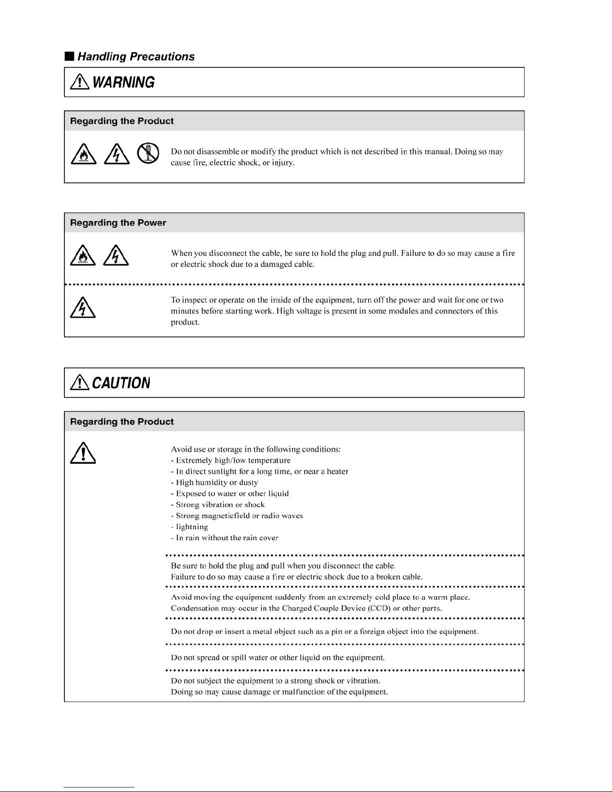
This manual describes the precautions using various pictorial symbols for you to use
the product safely. Please read these precautions thoroughly before use. The symbols
and meanings are as follows:
SAFETY PRECAUTIONS
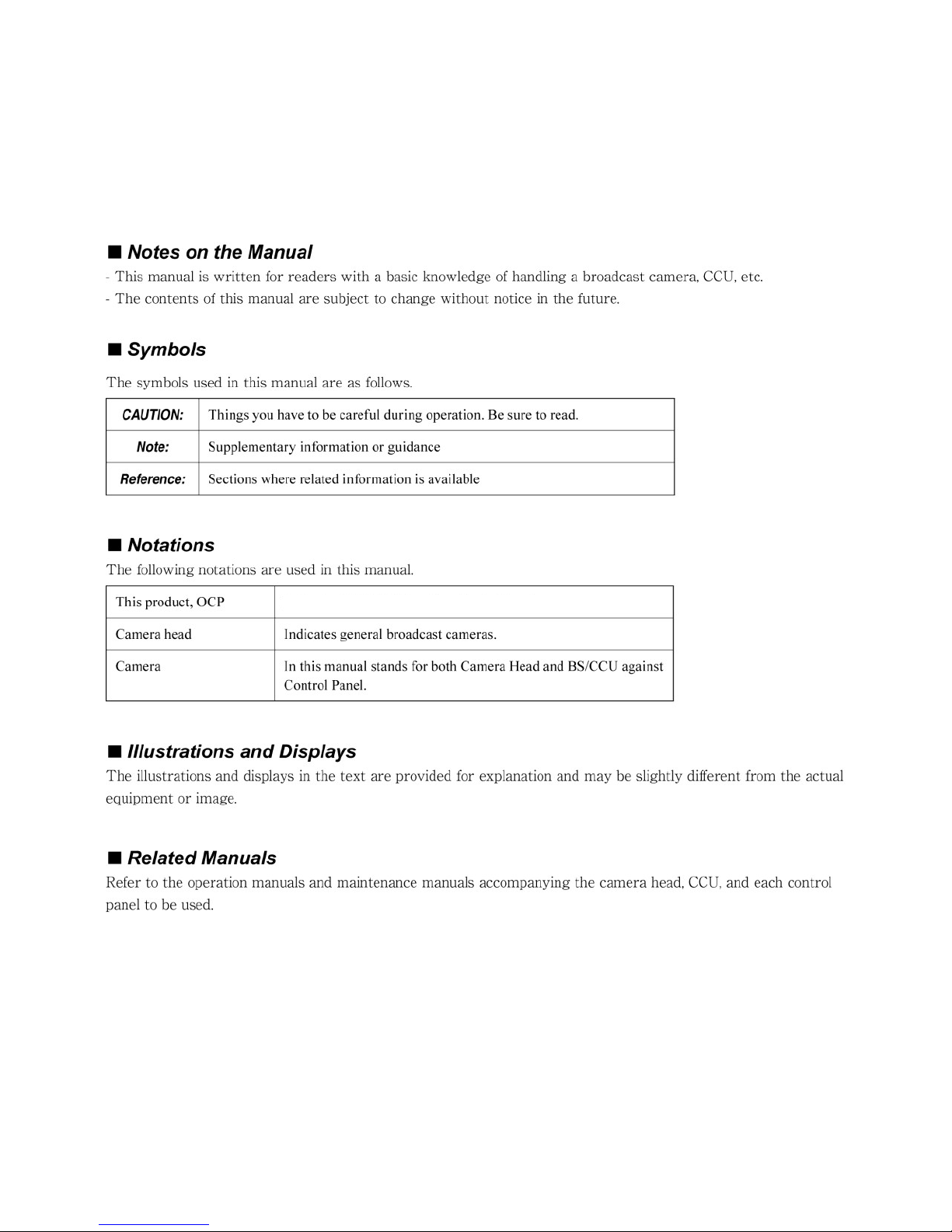
HOW TO READ THE OPERATION MANUAL
HOW TO READ THE OPERATION MANUAL
This page explains general notes on reading the OCP-10 Operation Manual, and the
symbols and notations used in the manual.
Indicates OCP-10 Operation Control Panel.


OCP-10
Operation Control Panel
OPERATION MANUAL
CONTENTS
1. Outline .................................................................................. 1
1.1 Outline .................................................................................................. 1
1.2 Features................................................................................................ 1
1.3 External View ....................................................................................... 2
2. Name and Function of Each Part ........................................ 5
2.1 OPT Indicator ....................................................................................... 7
2.2 GAIN Controls ...................................................................................... 7
2.3 F. VR Controls ...................................................................................... 7
2.4 ENABLE Switch ................................................................................... 8
2.5 AWB Switch.......................................................................................... 8
2.6 ABB Switch .......................................................................................... 8
2.7 SCENE File Switch .............................................................................. 8
2.8 F.VR Function Selector Switch .......................................................... 9
2.9 EXT Indicator ....................................................................................... 9
2.10 F1 & F2 Switches ............................................................................... 9
2.11 Character Indicator ........................................................................... 9
2.12 Rotary Switch .................................................................................... 9
2.13 Camera Number Indicator ................................................................ 9
2.14 MASTER PED Indicator ................................................................... 10
2.15 MASTER PED Control ..................................................................... 10
2.16 IRIS RANGE/SENS Control ............................................................. 10

2.17 RELATIVE Switch ............................................................................ 10
2.18 FULL Switch ..................................................................................... 10
2.19 AUTO Switch .................................................................................... 10
2.20 IRIS Indicator ................................................................................... 10
2.21 IRIS Control ...................................................................................... 11
2.22 PREVIEW Switch ............................................................................. 11
2.23 KNOB FREE Switch ......................................................................... 11
2.24 CALL Switch .................................................................................... 11
2.25 HEAD PWR Indicator ....................................................................... 11
2.26 ALARM Indicator ............................................................................. 11
2.27 COMMAND Connector .................................................................... 12
2.28 EXT (PREVIEW) Connector ............................................................ 12
2.29 Connector for LAN (Option) ........................................................... 12
2.30 ICCP/Ether Selector Switch (Option) ............................................. 12
3. F.VR Controls ..................................................................... 13
3.1 F.VR Function Selection ................................................................... 13
3.2 F.VR Control Page Setting ................................................................ 14
3.3 List of Pages for F.VR1 and F.VR2 ................................................... 15
4. F. Switch ............................................................................. 16
4.1 F. Switch Customize Function .......................................................... 16
4.2 List of Switch Functions ................................................................... 17
4.2.1 VR Clear Operation ..................................................................... 18
4.2.2 Menu Operation from OCP ........................................................ 19
5. Rotary Switch ..................................................................... 20
5.1 Selection and Setting of Rotary Switch Functions ........................ 20
5.2 List of Rotary Switch Functions ...................................................... 21
5.3 SCENE FILE Setting Method ............................................................ 22

6. Ethernet (Option) ............................................................... 23
6.1 Conceptual Diagram of Network ...................................................... 23
6.2 Ethernet connection method ........................................................... 24
7. Panel Configuration ........................................................... 25
7.1 Panel Configuration Menu ................................................................ 25
7.2 List of Panel Configuration Settings ............................................... 27
7.3 List of Tally Guard Functions ........................................................... 28
7.4 IRIS Position Adjustment Function ................................................. 29
7.5 Program Number Indication ............................................................. 30
7.6 Limit Functions (Control Depth) ...................................................... 31
7.6.1 List of Limited Functions for F. Switch Selection ................... 31
7.6.2 List of Limited Functions for Rotary Switch ............................ 32
7.7 Setting IP Address/Subnet Mask/Default Gateway ........................ 33
8. Troubleshooting ................................................................. 35
8.1 Blinking ALARM Indicator ................................................................ 35
8.2 Adjustment of IRIS Friction .............................................................. 35
8.3 Initialization ........................................................................................ 36
9. Specification ...................................................................... 37
9.1 Rating ................................................................................................. 37
9.2 Pin Function of External Connector ................................................ 38
9.2.1 COMMAND Connector ............................................................... 38
9.2.2 EXT Connector ............................................................................ 39
10. Changing Information ...................................................... 43


1
1. Outline
1.1 Outline
The OCP-10 is an operation control panel that is used by connection to a BS
(Base Station) or CCU (Camera Control Unit) or Camera Head.
1.2 Features
Knob Free function is adopted
The OCP-10 adopts the knob free function which combines the advantages of absolute
control of potentiometers with the advantages of relative control of rotary encoders.
By pressing and holding the Knob Free switch, the potentiometers (excluding iris
control) are electronically disconnected from controlling the camera. So they can be
re-indexed to mid-range for reference or turned to the opposite end when the mechanical
range of the control hits the end, but the function itself has more control range.
F.VR Control
One-touch operation is available for allocation of various functions to two user function
F.VR (variable resistor) controls. In addition, the user can customize which pages of
functions that the OCP has access to.
F. Switch
Two F. switches (F1/F2) are provided, so the user can set the functions freely.
Assigning functions necessary for each user is available, and so the operational
flexibility expands.
Note : Switches of the OCP and control functions become inoperable if the
connecting camera does not have the corresponding functions.
Reference : Refer to the instruction manual of the camera for functions that can
be operated.
Ethernet compatible (option)
In addition to control by the conventional serial command, control by an Ethernet
network connection is also available. The Operation by LAN cable connection is
available. In addition, because the OCP-10 corresponds to PoE+ (Power over
Ethernet), supplying power by the LAN cable is available.
2
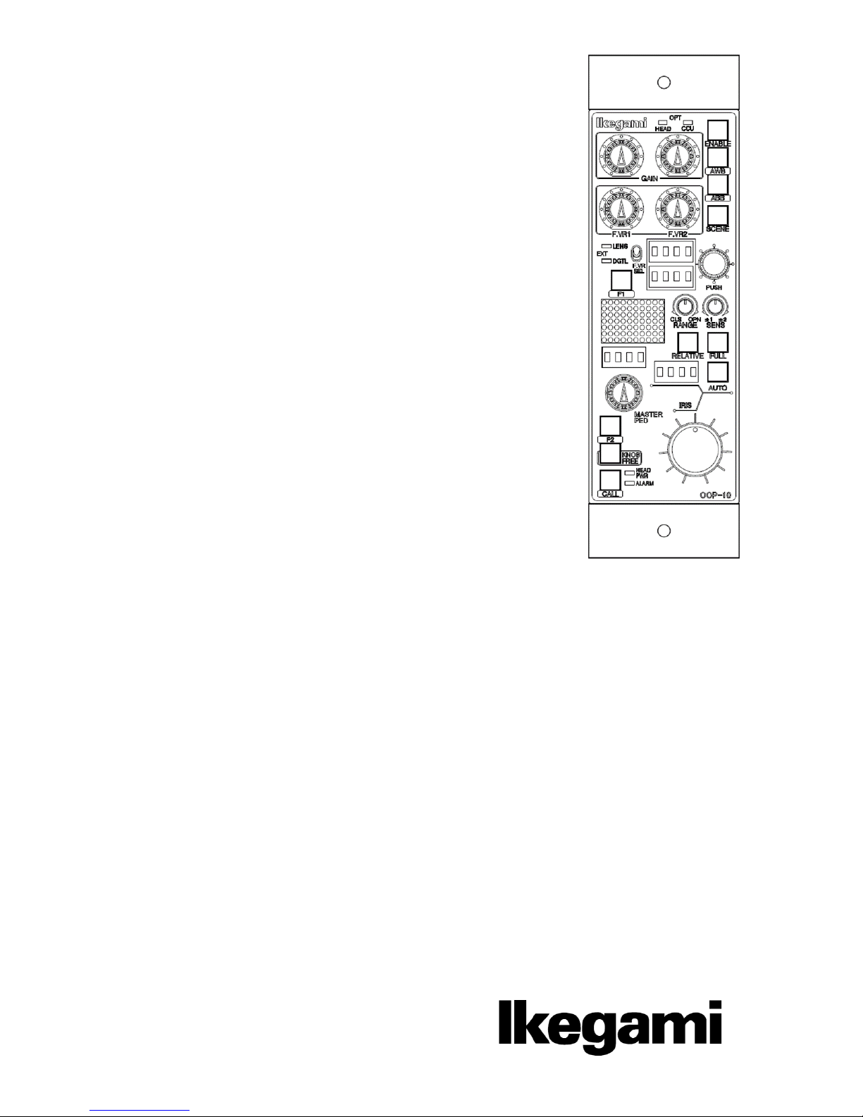
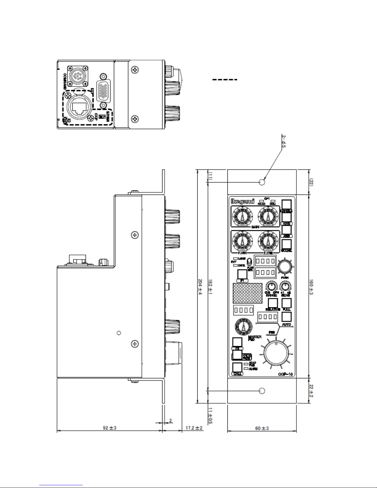
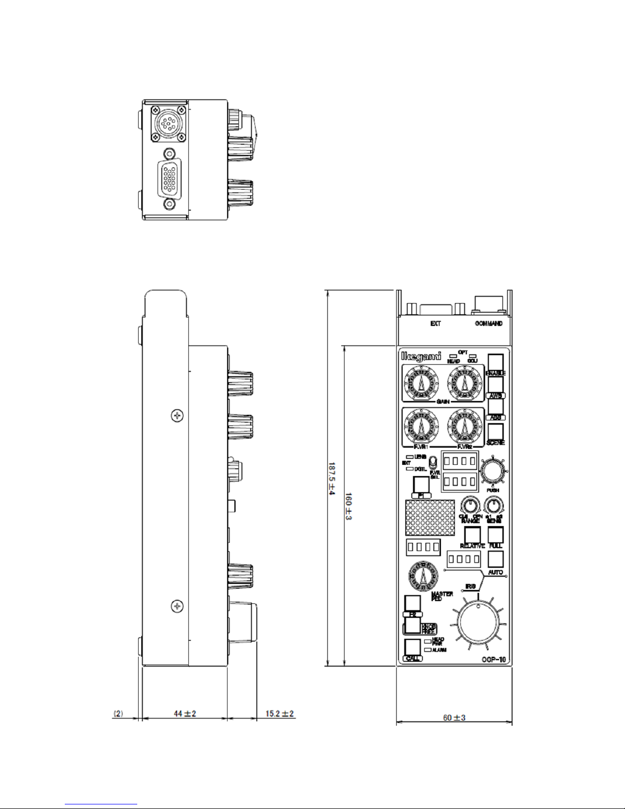
1.3 External View
1) VR TYPE
Option
3
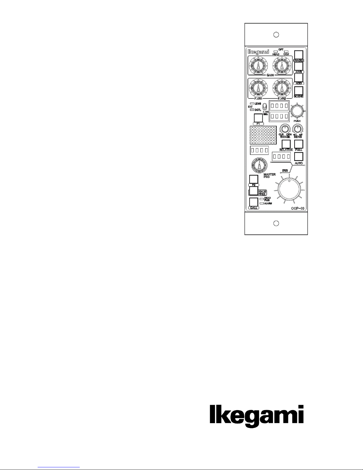
2) Slim TYPE
 Loading...