

Ikegami HDK-55, FA-55 Operation Manual

HDK-55
(
FA-55
HIGH DEFINITION CAMERA SYSTEM
OPERATION MANUAL
)


OUTLINE
1
HDK-55
(
FA-55
HIGH DEFINITION CAMERA SYSTEM
OPERATION MANUAL
)
NAME and FUNCTION
INSTALLATION and
CONNECTION
OPERATION
CAMERA SETTINGS and
ADJUSTMENT
TROUBLE SHOOTING and
MAINTENANCE
SPECIFICATIONS
2
3
4
5
6
7
1206 Edition (U)
CHANGING INFORMATION
Copyright © 2012 Ikegami Tsushinki Co., Ltd.
We reserve the copyright on the software we create.
No part of this publication may be modified or reproduced in any form, or by any means, without prior written per mission from
Ikegami Tsushinki Co., Ltd.

PRODUCTS CONFORMING TO RoHS DIRECTIVE
PRODUCTS CONFORMING TO RoHS DIRECTIVE
Following products described in this manual are products conforming to RoHS directive.
· HDK-55 Color Camera
· VF421HD, VF13XHD, VFL912HD, VFL200HD Viewfinder
· BSF-55 Base Station
· OCP-200 Operation Control Panel
· MCP-200 Maintenance Control Panel
· CPH-200 Control Panel Hub
· BSH-200 Base Station Hub
Products conforming to RoHS directive include products that do not contain specified hazardous substances such as lead, mercury,
cadmium, hexavalent chromium, polybrominated biphenyl (PBB) and polybrominated diphenyl ether (PBDE) in electrical and
electronic equipment excluding following exemption applications based on the EU directive (Directive2002/95/EC).
* About RoHS Directive
The RoHS directive stands for "the Restriction of the Use of Certain Hazardous Substances in Electrical and Electronic Equipment"
and is one of environmental directives in Europe. This directive restricts the use of specified hazardous substances in electrical and
electronic equipment.
Applications exempted from RoHS directive compliance
●
Followings applications are permitted as exemptions from RoHS directive compliance.
1. Mercury in compact fluorescent lamps not exceeding 5mg per lamp
2. Mercury in straight fluorescent lamps for general purposes not exceeding:
· halophosphate 10mg
· triphosphate with a normal lifetime 5mg
· triphosphate with a long lifetime 8mg
3. Mercury in straight fluorescent lamps for special purposes
4. Mercury in other lamps not specifically mentioned in this Annex
5. Lead in the glass of cathode ray tubes, electronic components and fluorescent tubes
6. Lead as an alloying element in steel containing up to 0.35% lead by weight, aluminum containing up to 0.4% lead by weight
and as a copper alloy containing up to 4% lead by weight
7. Lead in following items
· Lead in high melting temperature type solders (i.e. tin-lead solder alloys containing more than 85% lead)
· Lead in solders for servers, storage and storage array systems
· Lead in solders for network infrastructure equipment for switching, signaling, transmission as well as network
management for telecom munication
· Lead in electronic ceramic parts (e.g. piezoelectronic devices)
8. Cadmium plating except for applications banned under Directive 91/338/EEC amending Directive 76/769/EEC relating to
restrictions on the marketing and use of certain dangerous substances and preparations
9. Hexavalent chromium as an anti-corrosion of the carbon steel cooling system in absorption refrigerators
10. Lead used in compliant pin connector systems
11. Lead as a coating material for the thermal conduction module C-ring
12. Lead and cadmium in optical and filter glass
13. Lead in solders consisting of more than two elements for the connection between the pins and the package of microprocessors
with a lead content of more than 80% and less than 85% by weight
14. Lead in solders to complete a viable electrical connection between semiconductor die and carrier within integrated circuit Flip
Chip packages
15. Decabrominated diphenyl ether (Deca-BDE) in polymeric applications
HDK-55 1206 VER1 (U)
i
MAINTENANCE OF PRODUCTS CONFORMING TO RoHS DIRECTIVE
MAINTENANCE OF PRODUCTS CONFORMING TO RoHS DIRECTIVE
Work with care about followings for maintenance of products conforming to RoHS directive.
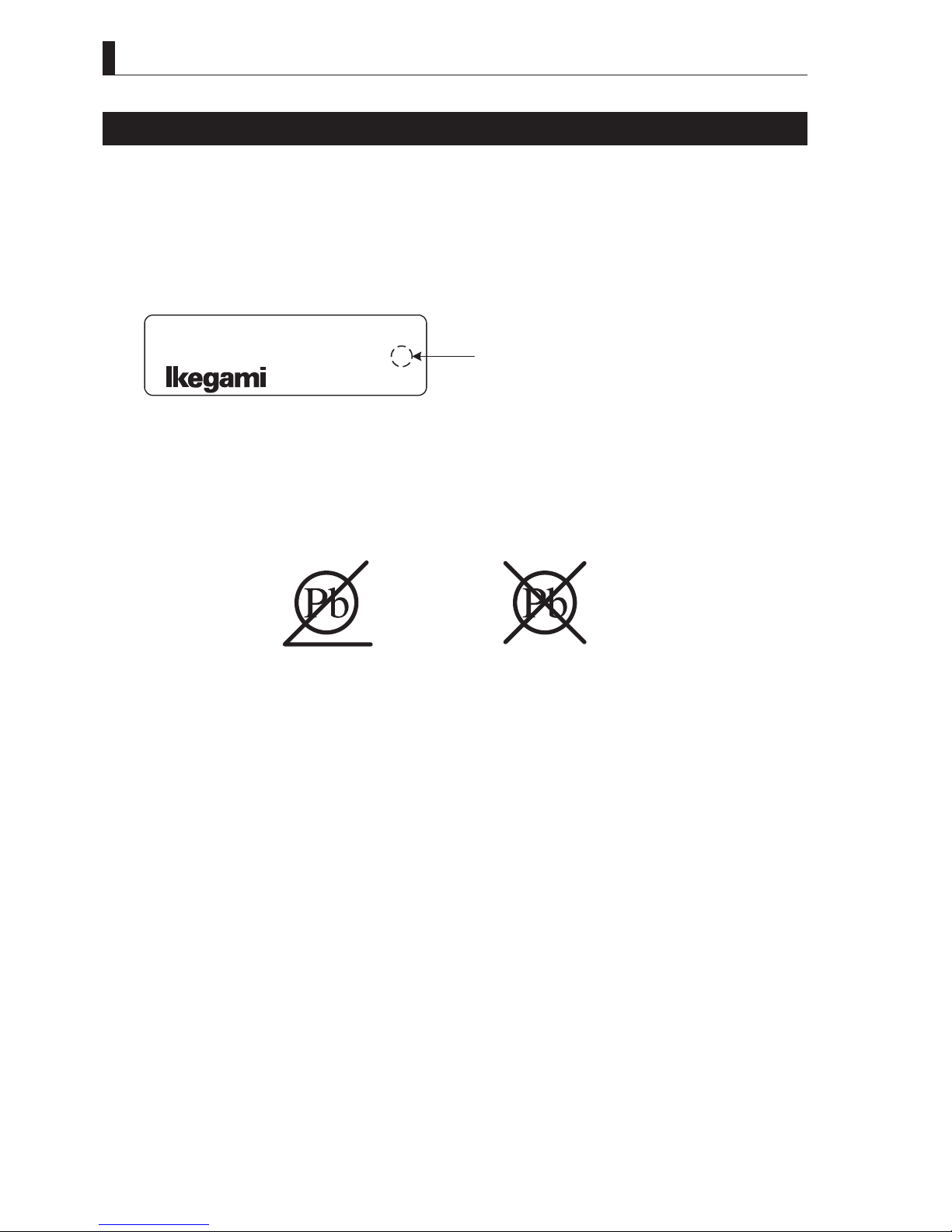
1. Identification
· For products conforming to RoHS directive, the letter "E" is appended at the end of the serial number on the label. For models
that the letter cannot be appended to the serial number, the letter "E" will be described in a distinguishable position on the
label. A description example on a main label is shown below.
MODEL HDK-55
SERIALNo. AA123456 E
Label
· Print-circuit board of the products conforming to RoHS directive is manufactured by following methods.
[1] Blue resist ink is used for the print-circuit board. (The color of conventional print-circuit board is green.)
[2] Either one of the following marks is indicated by a serigraph or label.
Product conforming to RoHS directive
Phase 3A Phase 3
2. Soldering
Since the melting point of lead-free solder used for the products conforming to RoHS directive is 20 to 45 degrees Celsius higher
than that of conventional solder with lead (Sn-Pb eutectic solder), a high temperature needs to be set to a soldering iron. Taking
allowable temperature limit of the parts and stable work into consideration, use a soldering iron with excellent thermal recovery
characteristics.
· Recommended solder composition is "Sn/3.0Ag/0.5Cu" or equivalent.
· Separate the soldering iron exclusively for RoHS products and the soldering iron for conventional use.
· Set the temperature of the soldering bit to 350 to 370 degrees Celsius.
The temperature may need to be adjusted according to the size of the copper foil land on the print-circuit board and the tip
width of the soldering bit.
· Finish by a lead-free solder looks dull or whitish compared to conventional solder with lead.
· If the customer mixed the lead-solder with the main body wiring or the circuit board, it becomes guarantee off the subject.
Ikegami doesn't guarantee to do the repair work. Because the solder polluted with lead cannot be removed.
3. Parts
Be sure to use parts conforming to RoHS directive.
ii
HDK-55 1206VER1 (U)

INFORMATION TO THE USER
INFORMATION TO THE USER
1. This equipment has been tested and found to comply with the limits for a Class A digital device, pursuant to Part 15 of the FCC
Rules. These limits are designed to provide reasonable protection against harmful interference when the equipment is operated
in a commercial environment. This equipment generates, uses, and can radiate radio frequency energy and, if not installed and
used in accordance with the instr uction manual, may cause har mful interference to radio communications.
Operation of this equipment in a residential area is likely to cause harmful interference in which case the user will be required
to correct the interference at his own expense.
Changes or modifications not expressly approved by the party responsible for compliance could void the user's authority to
operate the equipment.
2. Declaration of conformity
The CE mark means that the following products will meet the Directive 2004/108/EC,2006/95/EC and the Standards EN55103-
1 E4-E5, EN55103-2 E4-E5 (for EMC), EN60950-1 (for LVD).
For European customer.
3. Rated current value of the camera when BSF-55 are used for the system operation is shown below.
Rated current value
· BSF-55 DC180V : 0.8A
HDK-55 1206 VER1 (U)
iii
SAFETY PRECAUTIONS
N
SAFETY PRECAUTIONS
This manual describes the precautions using various pictorial symbols for you to use the product safely. Please read these
precautions thoroughly before use. The symbols and meanings are as follows:
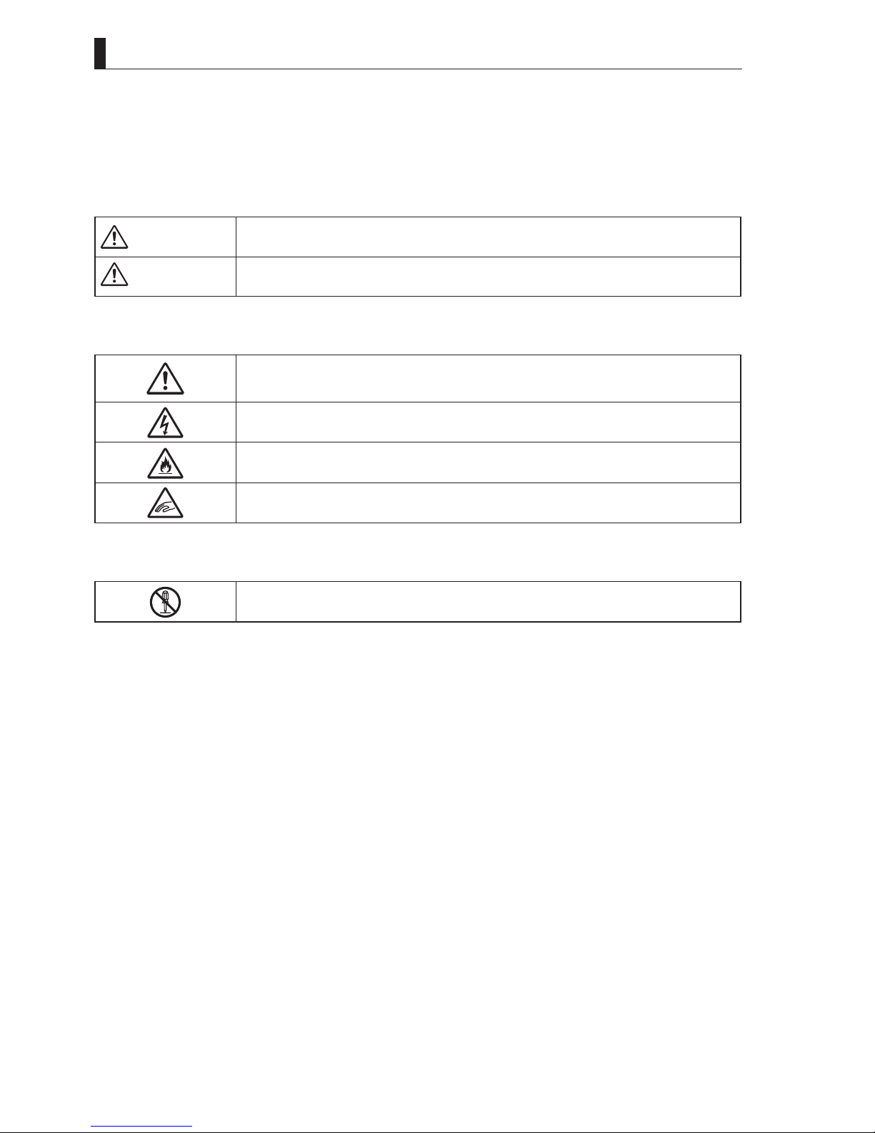
The following hazard alert symbols are used to indicate the level of impact on the body or property
when you do not follow the precautions.
WARNING
CAUTIO
The following symbols are used to indicate the expected injury or hazards when you do not follow
the precautions.
The following symbol is used to indicate other precautions to prevent damage or hazard from
occurring:
Indicates that mishandling of the product by ignoring this label may lead to a danger resulting in a
serious injury or death.
Indicates that mishandling of the product by ignoring this label may lead to a danger resulting in an
injury or property damage.
Indicates general cautions on such matters as safe work, procedure, and installation location.
Mishandling may not directly lead to death, injury, or property damage.
Indicates that mishandling may cause an electric shock.
Indicates that mishandling may cause a fire.
Indicates that mishandling may cause injury.
Indicates prohibited action.
iv
HDK-55 1206 VER1 (U)
䂓
N
Handling Precautions
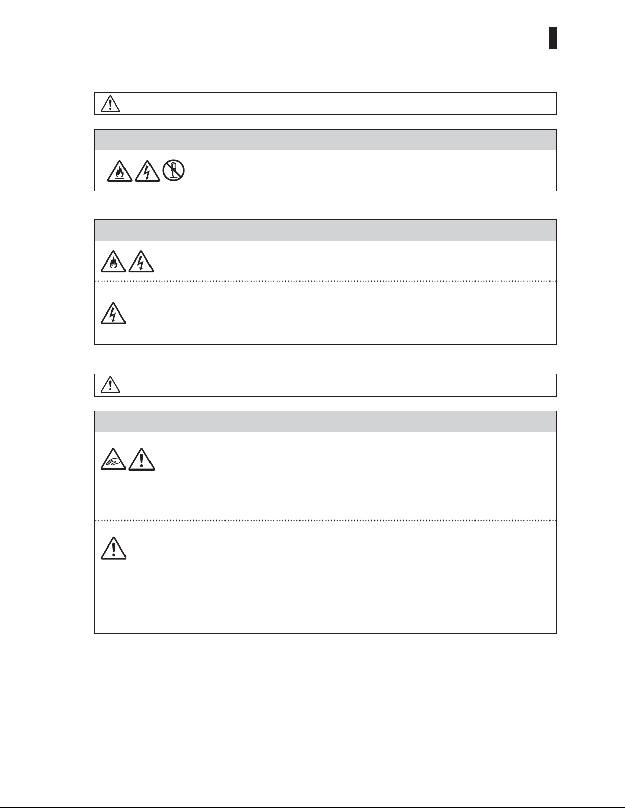
WARNING
Regarding the Product
SAFETY PRECAUTIONS
Regarding the Power
CAUTIO
Regarding the Product
Do not disassemble or modify the product which is not described in this manual. Doing so may
cause fire, electric shock, or injury.
When you disconnect the cable, be sure to hold the plug and pull. Failure to do so may cause a fire
or electric shock due to a damaged cable.
To inspect or operate on the inside of the equipment, tur n off the power and wait for one or two
minutes before starting work. High voltage is present in some modules and connectors of this
product.
When you want to intercept a power supply surely, I pull a fiber cable of the camera side, or, please
pull an AC plug of the BS/CCU side.
Do not lift or hold the camera by the projection parts.
If you lift or hold the camera by the viewfinder or the lens, you are prone to dropping it. Moreover,
the connection parts between the camera and the viewfinder, or the camera and the lens may be
exposed to unnecessary pressure, which may cause equipment damage.
Always install the accessories or connect the cables after placing the camera on a fixed position.
When installing such accessories as lens or microphone, fix the camera on a stable place (e.g. on a
table, a tripod, etc.).
Avoid use or storage in the following conditions:
- Extremely high/low temperature
- In direct sunlight for a long time, or near a heater
- High humidity or dusty
- Exposed to water or other liquid
- Strong vibration or shock
- Strong magnetic field or radio waves
- lightning
- In rain without the rain cover
HDK-55 1206 VER1 (U)
v
SAFETY PRECAUTIONS
Regarding the Product
Be sure to hold the plug and pull when you disconnect the cable.
Failure to do so may cause a fire or electric shock due to a broken cable.
Avoid moving the equipment suddenly from an extremely cold place to a warm place.
Condensation may occur in the Charged Couple Device (CCD) or other parts.
Do not drop or insert a metal object such as a pin or a foreign object into the equipment.
Do not spread or spill water or other liquid on the equipment.
Do not subject the equipment to a strong shock or vibration.
Doing so may cause damage or malfunction of the equipment.
Since a CCD is adopted as the image sensor in picture elements, no burning occurs in ordinary
operation. However, when shooting a subject which emits an excessive amount of light (such as the
sun) for long hours, take great care for temperature increase inside of the CCD.
Laser beams may damage the CCDs. If you shoot a scene that includes a laser beam, be careful not
to let a laser beam become directed into the lens of the camera.
Before connecting a VTR or accessories, make sure that the camera and equipment to be connected
are powered off. Also, be sure to use dedicated cables.
Excessive sound pressure from the headset may cause a hearing loss.
Regarding the Power and the Lithium Battery
Use the product in compliance with the rating of the fuse within the product and that within the
Camera Control Unit (BS). Otherwise, a fault can occur.
Do not use an unspecified battery.
Wrong usage of batteries may cause liquid leak, explosion, and heat, and at worst injur y or fire.
When changing or discarding a battery, please contact Ikegami's sales and service centers.
Risk of explosion if battery is replaced by an incorrect type. Dispose of used batteries according to
the instructions.
Regarding the Fiber Connector and the Fiber Optic Cable
Fiber optic cable connectors are quite similar to each other in shape. Before connecting fiber optic
cables, thoroughly check male or female, the diameter, type and manufacturer of connectors.
If the ferrule is dirty, wipe the dirt off with cotton swabs soaked in alcohol.
The fiber optic cable supplies DC180V power from the BS to the camera.
Although safety measures are fully taken such as the safety circuit that stops the power supply
from the BS within a short time after an optical fiber cable is removed or short-circuited, never
force to bend, twist, or damage the cable, and take great care when handling.
vi
HDK-55 1206 VER1 (U)
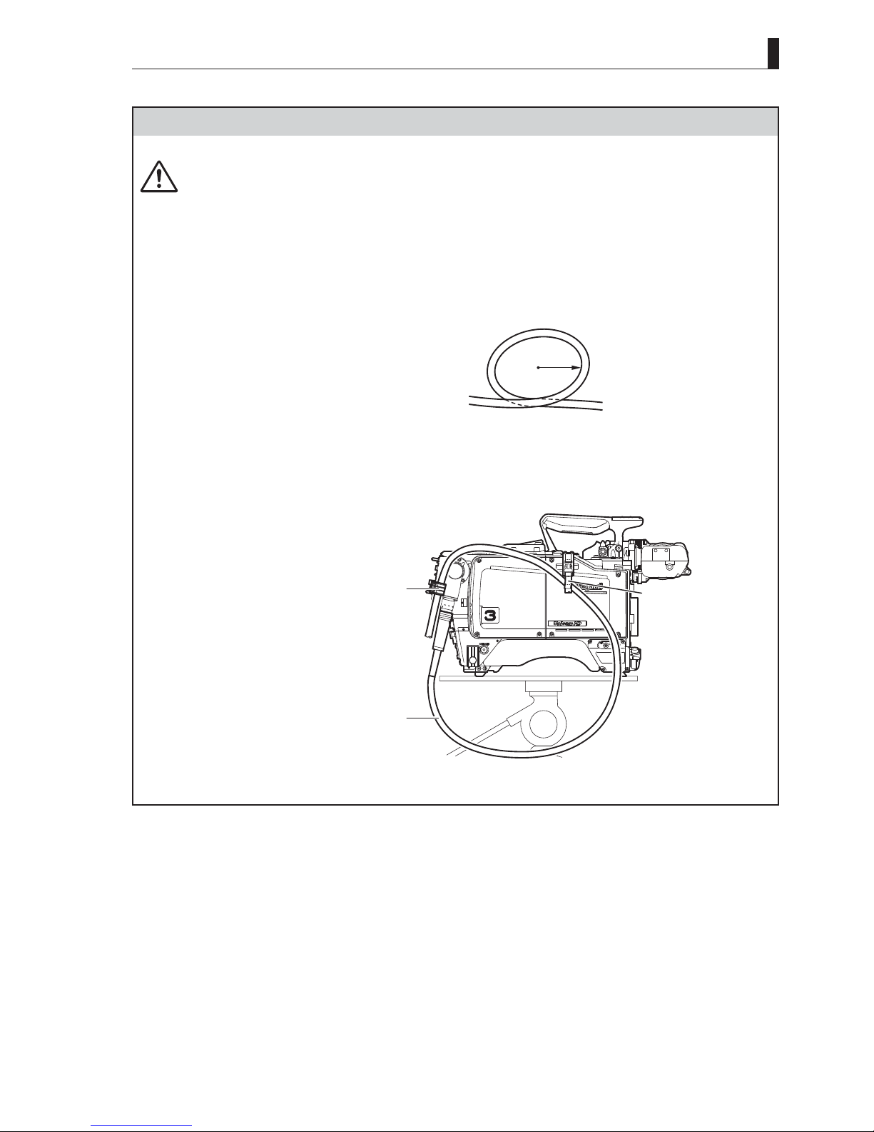
Regarding the Fiber Connector and the Fiber Optic Cable
Take care for the following:
- When disconnecting the fiber optic cable from the camera or from the BS, always hold the fiber
connector (plug) and not the cable.
- Do not crush the cable.
- Since there can be various obstacles (such as a corner of a building, glass, rough ground surface)
in places where the cable is connected, do not drag the cable without winding.
- Turn off the power before removing the fiber optic cable.
- The allowable radius of curvature of fiber optic cables is approximately six times of the outer
diameter of cables (approx. 60 mm for a φ9.2mm-wide cable). Do not force to wind less than
specified. Forcible winding can break fiber leads within the cable.
- When connecting a fiber optic cable to a fiber connector, anchor the fiber optic cable with a cable
clamp.
Radius
Approx. 60mm
Fiber Optic Cable
SAFETY PRECAUTIONS
CAMERA CABLE Clamp
Optical Fiber Cable
CAMERA CABLE Clamp
(optional)
HDK-55 1206 VER1 (U)
vii
SAFETY PRECAUTIONS
䂓
Environmental Cautions
Regarding the product
When continuously operating the product in a rainy, cold or hot conditions, use a rain cover, coldweather cover, and shade cover respectively.
Avoid storing the product in a dusty place for a long time. If unavoidable, use a dustproof cover.
When shooting in places such as airports, militar y bases or transmitting stations where magnetic
and radio fields are excessively strong, completely shield the camera by covering it with aluminum
foil.
䂓
Maintenance
Regarding the product
Before performing maintenance on the product, be sure to turn off the power for safety and for
protection against malfunction.
Clean the product using a dry and soft cloth.
If the stain is hard, soak the cloth with water or detergent, wring well and wipe. If you use
detergent, wipe off the detergent with a cloth that is soaked in just water and wrung well.
䂓
Notice for Use
- When car rying or storing the product, always use a carrying case.
- Before shooting important subjects, take test shots to obtain the desired effect.
- After using the product, always turn off the power.
䂓
Regular Maintenance Recommended
This product includes parts that wear out and have a limited life even in proper use or storage. Therefore, regular maintenance is
recommended to extend the life and safe use of this product for a long time. Please contact Ikegami's sales and service centers for
the regular maintenance and repair of our products.
viii
HDK-55 1206 VER1 (U)
HOW TO READ THE OPERATION MANUAL
HOW TO READ THE OPERATION MANUAL
This page explains general notes on reading the HDK-55 Operation Manual, and the symbols and notations used in the manual.
䂓
Notes on the Manual
- This manual is written for readers with a basic knowledge of handling broadcast cameras.
- The contents of this manual are subject to change without notice in the future.
䂓
Symbols
The symbols used in this manual are as follows:
CAUTION:
Things you have to be careful during operation. Be sure to read.
Note:
Reference:
Ter m :
䂓
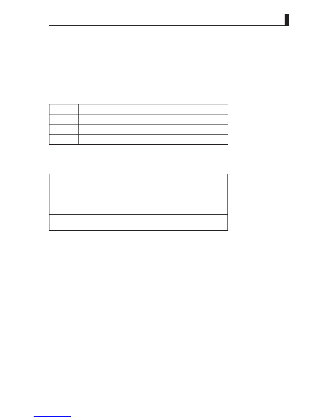
Notations
The following notations are used in this manual.
This product, camera Indicates HDK-55. (Including FA-55)
BS Indicate BSF-55 Base Station.
OCP Basically indicates OCP-200 Operation Control Panel.
MCP Basically indicates MCP-200 Maintenance Control Panel.
" " - " " - " " Indicates the items enclosed by double quotes (") are to be
䂓
Illustrations and Displays
The illustrations and displays in the text are provided for explanation and may be slightly different from the actual equipment or
image.
Supplementary information or guidance
Sections where related information is available
Explains the meaning of a term you need to know.
selected and confi rmed in the order shown.
䂓
Related Manuals
- BSF-55 Base Station Operation Manual
- OCP-200 Operation Control Panel Operation Manual
- MCP-200 Maintenance Control Panel Operation Manual
- CPH-200 Control Panel HUB / BSH-200 Base Station Hub Setup Manual
HDK-55 1206 VER1 (U)
ix

HOW TO READ THE OPERATION MANUAL
Structure of Operation Manual
䂓
HDK-55 High Definition Camera System Operation Manual is intended to both safely and smoothly operate the HDK-55.
The Operation Manual consists of seven chapters. By reading it in sequence, you can smoothly perform a series of steps, from
connection to operation. Furthermore, by combination use of BSF-55 (base station), this product enables not only stand-alone
VTR location shooting but also various shooting styles such as studio shooting and field shooting as a system camera. Refer to
other manuals such as for the BSF-55.
Chapter 1
Chapter 2
Chapter 3
Chapter 4
Chapter 5
OUTLINE
Explains the features and the main operating systems of this product.
If you are not familiar with HDK-55 High Definition Camera System, please start with this chapter.
NAME and FUNCTION
Explains the name and function of each part of the Camera.
INSTALLATION and CONNECTION
Explains how to mount this product, lens, and viewfinder.
Taking examples of studio shooting, stand-alone shooting, and VTR location shooting, explains how
to connect this product to the peripheral equipment.
OPERATION
Explains setup before shooting.
Before shooting for the first time, read this chapter and check that this product is operating nor mally.
CAMERA SETTINGS and ADJUSTMENT
This product realizes detailed settings to support a wide range of operations and various video
expressions through the menu window. This chapter explains switch settings, menu settings, and DIP
switch settings on the modules inside of the Camera.
Chapter 6
Chapter 7
TROUBLE SHOOTING and MAINTENANCE
When the alarm lamp lights during the operation of this product, read here to know the problem. This
chapter also explains the regular maintenance such as cleaning of connectors and resetting of breaker.
SPECIFICATIONS
Explains the specifications of this product.
CHANGING INFORMATION
Contains revision information of design revision or customer-specific specification requested
by customers. Read by comparing with the main text of the operation manual. ("CHANGING
INFORMATION" may be sent to you later on.)
x
HDK-55 1206 VER1 (U)

HDK-55
CONTENTS
(
FA-55
High Definition Camera System
Operation Manual
PRODUCTS CONFORMING TO RoHS DIRECTIVE. . . i
MAINTENANCE OF PRODUCTS CONFORMING
TO RoHS DIRECTIVE ........................ii
INFORMATION TO THE USER .................. iii
SAFETY PRECAUTIONS .......................iv
HOW TO READ THE OPERATION MANUAL ....... ix
Chapter 1 OUTLINE
1.1 Features of This Product ................. 3
1.2 Operating Systems ...................... 5
1.3 Connection Diagram. . . . . . . . . . . . . . . . . . . . . 9
Chapter 2 NAME and FUNCTION
2.1 Camera and Viewfinder ................. 13
Camera Right View .................... 13
Camera Left View ...................... 17
Camera Front View ..................... 19
Camera Rear View ..................... 21
Viewfinder (VF421HD) .................. 25
2.2 Displays in the Viewfinder ............... 27
LED Indicator ......................... 27
Center Marker, Safety Marker, Frame Marker
Zebra Indicator ........................ 27
Side Mask Function .................... 28
Display Mode ......................... 28
Viewfinder Display ..................... 28
Chapter 3
INSTALLATION and CONNECTION
3.1 Preparation ...........................33
Product Use Environment ............... 33
Make sure the Power Switch is OFF ....... 33
Connection Example for Each Operating
System .............................. 33
3.2 Camera and Peripheral Installation and
Connection ........................... 39
Mounting/Removing the Camera on/from the
Tripod ............................... 39
Mounting and Removing the Lens ......... 41
Mounting and Removing the Viewfinder .... 43
Attaching the Microphone ............... 45
Connecting the Headset ................. 46
Attaching the Shoulder Belt .............. 46
.. 27
)
3.3 Power Connection ..................... 47
Power Supply from POWER .............. 47
Power Supply from BS .................. 48
3.4 Monitor Connection .................... 51
Connecting Camera and Monitor .......... 51
3.5 BS Connection ........................ 52
Connecting Camera and BS ............. 52
Chapter 4 OPERATION
4.1 Operating Procedures .................. 57
4.2 Switch Position Check .................. 58
4.3 Turning ON Power ..................... 60
Power Supply from POWER .............. 60
Power Supply from BS .................. 60
4.4 Viewfinder Adjustment .................. 62
Diopter Adjustment and Screen Adjustment . . 62
Display Mode Check ................... 62
4.5 Output Signal Check ................... 63
Color-Bar Signal Check ................. 63
Test Pulse (CAL Signal) Check ........... 64
External Chart Check ................... 64
4.6 Auto Setup ........................... 65
Auto White Balance .................... 66
Auto Black Balance .................... 67
Auto Black Shading ....................68
4.7 Preparation for Shooting in Particular
Environment .......................... 69
Chapter 5
CAMERA SETTINGS and ADJUSTMENT
5.1 Settings Using Switches on the Camera .... 73
Adjusting Headset Volume ............... 73
Selecting Shutter Speed .................74
Enhancing the Vertical Resolution
(Super-V Function) ..................... 76
Switching the GAIN .................... 77
Allocating Functions to the P.FUNC Switch . . 78
Screen Detail Enhancement (DTL) ........ 79
5.2 Settings from the Menu ................. 80
Basic Operation of the Menu ............. 80
Menu Configuration and content .......... 83
5.3 Using the Memory Card ................. 95
HDK-55 1206 VER1 (U)
xi

CONTENTS
Chapter 6
TROUBLE SHOOTING and MAINTENANCE
6.1 Alarm Lamp on the OCP or MCP
Flashes ON and OFF .................. 101
6.2 "TEMP!!" or "FAN!!" Appears
on the VF Screen ..................... 102
6.3 Initializing the Settings of this Product ..... 103
6.4 Cleaning Camera Connectors ........... 105
6.5 Reset the Breaker ..................... 109
Chapter 7 SPECIFICATIONS
7.1 HDK-55 Specifications ..................113
7.2 External Dimensions Diagram ............115
7.3 External Connections ...................119
7.4 Scene File ........................... 132
CHANGING INFORMATION ................... 133
xii
HDK-55 1206 VER1 (U)

OUTLINE
1

2
HDK-55 1206 VER1 (U)

HDK-55
■
This product realizes high quality pictures and advanced functions using the intelligent
digital technique nurtured in the HDK series. Furthermore, we succeeded to create a
small, light-weighted camera system whose weight and balance has been sought for the
improvement of the portable camera operation.
- A 16-bit (65,535 gradation) A/D converter produces pictures with a broader range of
gradation from darker par ts to highlighted parts.
1.1 Features of This Product
1.1 Features of This Product
Fusion of High Quality CCD and Superb Image Processing Techniques
■
2.3 Million pixel new interlace 3CCD
A 2.3-million pixel 2/3-inch AIT type 1080i CCD is employed to achieve superb picture
quality with a horizontal resolution of 1,000 TV lines and an S/ N ratio of more then 60dB.
■
Newly developed digital process IC
16-bit A/D conversion and new digital processing (computation) within the camera digitizes
not only video signals but also nonlinear image processing used for the white shading
correction and Gamma correction. This always achieves high quality pictures, advanced
functions, and high reliability with stability.
Support of Various Picture Expressions
■
DTL Correction
Includes a horizontal and vertical DTL correction circuit in which red, green and blue video
are independently digitally processed.
You can obtain the full resolution HDTV picture quality with little noise even in the standalone VTR shooting.
11
OUTLINE
■
Wideband Digital DTL
Includes an advanced digital DTL circuit to improve reproduction, including texture
and sheen. Furthermore, improves richer reproduction of details with little noise in dark
background and details in skin tone.
■
Focus Assist Function
A focus assist area is provided in the VF image to aid the cameraman in finding the focus.
The focus assist area can only be displayed during focusing when operation of the lens
focus ring or operation of the focus switch, etc. act as a trigger.
■
Six-axis + Two-axis Color Corrector
Includes a color corrector f unction that enables you to adjust hue and saturation of six
primary colors (R, G, B, cyan, yellow, magenta).
Also, includes a color corrector function to adjust two selected colors.
■
Super KNEE
Includes a super KNEE function which produces the KNEE process with less saturation
loss, and without changing the hue of the highlighted parts. Produces a more natural
highlight appearance, rather than washing out the color.
HDK-55 1206 VER1 (U)
3

1.1 Features of This Product
Pursuit for Superb Operation and Ease of Use
■
Application of Conventional Standard 2/3-inch Lenses
As the lens mount, BTA S-1005B is used. You can use not only HD lenses but also SD
camera lenses for SDTV portable cameras as they are.
■
High Performance Viewfinders
Employs a magnifying eye-piece in the 2-inch B/W viewfinder to improve the visibility
of fine picture detail. It is also possible to choose a 2-inch color viewfi nder, 5-inch high
precision B/W viewfinder or a 9-inch liquid cr ystal color viewfinder.
■
Low Center of Gravity, Light Weight, and Excellent Balance
Designed with a low center of gravity, light weight, and excellent balance, in consideration
of the balance when shooting on the shoulder and holding at various angles.
■
On-Line Diagnostics
An on-line diagnostic system enables monitoring the status of circuits including video,
control, fiber optic transmission, pulses and power supply. This enables you to always grasp
the status information of the camera.
■
Rotating Camera Cable Connection
Employs a rotating fiber camera cable connector. This enables studio shooting and field
shooting at various angles.
■
Return Switch
A switch to choose RET-1 or RET-2 is also equipped on the handle grip of the camera to
easily switch when low angle shooting.
Peripheral Equipment to Support a Wide Range of Purposes
■
SE-H700 System Expander
By using an SE-H700 system expander, you can use a 9-inch viewfi nder and full studio
lenses. The light weight portable camera is converted into a full facility studio camera.
Equipped with Various Interfaces
- The camera includes HD-SDI signal output.
- The camera has an interface for return video in HD-SDI signal form. (RET HD-SDI signal
transmission)
- When the camera is connected to the BSF-55, you can use the data trunk channel (RS-422)
for virtual studio applications.
- An 8-core composite fiber optic camera cable (two single-mold fibers, four power
leads, two control signal leads) connects between the camera and the BSF-55, and the
transmission complies with BTA S-004A (Japan standard) and SMPTE292M (International
standard). The distance of signal transmission and power supply allows up to 3,000 m
by multiple connections (up to 12 connections) of composite fiber optic cables (9.2 mm
diameter).
- DC12V can be supplied from the camera.
Support Function for Data Setup
The level adjustment and settings of each menu for the camera can be easily set up by
calling up the ENGINEER SET FILE that is set by user engineer or the FACTORY SET
FILE that is set at shipment according to environment or shooting conditions where the
camera system is used. This enables to initialize the camera status quickly even though the
settings are changed due to causes such as wrong operation of the menu.
4
Reference:
Refer to "6. TROUBLE
SHOOTING and
MAI NTENANCE", "Initializing
the Settings of this Product"
(page 103) for the ENGINEER
SET FILE and FACTORY SET
FILE.
HDK-55 1206 VER1 (U)
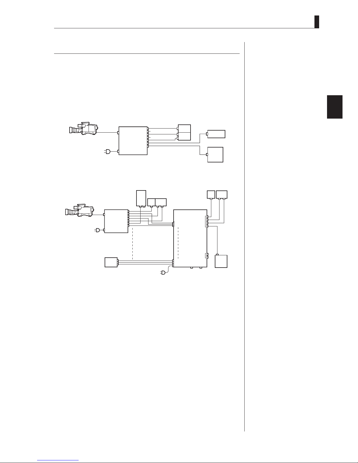
1.2 Operating Systems
1.1 Features of This Product
This product is equipped with functions which interface with a control panel and a control
unit. If you use BSF-55, this product can support not only stand-alone VTR shooting but
also various shooting styles such as studio shooting and field shooting as a system camera.
Furthermore, you can choose and operate each control panel to be connected to the BS, for
your purpose.
■
Example of Minimum Configuration of System Camera (1 camera, 1 OCP, 1 MCP)
Camera Head
BS
■
Example of System Camera Configuration (Up to 8 cameras, 1 MCP)
Camera Head
PM
BS-1
WFM
COMM
BS-8
PM
WFM
COMM
OCP
PM, WFM, COMM
PM
WFM
WFM CONT
PM WFM
WFM, COMM
WFM
CONT
PM
BS-1
BS-8
PM
WFM
CSU
OUT
OCP
MCP
PM WFM
PM
WFM
WFM CONT
COMM
IN
MCP
Note:
By using an SE-H700 system
expander together, this product
can operate as a full-scale studio
camera equipped with a 9-inch
viewfinder and a full studio lens.
Note:
For Minimum operating System,
no MCP needed when OCP-200
is used.
Ter m :
OCP (Operation Control
Panel)
This control panel is used for
normal operation. Typically one
OCP is dedicated to one camera
chain.
Ter m :
MCP (Maintenance Control
Panel)
This control panel is used for
the maintenance and precise
adjustment of the camera in
studio shooting. By using a
memory card, you can save the
shooting condition on memory
and make setup easily. By using a
CSU together with an MCP, you
can maintain up to 32 cameras.
Ter m :
CSU (Camera Select Unit)
Used when controlling multiple
cameras. With using a MCP,
one CSU can control up to 8
cameras, and contains terminals
through which video is output
on the monitor from the selected
camera.
11
OUTLINE
HDK-55 1206 VER1 (U)
5
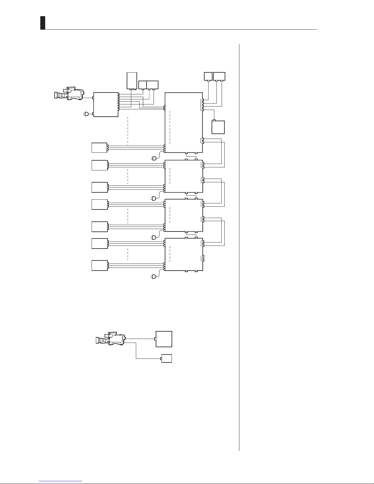
1.2 Operating Systems
■
Example of Minimum Configuration of System Camera
(Up to 32 cameras and 1 MCP)
Camera Head
BS-1
BS-8
BS-9
BS-16
BS-17
BS-24
BS-25
BS-32
PM
WFM
COMM
PM, WFM, COMM
OCP
PM WFM
WFM
CONT
WFM, COMM
PM
BS-1
CSU-1
BS-8
CSU MCP
BS-9
CSU-2
BS-16
CSU MCP
BS-17
CSU-3
BS-24
CSU MCP
BS-25
CSU-4
BS-32
OUT
OUT
OUT
OUT
IN
IN
IN
IN
PM WFM
PM
WFM
COMM
MCP
PM
WFM
PM
WFM
PM
WFM
WFM CONT
■
Example of VTR Location Configuration
(Minimum Configuration of Camera, VTR, and PM)
Camera Head
HD
VTR
PM
6
HDK-55 1206 VER1 (U)
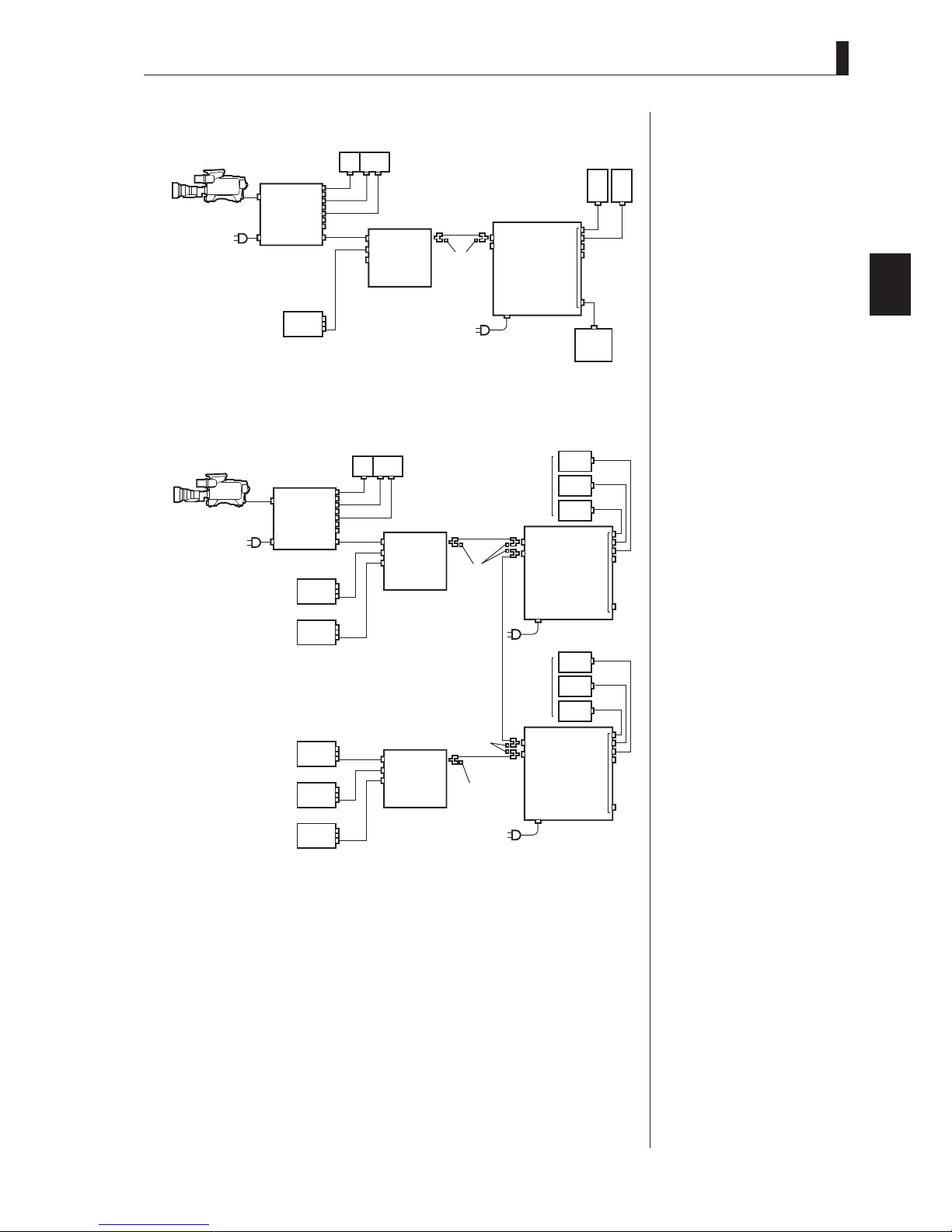
■
Network Connection (Basic bus connection)
1.2 Operating Systems
Camera Head
BS-1
OCP/
CCP
BS-2
■
Network Connection (Expansion bus connection)
Camera Head
BS-1
PM
WFM
BS-2
PM
WFM
OCP/
CCP
PM WFM
CP cable
CP cable
BS/
CCU
BSH-200
PM WFM
BS/
CCU
ARC1
ARC2
ARC3
ARC1
ARC2
ARC3
BSH-200
Coaxial cable
75Ω
termination
Coaxial cable
75Ω
termination
ARC1
ARC2
CPH-200
OCP-200
ARC1
ARC2
CPH-200
CP
OCP-200
CP cable
MCP-200
CP cable
CP
Note:
- The OCP/CCP connector and
MCP/CCP connector on the CCU
cannot be used with the network
connector at the same time in
this configuration.
Ter m :
CPH (Control Panel Hub)
The hub for network used with
connecting to a network-adaptive
control panel.
Ter m :
BSH (Base Station Hub)
It is designed as the HUB unit
of which employs command
converter for Ikegami's nonnetwork capable camea head/
BS/CCU to use under network
control system.
Note:
- The OCP/CCP connector and
MCP/CCP connector on the CCU
cannot be used with the network
connector at the same time in
this configuration.
11
OUTLINE
BS-3
BS-4
BS-5
BS-6
CP cable
BS/
CCU
BSH-200
Coaxial cable
75Ωtermination
ARC1
ARC2
ARC3
75Ωtermination
Coaxial cable
OCP-200
ARC1
ARC2
CP cable
CP
CPH-200
HDK-55 1206 VER1 (U)
7

1.2 Operating Systems
8
HDK-55 1206 VER1 (U)
1
OUTLINE
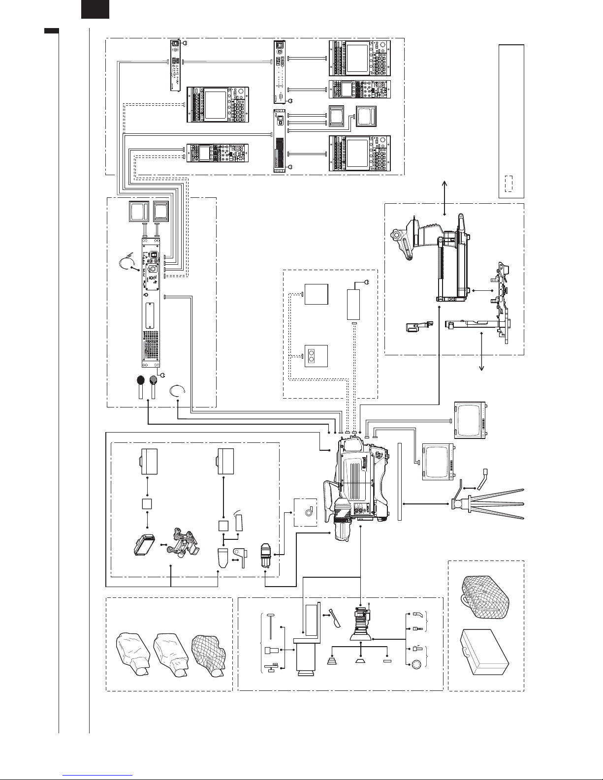
9
AC
Coaxial Cable CP Cable Max. 300m
CP Cable Max. 30m
MCP-200OCP-200
BSH-200E
1.3 Connection Diagram
BSH-200
CPH-200
CPH-200
AC
MCP-200
CP Cable Max.300m
CP Cable Max.80m (*Note 1)
Headset
BSF-55
PM
Base Station
MIC-1
MIC-2
WFM
AC
Max.300m (*Note 1)
Power Cont Cable
Headsets
(PROD/ENG)
Fiber Cable Max.3000m
OCP-200
(*Note 1)
CSU
AC
CP Cable
Max.300m
CP Cable Max. 50m
Coaxial Cable
WFM Cont Cable
Coaxial Cable
(*Note 2)
Max.10m
MCP Cable
HD
VTR
WFM
RCP-50B
POWER
Coaxial Cable
PM
AC
DC Power Cable
DC 11 to DC16V
length is 300m at the maximum.
When OCP-200 is used, the POWER CONT cable cannot
be used.
(*Note 2)
MCP-200
cable length is 30m at the maximum.
Note 1: When any OCP other than OCP-200 is used, the CP cable
Note 2: When any MCP other than MCP-200 is used, the MCP
- 9"LCD VF (VFL912HD (COLOR))
- Script Lamp
- RET SW Box
- Pedestal/Tripod System
SE Main Body
Tally Box
SE-H700
System Expander
- Lens
Coaxial Cable
Multi Video Cable (Analog)
Coaxial Cable (HD SDI)
HD
Monitor
(COLOR)
- Lens Accessory
Equipment inside the dotted frame is mainly
used for stand-alone/VTR location shooting.
Lens Supporter
1.3 Connection Diagram
9-inch LCD VF
VF System
Cover
Studio Hood
(VFL912HD)
Dust Proof
Cover
Carrying Case
Rain Proof
Cover
Attachment
5-inch VF
(VF13XHD)
Cold Weather
Cover
Studio Hood
Carrying Case
Field Hood
Attachment
Lens
Standard VF
Manual Control
Mic Holder
2-inch VF (VF421HD, VFL200HD)
Adaptor
Prompter
Zoom Lens
FA-55
Teleside
Converter
Script
Lamp
HDK-55
Zoom Lens
Wide
12Pin
Attachment
W/Diascope
or
W/O Diascope
Filter
Tripod Mount Plate
HD
(B/W)
Monitor
Remote Zoom
Control Set
Remote Focus
Control Set
Tripod
Case
Zoom Remote
Control Box
Camera Carrying Case Soft Carrying Case
HDK-55 1206 VER1 (U)


NAME and FUNCTION
2

12
HDK-55 1206 VER1 (U)
2.1 Camera and Viewfinder
This section explains the names and functions of the parts on the camera and viewfinder.
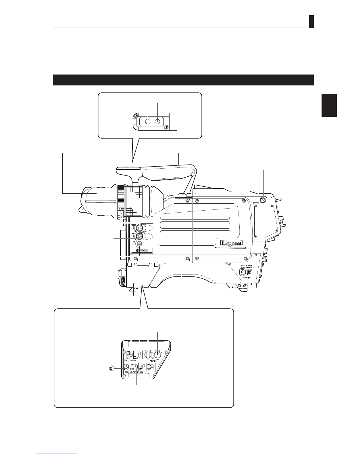
Camera Right View
2.1 Camera and Viewfinder
RET-2/MIC button ③
① Viewfinder(VF)
INCOM PHONE ⑪
control knob
INCOM PGM ⑩
control knob
INCOM MIC button ⑨
④ RET-1 button
/+%
4'6
4'6
2
NAME and FUNCTION
② Handle
⑤ Shoulder belt hook
Switch control ⑫
panel cover
FILTER HEAD switch ⑭
SHUTT/SUP-V switch ⑬
GAIN SELECT switch
OUTPUT SELECT switch ⑳
⑧ Shoulder pad
⑮ CC FILTER switch (ECC)
⑯ ND FILTER switch
⑰ FILTER local indicator
⑱ AWB/ABB switch
⑲ AWB SELECT switch
HDK-55 1206 VER1 (U)
⑥ POWER indicator
⑦ POWER switch
13

2.1 Camera and Viewfinder
Viewfinder (VF)
①
Displays camera image, return image, various characters and markers. A 2" viewfi nder, an
optional 5" high definition B/W viewfinder, and an optional 9" LCD color viewfinder are
available.
Handle
②
Grip this handle to carry the camera.
RET-2/MIC button
③
The RET-2 switch function or INCOM MIC switch function is allocated to this button. The
button selects the function or turns ON/OFF the function.
When set to RET-2
●
The viewfinder image is switched from the camera image to RET-2 image while this button
is pressed.
When set to INCOM MIC
●
Turns the intercom microphone ON/OFF when the INCOM FRONT VR SELECT switch on
the rear of the camera is set to "ENG" or "PROD". The intercom microphone is turned ON
while this button is pressed.
RET-1 button
④
Switches the viewfi nder image from the camera image to RET-1 image. The viewfinder
image is switched to the RET-1 image while this button is pressed.
Shoulder belt hook
⑤
Attaches the optional shoulder belt.
POWER indicator
⑥
Displays the stat us of power supply to the camera
Green LED : Indicates power is on
Red LED : Indicates power is in standby
POWER switch
⑦
Turns ON/OFF the power of the camera or switches the power supply.
BS/CCU : Supplies power from the BS to the camera via fiber cable.
OFF : Turns power OFF.
EXT : Supplies power from external power supply. Set the POWER switch to EXT
when power is supplied from exter nal power through DC IN connector in the
self-contained or VTR location operation.
Reference:
The functions are allocated using
the menu. Refer to "5. CAMERA
SETTINGS and ADJUSTMENT",
"Menu Configuration and
content" (page 83) for setting.
Shoulder pad
⑧
Put the shoulder pad on your shoulder when you carry the camera on your shoulder.
INCOM MIC button
⑨
Turns the intercom microphone ON/OFF when the INCOM FRONT VR SELECT switch on
the rear of the camera is set to "ENG" or "PROD". The intercom microphone is turned ON
while this button is pressed.
INCOM PGM control knob
⑩
Controls the PGM volume of the intercom when the INCOM FRONT VR SELECT switch
on the rear of the camera is set to "ENG" or "PROD".
INCOM PHONE control knob
⑪
Controls the volume of the intercom when the INCOM FRONT VR SELECT switch on the
rear of the camera is set to "ENG" or "PROD".
Switch control panel cover
⑫
Protects the switch control panel.
14
HDK-55 1206 VER1 (U)
 Loading...