

Ikegami CCU-890 Operation Manual

Products conforming to RoHS directive
Cam era Control Unit
CCU-890
OPERATION MANUAL


0804 2nd Edition (U) (E)
1
OUTLINE
2
NAME and FUNCTION
Camera Control Unit
OPERATION MANUAL
3
FORMATS and GENLOCK
5
CCU SETTINGS and
ADJUSTMENT
6
TROUBLE SHOOTING and
MAINTENANCE
CHANGING INFORMATION
4
EQUIPMENT
CONNECTIONS
CCU-890
Products conforming to RoHS directive
Copyright © 2008 Ikegami Tsushinki Co., Ltd.
Copyright © 2008 Ikegami Tsushinki Co., Ltd.
We reserve the copyright on the software we create.
We reserve the copyright on the software we create.
No part of this publication may be modifi ed or reproduced in any form, or by any means, without prior written permission from Ikegami
No part of this publication may be modifi ed or reproduced in any form, or by any means, without prior written permission from Ikegami
Tsushinki Co., Ltd.
Tsushinki Co., Ltd.

PRODUCTS CONFORMING TO RoHS DIRECTIVE
CCU-890 0804 VER2 (U) (E)
i
PRODUCTS CONFORMING TO RoHS DIRECTIVE
PRODUCTS CONFORMING TO RoHS DIRECTIVE
Following products described in this manual are products conforming to RoHS directive.
• CCU-890 Camera Control Unit
Products conforming to RoHS directive include products that do not contain specifi ed hazardous substances such as lead, mercury,
cadmium, hexavalent chromium, polybrominated biphenyl (PBB) and polybrominated diphenyl ether (PBDE) in electrical and
electronic equipment excluding following exemption applications based on the EU directive (Directive2002/95/EC).
*
About RoHS Directive
The RoHS directive stands for "the Restriction of the Use of Certain Hazardous Substances in Electrical and Electronic Equipment"
and is one of environmental directives in Europe. This directive restricts the use of specifi ed hazardous substances in electrical and
electronic equipment.
䃂
Applications exempted from RoHS directive compliance
Followings applications are permitted as exemptions from RoHS directive compliance.
1. Mercury in compact fl uorescent lamps not exceeding 5mg per lamp
2. Mercury in straight fl uorescent lamps for general purposes not exceeding:
•halophosphate 10mg
•triphosphate with a normal lifetime 5mg
•triphosphate with a long lifetime 8mg
3. Mercury in straight fl uorescent lamps for special purposes
4. Mercury in other lamps not specifi cally mentioned in this Annex
5. Lead in the glass of cathode ray tubes, electronic components and fl uorescent tubes
6. Lead as an alloying element in steel containing up to 0.35% lead by weight, aluminum containing up to 0.4% lead by weight
and as a copper alloy containing up to 4% lead by weight
7. Lead in following items
•Lead in high melting temperature type solders (i.e. tin-lead solder alloys containing more than 85% lead)
•Lead in solders for servers, storage and storage array systems
•Lead in solders for network infrastructure equipment for switching, signaling, transmission as well as network management
for telecom mun ication
•Lead in electronic ceramic parts (e.g. piezoelectronic devices)
8. Cadmium plating except for applications banned under Directive 91/338/EEC amending Directive 76/769/EEC relating to
restrictions on the marketing and use of certain dangerous substances and preparations
9. Hexavalent chromium as an anti-corrosion of the carbon steel cooling system in absorption refrigerators
10. Lead used in compliant pin connector systems
11. Lead as a coating material for the thermal conduction module C-ring
12. Lead and cadmium in optical and fi lter glass
13. Lead in solders consisting of more than two elements for the connection between the pins and the package of microprocessors
with a lead content of more than 80% and less than 85% by weight
14. Lead in solders to complete a viable electrical connection between semiconductor die and carrier within integrated circuit Flip
Chip packages
15. Decabrominated diphenyl ether (Deca-BDE) in polymeric applications

MAINTENANCE OF PRODUCTS CONFORMING TO RoHS DIRECTIVE
ii
CCU-890 0804 VER2 (U) (E)
MAINTENANCE OF PRODUCTS CONFORMING TO RoHS DIRECTIVE
MAINTENANCE OF PRODUCTS CONFORMING TO RoHS DIRECTIVE
Work with care about followings for maintenance of products conforming to RoHS directive.
1. Identification
- For products conforming to RoHS directive, the letter "E" is appended at the end of the serial number on the label. For models
that the letter cannot be appended to the serial number, the letter "E" will be described in a distinguishable position on the
label. A description example on a main label is shown below.
CAMERA CONTROL UNIT
Product conforming to RoHS directive
Label
- Print-circuit board of the products conforming to RoHS directive is manufactured by following methods.
[1] Blue resist ink is used for the print-circuit board. (The color of conventional print-circuit board is green.)
[2] Either one of the following marks is indicated by a serigraph or label.
Phase 3A Phase 3
2. Soldering
Since the melting point of lead-free solder used for the products conforming to RoHS directive is 20 to 45 degrees Celsius higher
than that of conventional solder with lead (Sn-Pb eutectic solder), a high temperature needs to be set to a soldering iron. Taking
allowable temperature limit of the parts and stable work into consideration, use a soldering iron with excellent thermal recovery
characteristics.
- Recommended solder composition is "Sn/3.0Ag/0.5Cu" or equivalent.
- Separate the soldering iron exclusively for RoHS products and the soldering iron for conventional use.
- Set the temperature of the soldering bit to 350 to 370 degrees Celsius.
The temperature may need to be adjusted according to the size of the copper foil land on the print-circuit board and the tip
width of the soldering bit.
- Finish by a lead-free solder looks dull or whitish compared to conventional solder with lead.
- If the customer mixed the lead-solder with the main body wiring or the circuit board, it becomes guarantee off the subject.
Ikegami doesn't guarantee to do the repair work. Because the solder polluted with lead cannot be removed.
3. Parts
Be sure to use parts conforming to RoHS directive.

INFORMATION TO THE USER
CCU-890 0804 VER2 (U) (E)
iii
INFORMATION TO THE USER
INFORMATION TO THE USER
This equipment has been tested and found to comply with the limits for a Class A digital device, pursuant to Part 15 of the FCC
Rules. These limits are designed to provide reasonable protection against harmful interference when the equipment is operated in a
commercial environment. This equipment generates, uses, and can radiate radio frequency energy and, if not installed and used in
accordance with the instruction manual, may cause harmful interference to radio communications.
Operation of this equipment in a residential area is likely to cause harmful interference in which case the user will be required to
correct the interference at his own expense.
Changes or modifi cations not expressly approved by the party responsible for compliance could void the user's authority to operate
the equipment.
SAFETY PRECAUTIONS
iv
CCU-890 0804 VER2 (U) (E)
SAFETY PRECAUTIONS
SAFETY PRECAUTIONS
This manual describes the precautions using various pictorial symbols for you to use the product safely. Please read these
precautions thoroughly before use. The symbols and meanings are as follows:
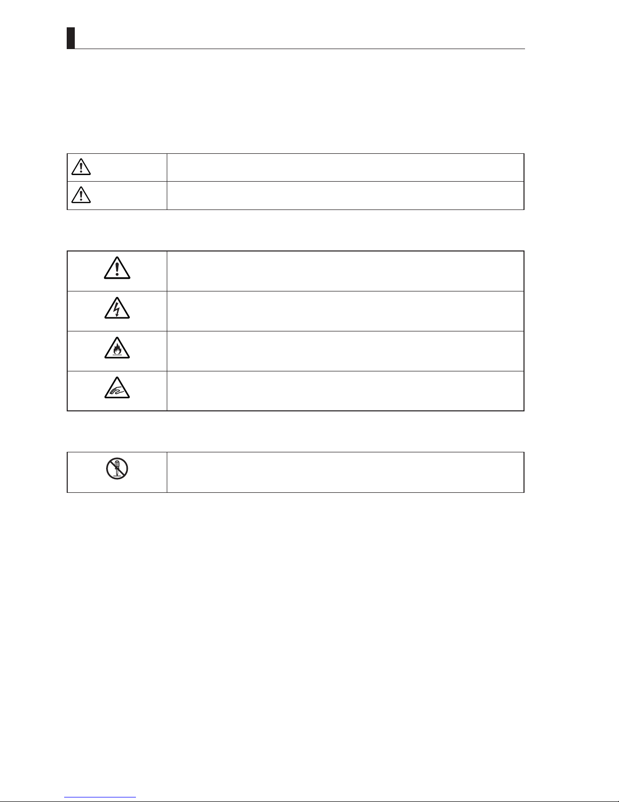
The following hazard alert symbols are used to indicate the level of impact on the body or property
when you do not follow the precautions.
WARNING
Indicates that mishandling of the product by ignoring this label may lead to a danger resulting in a
serious injury or death.
CAUTION
Indicates that mishandling of the product by ignoring this label may lead to a danger resulting in an
injury or property damage.
The following symbols are used to indicate the expected injury or hazards when you do not follow
the precautions.
Indicates general cautions on such matters as safe work, procedure, and installation location.
Mishandling may not directly lead to death, injury, or property damage.
Indicates that mishandling may cause an electric shock.
Indicates that mishandling may cause a fi re.
Indicates that mishandling may cause injury.
The following symbol is used to indicate other precautions to prevent damage or hazard from
occurring:
Indicates prohibited action.
SAFETY PRECAUTIONS
CCU-890 0804 VER2 (U) (E)
v
䂓
Handling Precautions
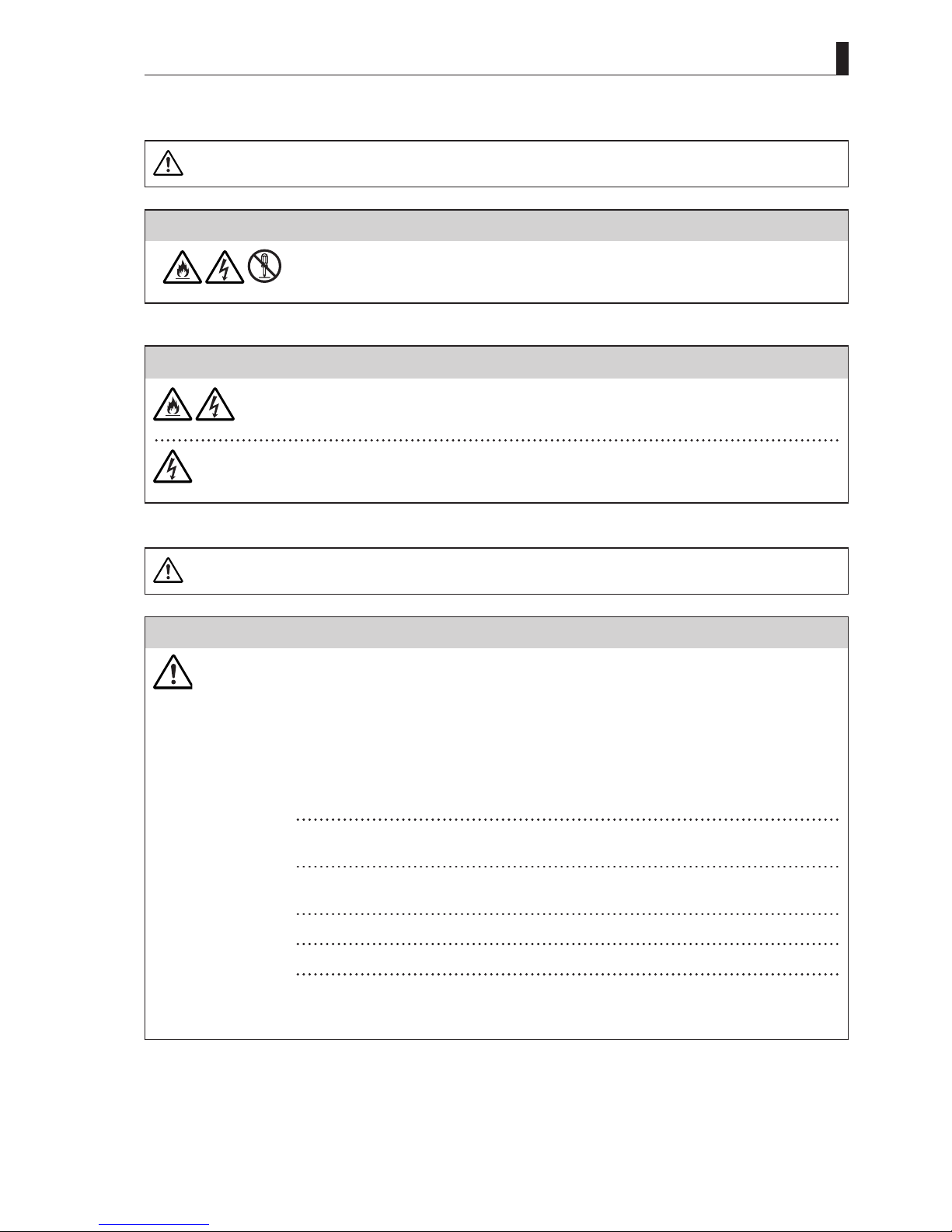
WARNING
Regarding the Product
Do not disassemble or modify the product which is not described in this manual. Doing so may
cause fi re, electric shock, or injury.
Regarding the Power
When you disconnect the cable, be sure to hold the plug and pull. Failure to do so may cause a fi re
or electric shock due to a damaged cable.
To inspect or operate on the inside of the equipment, turn off the power and wait for one or two
minutes before starting work. High voltage is present in some modules and connectors of this
product.
CAUTION
Regarding the Product
Avoid use or storage in the following conditions:
- Extremely high/low temperature
- In direct sunlight for a long time, or near a heater
- High humidity or dusty
- Exposed to water or other liquid
- Strong vibration or shock
- Strong magnetic fi eld or radio waves
- lightning
- In rain without the rain cover
Be sure to hold the plug and pull when you disconnect the cable.
Condensation that cause malfunction may occur in the equipment.
Avoid moving the equipment suddenly from an extremely cold place to a warm place.
Condensation may occur in the Charged Couple Device (CCD) or other parts.
Do not drop or insert a metal object such as a pin or a foreign object into the equipment.
Do not spread or spill water or other liquid on the equipment.
Do not subject the equipment to a strong shock or vibration.
Doing so may cause damage or malfunction of the equipment.
Excessive sound pressure from the headset may cause a hearing loss.

SAFETY PRECAUTIONS
vi
CCU-890 0804 VER2 (U) (E)
Regarding the Modules
Pay attention to the following points when handling the modules:
- Do not let the parts of the modules or the printed wiring pattern to touch the metal parts that can
be energized.
- Avoid placing or storing the modules in humid places.
- Do not touch the parts of the modules or the printed wiring pattern with dirty or wet hands. Do
not touch them with hands unless necessary.
Regarding the Power and the Lithium Battery
Use the product in compliance with the rating of the fuse. Otherwise, a fault can occur.
Do not use an unspecifi ed battery.
Wrong usage of batteries may cause liquid leak, explosion, and heat, and at worst injury or fi re.
When changing or discarding a battery, please contact Ikegami's sales and service centers.
䂓
Maintenance
Regarding the product
Before performing maintenance on the product, be sure to turn off the power for safety and for
protection against malfunction.
Clean the product using a dry and soft cloth.
If the product is very dirty, wipe with a cloth moistened with water or neutral detergent and wrung
out. If neutral detergent is used, wipe again with a cloth dipped in clear water and wrung out.
䂓
Regular Maintenance Recommended
This product includes parts that wear out and have a limited life even in proper use or storage. Therefore, regular maintenance
(once every 3 years or 8000 hours use) is recommended to extend the life and safe use of this product for a long time. Please contact
Ikegami's sales and service centers or Techno Ikegami Co., Ltd. for the regular maintenance and repair of our products.
DOCUMENTATION FOR THE PURCHASER/USER
CCU-890 0804 VER2 (U) (E)
vii
DOCUMENTATION FOR THE PURCHASER/USER
DOCUMENTATION FOR THE PURCHASER/USER
1. Declaration of conformity
The CE mark means that the following products will meet the Directive 2004/108/EC,2006/95/EC and the Standards
EN55103-1 E4, E5 EN55103-2 E4, E5 (for EMC), EN60950-1 (for LVD).
For European customer.
2. Please use it by less than 10m, when you use cable of MIC1 OUT, MIC2 OUT, AUD TRUNK, INTERCOM, and DIGITAL
AUDIO.
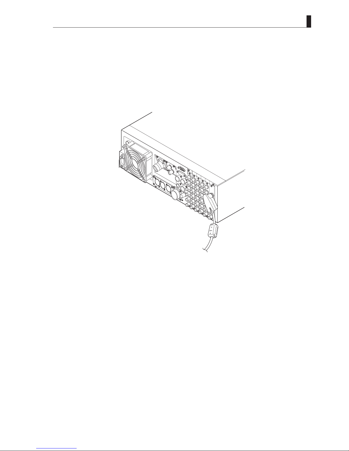
3. Please wind the core which is attached to the cable, when the coaxial cable is used for the Network connector.
(Please refer to the fi g.1)
fi g.1 (core type: E04SR200935A)
4. We carried out a test in accordance with EN55103-1 Annex B.
As a result, the value of the inrush current is as follows.
inrush current
CCU-890+HDK-79EX3+SE-H700+OCP-200+MCP-200 16.32A

HOW TO READ THE OPERATION MANUAL
viii
CCU-890 0804 VER2 (U) (E)
HOW TO READ THE OPERATION MANUAL
HOW TO READ THE OPERATION MANUAL
This page explains general notes on reading the CCU-890 Operation Manual, and the symbols and notations used in the manual.
䂓
Notes on the Manual
- This manual is written for readers with a basic knowledge of handling a broadcast camera, CCU, or MCP.
- The contents of this manual are subject to change without notice in the future.
䂓
Symbols
The symbols used in this manual are as follows:
CAUTION:
Things you have to be careful during operation. Be sure to read.
Note:
Supplementary information or guidance
Reference:
Sections where related information is available
䂓
Notations
The following notations are used in this manual.
This product, CCU Indicates CCU-890 Camera Control Unit.
Camera head Indicates general broadcast cameras.
䂓
Illustrations and Displays
The illustrations and displays in the text are provided for explanation and may be slightly different from the actual equipment or
image.
䂓
Related Manuals
Refer to the operation manuals and maintenance manuals accompanying the camera head, CCU, and each control panel to be used.

HOW TO READ THE OPERATION MANUAL
CCU-890 0804 VER2 (U) (E)
ix
Structure of Operation Manual
CCU-890 Camera Control Unit Operation Manual is intended to both safely and smoothly operate the CCU-890. The Operation
Manual consists of fi ve chapters. By reading it in sequence, you can smoothly perform a series of steps, from connection to
operation.
Chapter 1
Chapter 3
Chapter 5
Chapter 3
Chapter 4
Chapter 6
Chapter 2
OUTLINE
Explains the features and the specifi cations of this product.
If you are not familiar with CCU-890, please start with this chapter.
NAME and FUNCTION
Explains the name and function of each part of the CCU-890.
FORMATS and GENLOCK
Explains the signal formats of the CCU-890 and DUAL LINK specifi cation.
EQUIPMENT CONNECTIONS
Explains how to connect the CCU-890 to monitor, camera head, and so on.
Also explains how to connect this product to camera and the peripheral equipment and examples to
operate this product.
CCU SETTINGS and ADJUSTMENT
Explains the menu of the CCU-890 and DIP switch settings on the modules inside of the CCU.
TROUBLE SHOOTING and MAINTENANCE
CCU-890 is equipped with the self-diagnostic function. When the alarm lamp lights during the
operation of this product, read here to know the problem. This chapter also explains the regular
maintenance such as cleaning of connectors and replacement of fuses.
CHANGING INFORMATION
This manual is written for the standard specifi cations. Your custom specifi cations and revision
information are addressed in "CHANGING INFORMATION." Read by comparing with the main text
of the maintenance manual. ("CHANGING INFORMATION" may be sent to you later on.).

CONTENTS
x
CCU-890 0804 VER2 (U) (E)
CCU-890
CAMERA CONTROL UNIT
OPERATION MANUAL
PRODUCTS CONFORMING TO RoHS DIRECTIVE . . i
INFORMATION TO THE USER . . . . . . . . . . . . . . . . . . iii
SAFETY PRECAUTIONS . . . . . . . . . . . . . . . . . . . . . . . iv
HOW TO READ THE OPERATION MANUAL . . . . . . .viii
Chapter 1 OUTLINE
1.1 Features of This Product . . . . . . . . . . . . . . . . . 3
1.2 Specifi cations . . . . . . . . . . . . . . . . . . . . . . . . . . 4
1.3 External Dimensions Diagram . . . . . . . . . . . . . 7
Chapter 2 NAME and FUNCTION
2.1 CCU-890 Front View . . . . . . . . . . . . . . . . . . . 11
CCU-890 Front View With the Front Cover On
. . . . . . . . . . . . . . . . . . . . . . . . . . . . . . . . . . . . 11
CCU-890 Front View With the Front Cover Off
. . . . . . . . . . . . . . . . . . . . . . . . . . . . . . . . . . . . 14
2.2 CCU-890 Rear View . . . . . . . . . . . . . . . . . . . . 17
Modules on the Rear of the CCU-890 . . . . . . 19
Chapter 3
FORMATS and GENLOCK
3.1 HDTV Format . . . . . . . . . . . . . . . . . . . . . . . . . 25
3.2 GENLOCK System . . . . . . . . . . . . . . . . . . . . . 26
Input Connectors . . . . . . . . . . . . . . . . . . . . . . 26
Output Connectors . . . . . . . . . . . . . . . . . . . . . 26
3.3 DUAL LINK (HS TYPE) Specifi cation for the
CCU . . . . . . . . . . . . . . . . . . . . . . . . . . . . . . . . 32
Rear Module Confi guration at DUAL LINK
(HS TYPE) Specifi cation . . . . . . . . . . . . . . . . 33
Video Format Available for DUAL LINK
(HS TYPE) Specifi cation . . . . . . . . . . . . . . . . 35
Chapter 4
EQUIPMENT CONNECTIONS
4.1 Preparation . . . . . . . . . . . . . . . . . . . . . . . . . . . 39
Product Use Environment . . . . . . . . . . . . . . . 39
Make sure the Power Switch is OFF . . . . . . . 39
4.2 Power Supply . . . . . . . . . . . . . . . . . . . . . . . . . 40
4.3 CCU and Camera Head Connection . . . . . . . 43
4.4 System Setup Diagram . . . . . . . . . . . . . . . . . 44
4.5 Operating Systems . . . . . . . . . . . . . . . . . . . . . 46
4.6 External Connections . . . . . . . . . . . . . . . . . . . 49
Chapter 5
CCU SETTINGS and ADJUSTMENT
5.1 Settings from the CCU Menu . . . . . . . . . . . . . 67
Basic Operation of the Menu
(Operation from the MCP) . . . . . . . . . . . . . . . 67
Basic Operation of the Menu
(Operation from the OCP-200). . . . . . . . . . . . 69
Menu Confi guration . . . . . . . . . . . . . . . . . . . . 71
BARS TITLE . . . . . . . . . . . . . . . . . . . . . . . . . . 73
HDTV CONT (1/2) . . . . . . . . . . . . . . . . . . . . . 73
HDTV PM DISPLAY1 . . . . . . . . . . . . . . . . . . . 75
HDTV PM DISPLAY2 . . . . . . . . . . . . . . . . . . . 75
HDTV CONT (2/2) . . . . . . . . . . . . . . . . . . . . . 76
DOWN CONV CONT (1/3) . . . . . . . . . . . . . . . 77
DOWN CONV CONT (2/3). . . . . . . . . . . . . . . 78
DOWN CONV CONT (3/3). . . . . . . . . . . . . . . 79
SDTV PM DISPLAY1 . . . . . . . . . . . . . . . . . . . 80
SDTV PM DISPLAY2 . . . . . . . . . . . . . . . . . . . 80
UP CONV CONT (1/2) . . . . . . . . . . . . . . . . . . 81
UP CONV CONT (2/2) . . . . . . . . . . . . . . . . . . 82
VIDEO OUT CONT. . . . . . . . . . . . . . . . . . . . . 83
WFM OUT SEL. . . . . . . . . . . . . . . . . . . . . . . . 84
AUDIO CONT . . . . . . . . . . . . . . . . . . . . . . . . . 85
SETTING SELECT. . . . . . . . . . . . . . . . . . . . . 85
RET VIDEO FORMAT . . . . . . . . . . . . . . . . . . 86
INFORMATION. . . . . . . . . . . . . . . . . . . . . . . . 87
OTHERS (1/2) . . . . . . . . . . . . . . . . . . . . . . . . 88
OTHERS (2/2) . . . . . . . . . . . . . . . . . . . . . . . . 89
HDTV CONT (1/2) . . . . . . . . . . . . . . . . . . . . . 93
VIDEO OUT CONT (DUAL) . . . . . . . . . . . . . . 93
AUDIO CONT . . . . . . . . . . . . . . . . . . . . . . . . . 95
5.2 Settings Using Switches on the Module . . . . 96
Tally Mode Settings . . . . . . . . . . . . . . . . . . . . 96
Intercom Settings . . . . . . . . . . . . . . . . . . . . . . 97
PGM Settings . . . . . . . . . . . . . . . . . . . . . . . . . 98
Chapter 6
TROUBLE SHOOTING and MAINTENANCE
6.1 Indicator on the Front of CCU Lights . . . . . . 101
6.2 ALARM Indicator on the Control Panel Flashes
ON and OFF . . . . . . . . . . . . . . . . . . . . . . . . . 105
CCU Self Diagnostic Information . . . . . . . . . 106
6.3 Replacing Fuses. . . . . . . . . . . . . . . . . . . . . . 111
CHANGING INFORMATION . . . . . . . . . . . . . . . . . . . 113

1
OUTLINE
OUTLINE

2
CCU-890 0804 VER2 (U) (E)

1.1 Features of This Product
CCU-890 0804 VER2 (U) (E)
3
The CCU-890 is a camera control unit to receive high quality images obtained by the camera head without any loss. A camera cable
connects between the CCU and the camera head, and the optical serial digital transmission complies with SMPTE292M (International
standard). A transmission distance of up to 3,000 m* (for portable camera operation) and 2,000m* (for studio camera operation).
This product is equipped with both D/C (down converters) and U/C (up converters), and enables simultaneous output of HDTV
signal and SDTV signal, and therefore simultaneous operation in the HDTV system and the SDTV system is possible. Also, this
product is able to output multiple HDTV-format video in 24P operation.
* The maximum cable length varies according to the type of lens and the use of utility power.
1.1 Features of This Product
䂓
Converter Function
D/C (down converters) and U/C (up converters) for return video are built in to support the SDTV system.
䂓
24P Format Conversion Function
By connecting the HDK-79EC portable camera, native 24P, 24SF, and 2-3PD format signals can be output.
䂓
Audio Signal Embedded in each SDI Output (Embedded Audio Function)
Audio signals can be embedded in SDI signals of the main output, PM output, and WFM output. Audio signals can be embedded in
HD-SDI signals and SD-SDI signals.
䂓
Frame Synchronizer Mounted to RET Signals
In conventional CCUs, the return video must be in sync with the camera video. This product includes a frame synchronizer that
enables synchronization of asynchronous input video for stable return video regardless of synchronous/asynchronous.
* When the frame synchronizer function is enabled, RET input is limited to 2 channels.
䂓
Remote Control to Support Network
In addition to traditional control by serial commands, this product supports control through network connection. Building a system
to support network realizes a wide range of operating confi gurations such as panel assignment. This product can be easily added to
the system to support network since the cables to be used for the network are coaxial cables.
■
Interface for Triax Transmission Equipment
This product mounts an interface for the CB-79HD (CONVERTER BOX) to convert optical transmission into triax transmission.

1.2 Specifi cations
4
CCU-890 0804 VER2 (U) (E)
1.2 Specifi cations
䂓
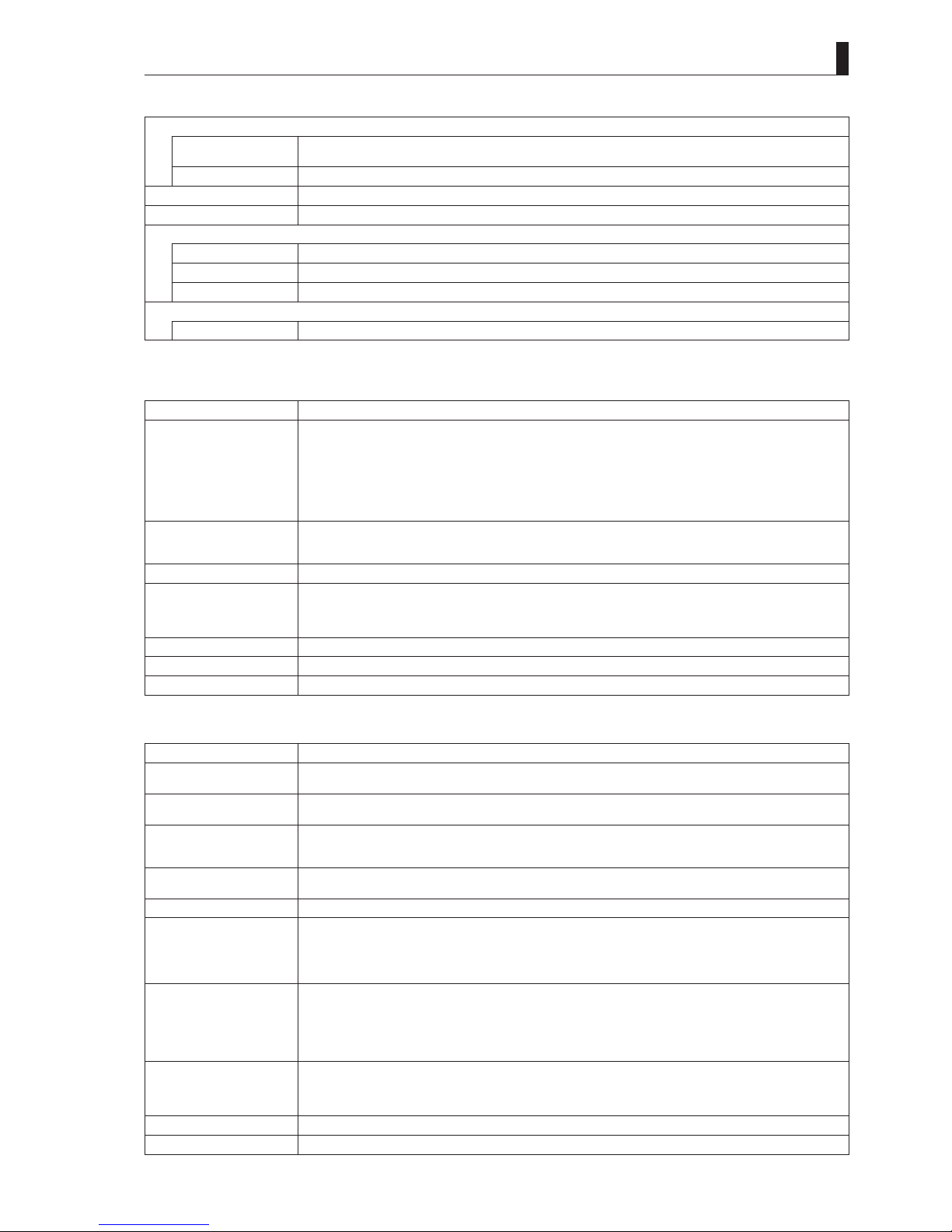
Rating and Performance
CCU output format
Camera head format: 1080I/59.94
- HDTV signal output
1080I/59.94 2:1 interlace
- SDTV signal output
525I /59.94 2:1 i nterlac e
Camera head format: 1080I/59.94 2-3 pulldown
- HDTV signal output
1080I/59.94 2-3 pulldown
1080P/23.98 progressive (Currently not supported)
1080P/23.98 segment frame
- SDTV signal output
525I/59.94 2-3 pulldown
Camera head format: 720P/59.94
- HDTV signal output
720P/ 59.94 progressive
720P/23.98 progressive (Currently not supported)
- SDTV signal output
525I /59.94 2:1 i nterlac e
Camera head format: 1080I/50
- HDTV signal output
1080I/50 2:1 int erlac e
- SDTV signal output
625I/50 2:1 interlace
Camera head format: 720P/50
- HDTV signal output
720P/50 progressive
- SDTV signal output
625I/50 2:1 interlace
Frequency characteristics
HDTV output signal
CCU output of Y, Pb, Pr signals
Output Y signa l Less t han 60 Hz Falling character istic
60 Hz to 30 MHz Within ±1.0 dB
30 MHz or more Falling character istic
Output of Pb and
Pr signals Less tha n 60 Hz Falling characteristic
60 Hz to 15 MHz Within ±1.0 dB
15 MHz or more Falling character istic
SDTV signal output
(when 1080I is
down-converted)
CCU output signal Ych 100 kHz standa rd
Less than 60 Hz Drooping characterist ics
60 Hz to 4.5 MHz Within ±0.5 dB
4.5 MHz to 5 M Hz Within ±1.0 dB
5 MHz or more Drooping character istics
Audio output signal
Less than 100 Hz Falling characteristic
100 Hz to 10 kHz Within ±1.0 dB
10 kHz or more Falling cha racteristic
Performance (when the HDK-79EX is connected)
S/N ratio
(CCU output format:
1080I /59.94)
HDTV : -56dB
NTSC : -6 4dB
Modulation depth
HDTV : Approx. 45% or more (800 TV l ines, 27.5 MHz)
NTSC : Approx. 90% or more (40 0 TV lines, 5 MHz)
Limiting resolution
(CCU output format:
1080I)
HDTV : 1000 TV lines
NTSC : 540 TV lines ( ENC output)
Limiting resolution
(CCU output format:
720P)
HDTV : 700 TV lines
NTSC : 480 TV lines (ENC output)
(when the HDK-727P is connected)
Power
Power voltage
AC 100/110/117/220/234V ±10%
Power consumption
CCU-890 alone
Approx. 100VA
HDK-79E/79E X/79EXⅡ/79EXⅢ/79EC+2-inch B/W V F (VF46HD series) +CCU-890
400 VA or less
HDK-790E/790EXⅢ+7-inch COLOR VF (VFC179HD) +CCU-890
500 VA or less
(Utility power for the camera head is excluded f rom the above voltage value.)
1.2 Specifi cations
CCU-890 0804 VER2 (U) (E)
5
Environmental conditions
Ambient temperature
Operating temperature : 0°C to +45°C
Storage temperature : -30°C to +60°C
Ambient humidity
30% to 90 % without condensation
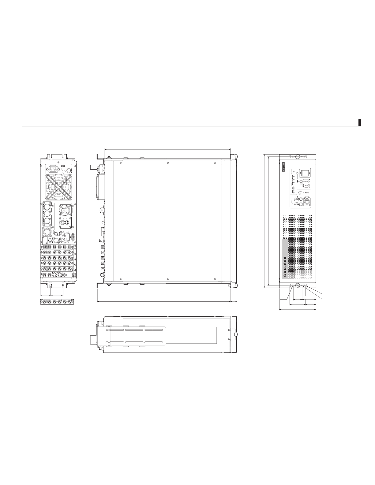
External dimensions
W48 3×H 133× D45 4
Weight
Approx. 28 kg
Applied Standards
EMC standard
FCC15 Subpart B Cla ss A/EN55103-1, EN55103-2
Safety standard
EN60950-1
Quality control
ISO 9001 (JIS Z 9901)
Usage Conditions
Applicable standard
SMPTE 292M, 296M
* The specifi cation indicates the performance when the HDK-79EX series (1080I/59.94 format for the camera head) are connected.
䂓
Input Signals
Item Rating
GENLOCK signal
(HDTV/SDTV supported)
HDTV : PS 1Vp-p 75 bridged connection
or
Tri-sync signal 0.6Vp -p ± 6dB 75 bridged connection
SDTV : VBS 1Vp-p 75 bridged connection
or
BBS 75 bridged connection
or
BBS+10FIELD ID 75 bridged connection
Return signal
HD-SDI 4 channels* 75 single end input
SD-SDI/ VBS (option) selection
4 cha nnels (2 chan nels option) 75 single end input
Q-TV signal
VBS 2 cha nnels 1Vp-p 75 single end input
Intercom signal
(ENG/PROD)
Select from 4-wire/ Clearcom/RTS
4-wire 2 cha nnels 0dBm 600
Clearcom 2 channels -15d Bs 200
RTS 2 cha nnels 0dBm 200
PGM (Program sound)
0dBs standard 2 channels 600/10k
AUDIO TRUNK
0dBs standard 1 channel 600/10k
Tal l y s i gna l
R TALLY, G TALLY Select from MAKE/ BREAK or POWER supply
* 2 channels when the frame synchron izer function is enabled.
䂓
Output Signals
Item Rating
HD-SDI signal
HD-SDI 4 channels 75 output
(BTA S-004B standard)
SD-SDI signal
SD-SDI 2 channels 75 output
(SMPTE259M standard)
Synchronization signal
HDTV/SDTV selection 1 channel 75 output
HDTV tri-sync signal 0.6Vp-p
SDTV 2Vp-p
Component signal
Select a pair from HDTV GBR/YPbPr, SDTV GBR/ YCbCr
1 channel 75 output
Composite signal
VBS 2 cha nnels 1Vp-p 75 output
Picture monitor (PM) signal
HD-SDI (R/G /B/ Y/ENC) 2 channels 75 output
(BTA S-004B standard)
Select from SD -SDI/SDTV analog signal (R /G /B/ Y/ENC)
(SMPTE259M standard for SD-SDI signal)
2 cha nnels 75 output
Waveform monitor (WFM)
signal
HD-SDI
(BTA S-004B standard)
2 cha nnels 75 output
Select from SD -SDI/SDTV analog signal (R /G /B/ Y/ENC for analog signal)
(SMPTE259M standard for SD-SDI signal)
2 cha nnels 75 output
Intercom signal
(ENG/PROD)
Select from 4-wire/ Clearcom/RTS
4-wire 2 channels 600
Clearcom 2 channels 200
RTS 2 cha nnels 200
MIC signal
0dBs standard 2 channels Low impedance
Tal l y s i gna l
R TALLY, G TALLY

1.2 Specifi cations
6
CCU-890 0804 VER2 (U) (E)
䂓
Camera Cable
Standard cable
2SM-9.2-37.5
Cable for studio shooting
2SM-16 -37.5
Cable confi guration
2 single-mode quartz fi ber optic cables
(HEA D -> CCU, CCU -> HEAD one cable for each)
4 power cables (One cable has 37.5/km.)
2 control cables (One cable has 113/km.)
CCU-890 0804 VER2 (U) (E)
7
1.3 External Dimensions Diagram
1.3 External Dimensions Diagram
44.5
±0.2
37.7
±0.2
480〜680 (24)
453.6
±1
482.6
±0.4
465
±0.2
132.6
±0.4
57.2
±0.2
2-φ5.2
2-φ7
4-φ7×10
37.7
±0.2
31.8
±0.2
50.4
±0.2


2
NAME and FUNCTION
NAME and FUNCTION

10
CCU-890 0804 VER2 (U) (E)
2.1 CCU-890 Front View
CCU-890 0804 VER2 (U) (E)
11
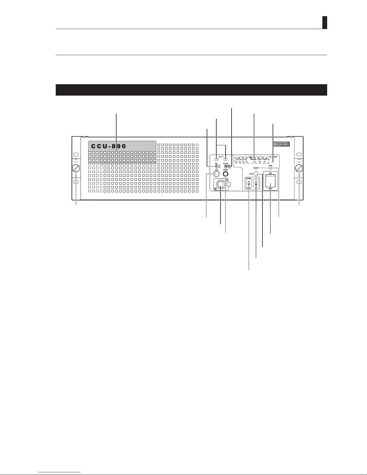
2.1 CCU-890 Front View
This section explains the names and functions of the parts on the front of the CCU-890.
CCU-890 Front View With the Front Cover On
⑥ FAN ALARM
indicator
⑩ HEAD POWER switch
⑪ POWER LOCAL/REMOTE
switch
TALLY indicators ③
INCOM MIC switch ②
⑤ CABLE indicator
⑦
CCU MAIN
POWER indicato
r
⑨
HEAD POWER indicator
⑧
CCU MAIN POWER
switch
INCOM connector ⑬
INCOM PHONE knob ⑫
CALL switch ⑭
Front cover ①
INCOM COMMON/PRIVATE switch ④
Cover fixing screw Cover fixing screw
①
Front cover
Protection cover on the front of the CCU.
Remove the cover when you need to operate the switches on the front of the module. It is usually used with the cover on.
How to remove/install the front cover
To remove the front cover, loosen the fi xing screws on both ends of the cover and pull the cover straight off. To install the cover,
place the cover in the appropriate position and tighten the screws.
②
INCOM MIC switch
Selects ON/OFF/PTT for the intercom microphone.
ON : Turns ON the intercom microphone.
OFF : Turns OFF the intercom microphone.
PTT : Turns ON the intercom microphone while this switch is pressed down.
(Press To Talk)
③
TAL LY ind icato r s
Indicators for R TALLY and G TALLY.
R TALLY : Lights when the R TALLY signal is input to the TALLY IN connector on the rear of the CCU. It also lights while
the CALL switch on the camera head or on any control panel (such as OCP, MCP, and RCP) is pressed.
G TALLY : Lights when the G TALLY signal is input to the TALLY IN connector on the rear of the CCU.
2.1 CCU-890 Front View
12
CCU-890 0804 VER2 (U) (E)
④
INCOM COMMON/PRIVATE switch
Selects the intercom conversation mode.
COMM : Conversation among the camera head, CCU, and system is enabled.
PRIV : Conversation between the camera head and CCU is enabled.
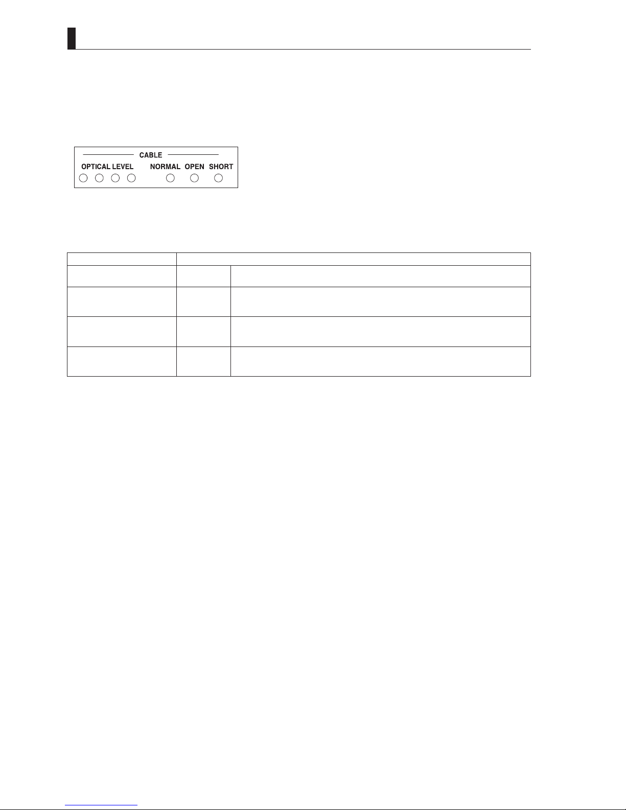
⑤
CABLE indicators
OPTICAL LEVEL indicators
Lighting status varies according to the light reception status of the camera to CCU fi ber transmission path. The table below shows
indicates status.
Lighting Status Light Reception Status
Red Yellow Green Green
䃂䂾䂾䂾
OK Light reception status is good.
Red Yellow Green Green
䃂䂾䂾䃂
ATTENTION The light reception level is low.
Although there is no problem with the reception of signals transmitted, cleaning the fi ber
connector is may be required, unless attenuation is due to very long cable length.
Red Yellow Green Green
䃂䂾䃂䃂
WARNING The light reception level is ver y low.
There might be a problem with the reception of signals transmitted. Immediate cleaning
the fi ber connector is recommended.
Red Yellow Green Green
䂾䃂䃂䃂
NG The light cannot be received.
There is a problem with the reception of signals transmitted. Cleaning the fi ber connector
is required; or replace the cable since the camera cable might be broken.
(䂾: ON/䃂: OFF)
CABLE indicator
Indicates the status of the camera cable.
NORMAL (green) : Lights when the status is normal.
OPEN (red) : Lights when the camera cable is not connected or there is an "open" in the camera cable.
SHORT (red) : Lights when a short circuit occurs in the camera cable or in the camera connector due to a cause such as
water.
⑥
FAN ALARM indicator (red)
Lights when one of the fan motors on the rear of the CCU (1 motor) and inside the CCU (2 motors) has stopped.
⑦
CCU MAIN POWER indicator (green)
Lights when the CCU main power is ON.
⑧
CCU MAIN POWER switch
Switch to turn ON/OFF the CCU main power.
⑨
HEAD POWER indicator
Lights when power is supplied from the CCU to the camera head.
⑩
HEAD POWER switch
Switch to turn ON/OFF the power supply from the CCU to the camera head.
⑪
POWER LOCAL/REMOTE switch
Selects the ON/ OFF mode of the CCU main power.
LOCAL : Main power can be turned ON/OFF from the MAIN POWER switch of the CCU.
REMOTE : When the CCU MAIN POWER switch is "ON," CCU main power and the power of the camera head can be
turned ON/OFF from the OCP.
* In this case, support status for the power ON/OFF of the camera head and CCU vary according to the OCP to be used. Refer to
the instructions accompanying the OCP to be used.

2.1 CCU-890 Front View
CCU-890 0804 VER2 (U) (E)
13
⑫
INCOM PHONE knob
Controls the volume of the intercom receiver.
⑬
INCOM connector
Connects the intercom headset. The connector type varies according to the specifi cation.
⑭
CALL switch
Only while this switch is pressed, the R TALLY indicators on the camera head and the control panel light.

2.1 CCU-890 Front View
14
CCU-890 0804 VER2 (U) (E)
CCU-890 Front View With the Front Cover Off
AC line fuses for transmitting power to the camera head ②
③ Group of modules
CCU MAIN POWER fuse ①
②
①
CCU MAIN POWER fuse
Fuse for the CCU main power.
Fuse to be used
100V-117V AC input voltage: 250V T10A (rating)
220V-240V AC input voltage: 250V T5A (rating)
("T" in the rating indicates a time lag fuse.)
②
AC line fuses for transmitting power to the camera head
Fuse for AC power line to transmit the power to the camera head. Fuses are inserted to each line on 4 taps.
Fuse to be used (fuses are all the same.)
250V T5A (rating)
("T" in the rating indicates a time lag fuse.)
③
Group of modules
PULSE
SDTV RET
HDTV RET
TRX
HDTV PROC
SDTV PROC
AUX- A
①
③
④
⑤
⑥
⑧
②
⑨
⑩
⑪
⑫
⑬
⑭
⑮⑮
⑦
PULSE
module
SDTV RET
module
HDTV RET
module
TRX
module
SDTV PROC
module
E/O&O/E
module
HDTV PROC
module
AUX-A
module
⑮⑯
⑰
CAUTION:
- The TRX module is connected to the E/O&O/E module with a coaxial cable. When inserting/removing modules, be careful not to
catch or hang the cable in other modules.
- The E/O&O/E module is connected to the CCU main body with a fi ber optic cable. Do not remove the cable except for the case to
replace the module.

2.1 CCU-890 Front View
CCU-890 0804 VER2 (U) (E)
15
䂓㩷
PULSE Module
①
GENLOCK indicator
Lights when the CCU operates in GENLOCK mode (external synchronization).
②
Network ID set switches
These 2 rotary switches set the network ID. Values on each switch are expressed in hexadecimal. The upper switch is for the higher
bit; the lower switch is for the lower bit. Set the network ID from 01h to FFh (1 to 255 in decimal number). For details, refer to the
instructions accompanying the HUB to be used.
CAUTION:
Each network ID must be unique in the same network. When the network IDs duplicate, malfunction may occur in not only the
equipment with duplicated IDs but also equipment connected to the same network.
③
MENU switch
Switch to display, confi rm, and end the menu.
④
SELECT switch
Switch to select the menu.
⑤
Do not select this switch while setting this switch to "CP" (factory shipment status).
⑥
HDTV HD test point
Test point for the HDTV horizontal drive signals.
⑦
HDTV FD test point
Test point for the HDTV frame drive signals.
䂓㩷
SDTV RET Module
⑧
DC voltage test points
Test points for DC+5V, +3.3V, +9.5V, +5.5V, -5.5V, and -9.5V from the top.
䂓㩷
HDTV RET Module
⑨
DC voltage test points
Test points for DC+5V, +3.3V, +9.5V, +5.5V, -5.5V, and -9.5V from the top.
䂓㩷
TRX Module
⑩
HD test point
Test point for the horizontal drive signals synchronizing with the CCU system.
⑪
FD test point
Test point for the frame drive signals synchronizing with the CCU system.
⑫
DC voltage and GND test points
Test points for DC+5V, +3.3V, +5V, -5V, and GND from the top.
⑬
Adjustment volumes for each level of QTV
Adjustment volumes for QTV2 video level, QTV2 DC level, QTV1 video level, and QTV1 DC level from the top.
2.1 CCU-890 Front View
16
CCU-890 0804 VER2 (U) (E)
䂓㩷
HDTV PROC Module
⑭
DC voltage detection indicator
Indicator for DC+5V, +3.3V, +9.5V, +5.5V, -5.5V, and -9.5V from the top.
䂓㩷
AUX-A Module
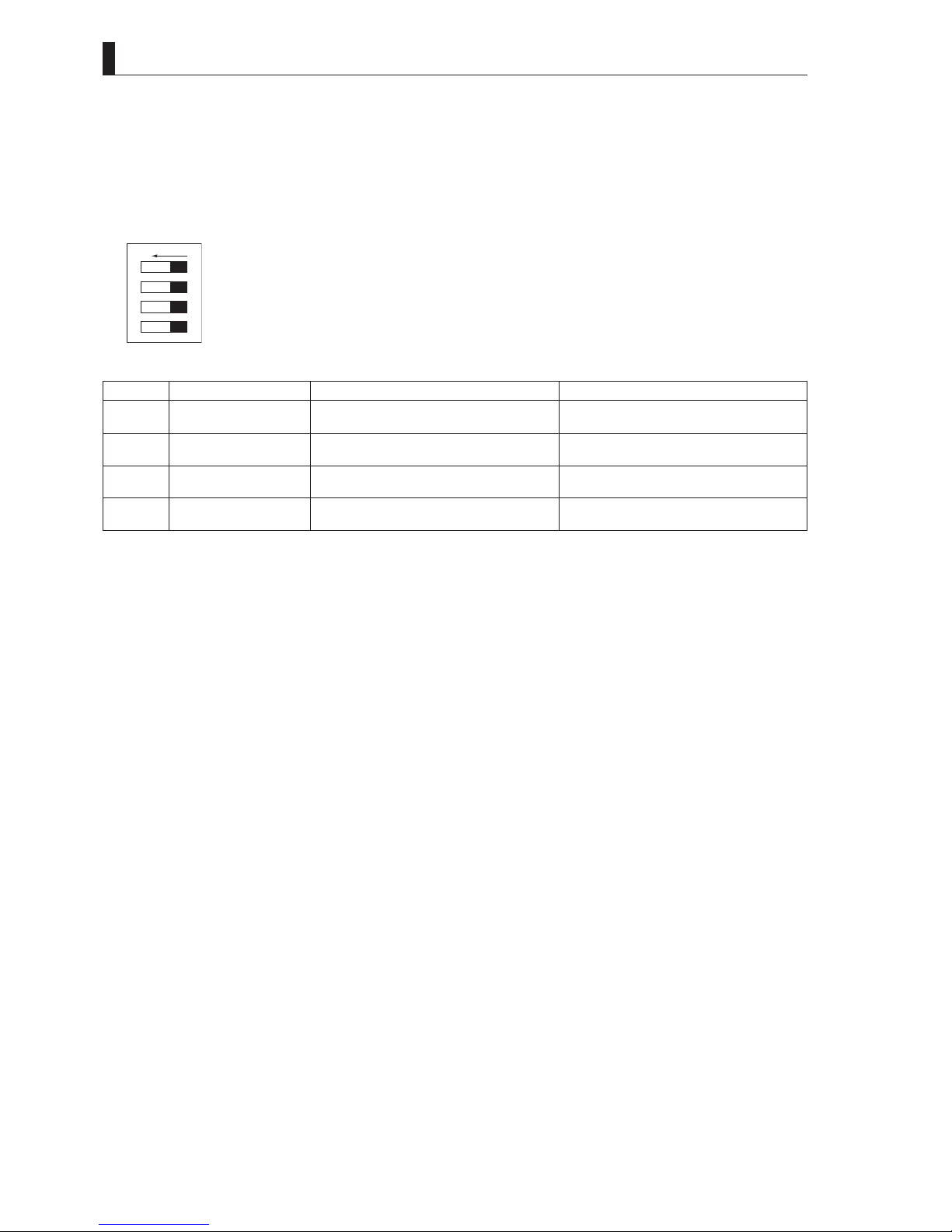
⑮
Setting switches for the intercom system
ON
1
2
3
4
(Switches viewed from the front of the CCU)
Switch No. Switch Function Name ON OFF
1 ENG RTS/CC When the ENG line of the system is used for
"RTS" or "Clearcom"
When the ENG line of the system is used for
"4W "
2 ENG CC ON When the ENG line of the system is used for
"Clearcom"
When the ENG line of the system is used for
"RTS"
3 PROD RTS/CC When the PROD line of the system is used for
"RTS" or "Clearcom"
When the PROD line of the system is used for
"4W "
4 PROD CC ON When the PROD line of the system is used for
"Clearcom"
When the PROD line of the system is used for
"RTS"
⑯
Always place the position of this switch to the lower side.
⑰
Always place the position of this switch to the lower side.
 Loading...