

Ikea IUD8555DX1, IUD9500WX0, IUD9500WX2, IUD9750WS0, IUD9750WS1 Installation Guide
...
I KEA ®
INSTALLATIONINSTRUCTIONS
UNDERCOUNTERDISHWASHER
PLASTICGIANT TUBMODELS
INSTRUCTIONSD'INSTALLATION
LAVE-VAISSELLEENCASTRE
MODELESA TRESGRANDE CUVE EN PLASTIQUE
TABLEOF CONTENTS
DISHWASHER SAFETY ............................................................... 2
INSTALLATION REQUIREMENTS .............................................. 3
Tools and Parts .......................................................................... 3
Location Requirements .............................................................. 3
Drain Requirements ................................................................... 4
Water Supply Requirements ...................................................... 5
Electrical Requirements ............................................................. 5
INSTALLATION INSTRUCTIONS ................................................ 5
Prepare Cabinet Opening .......................................................... 5
Prepare Cabinet Opening Where There Are No
Existing Utility Hookups ............................................................. 8
Install Moisture Barrier ............................................................ 11
Prepare Dishwasher ................................................................ 11
Install the Door Handle ............................................................ 13
Custom Panel Dimensions ...................................................... 13
Install Custom Panel ............................................................... 13
Choose Attachment Option .................................................... 14
Move Dishwasher to Final Location ........................................ 16
Level the Dishwasher .............................................................. 16
Make Electrical Connection .................................................... 17
Connect to Water Supply ........................................................ 18
Connect to Drain ..................................................................... 18
Secure Dishwasher inCabinet Opening ................................. 19
Complete Installation .............................................................. 19
TABLEDESMATIERES
SI_CURITI_ DU LAVE-VAISSELLE ............................................ 21
EXIGENCES D'INSTALLATION ................................................ 22
Outils et pieces ........................................................................ 22
Exigences d'emplacement ...................................................... 22
Exigences concernant I'evacuation ........................................ 23
Specifications de I'alimentation en eau .................................. 24
Specifications electriques ....................................................... 24
INSTRUCTIONS D'INSTALLATION .......................................... 24
Amenagement de la cavite d'encastrement du placard ......... 24
Preparation de I'espace d'encastrement
du placard non dote de moyens de raccordement ................ 27
Installation de la barriere anti-humidite ................................... 31
Preparation du lave-vaisselle .................................................. 31
Installation de la poignee de porte .......................................... 33
Dimensions du panneau personnalise .................................... 33
Installation de panneau personnalise ..................................... 34
Choose I'option d'attachement ............................................... 35
Deplacer le lave-vaisselle jusqu'& son emplacement final ..... 36
12tablissement de I'aplomb du lave-vaisselle .......................... 37
Raccordement electrique ........................................................ 37
Raccordement & la canalisation d'eau .................................... 39
Raccordement a I'evacuation ................................................. 39
Fixation du lave-vaisselle dans I'espace d'encastrement ...... 40
Achever I'installation ............................................................... 41
W10254955A
DISHWASHERSAFETY
Your safety and the safety of others are very important.
We have provided many important safety messages in this manual and on your appliance. Always read and obey all safety
messages.
This is the safety alert symbol.
This symbol alerts you to potential hazards that can kill or hurt you and others.
All safety messages will follow the safety alert symbol and either the word "DANGER" or "WARNING."
These words mean:
You can be killed or seriously injured if you don't immediately
follow instructions.
You can be killed or seriously injured if you don'tfollow
instructions.
All safety messages will tell you what the potential hazard is, tell you how to reduce the chance of injury, and tell you what can
happen if the instructions are not followed.
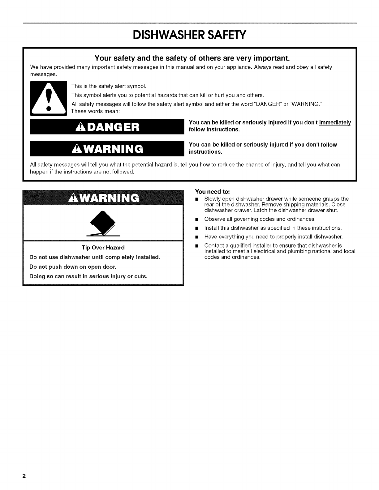
You need to:
• Slowly open dishwasher drawer while someone grasps the
rear of the dishwasher. Remove shipping materials. Close
dishwasher drawer. Latch the dishwasher drawer shut.
• Observe all governing codes and ordinances.
• Install this dishwasher as specified in these instructions.
• Have everything you need to properly install dishwasher.
Tip Over Hazard
Do not use dishwasher until completely installed.
Do not push down on open door.
Doing so can result in serious injury or cuts.
• Contact a qualified installer to ensure that dishwasher is
installed to meet all electrical and plumbing national and local
codes and ordinances.
2
INSTALLATIONREQUIREMENTS
Gather the required tools and parts before starting installation.
Read and follow the instructions provided with any tools listed
here.
Tools needed
• Pliers
• Phillips screwdriver
• Flat-blade screwdriver
• _e" and 1¼,,nut drivers or
hex sockets
• Measuring tape or ruler
• 11/2"hole saw bit
• Twist-on wire connectors
[proper size to connect
household wiring to 16-
gauge wiring in
dishwasher] (2)
• 15 TORX®tscrewdriver
(if installing custom front
panels)
Parts needed
• 90° elbow with 3/8"N.RT.
external threads on one
end. (The other end must
fit your water supply line.)
• Teflon®ttape or pipe joint
compound
Tools needed (new installation)
• Cordless drill •
• 1/2",3/4"and 11/2"hole saw •
bits •
Parts needed (new installation)
• Copper tubing (3/8" •
recommended) or
• Flexible stainless steel
braided fill line
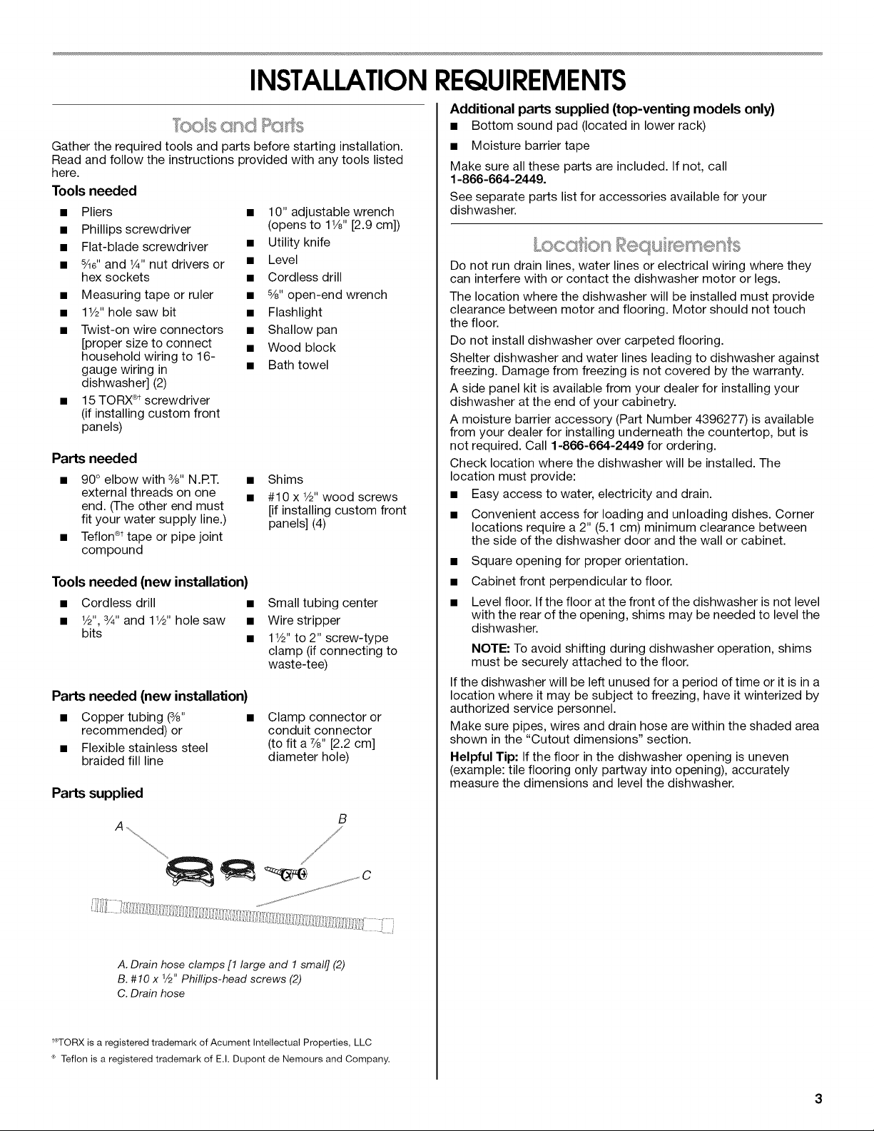
Parts supplied
• 10" adjustable wrench
(opens to 11/8"[2.9 cm])
• Utility knife
• Level
• Cordless drill
• 8/8"open-end wrench
• Flashlight
• Shallow pan
• Wood block
• Bath towel
Shims
#10 x 1/2"wood screws
[if installing custom front
panels] (4)
Small tubing center
Wire stripper
1V2"to 2" screw-type
clamp (if connecting to
waste-tee)
Clamp connector or
conduit connector
(to fit a 7/8"[2.2 cm]
diameter hole)
B
Additional parts supplied (top-venting models only)
• Bottom sound pad (located in lower rack)
• Moisture barrier tape
Make sure all these parts are included. If not, call
1-866-664-2449.
See separate parts list for accessories available for your
dishwasher.
ocoo ec J smen s
Do not run drain lines, water lines or electrical wiring where they
can interfere with or contact the dishwasher motor or legs.
The location where the dishwasher will be installed must provide
clearance between motor and flooring. Motor should not touch
the floor.
Do not install dishwasher over carpeted flooring.
Shelter dishwasher and water lines leading to dishwasher against
freezing. Damage from freezing is not covered by the warranty.
A side panel kit is available from your dealer for installing your
dishwasher at the end of your cabinetry.
A moisture barrier accessory (Part Number 4396277) is available
from your dealer for installing underneath the countertop, but is
not required. Call 1-866-664-2449 for ordering.
Check location where the dishwasher will be installed. The
location must provide:
• Easy access to water, electricity and drain.
• Convenient access for loading and unloading dishes. Corner
locations require a 2" (5.1 cm) minimum clearance between
the side of the dishwasher door and the wall or cabinet.
• Square opening for proper orientation.
• Cabinet front perpendicular to floor.
• Level floor. If the floor at the front of the dishwasher is not level
with the rear of the opening, shims may be needed to level the
dishwasher.
NOTE: To avoid shifting during dishwasher operation, shims
must be securely attached to the floor.
If the dishwasher will be left unused for a period of time or it is in a
location where it may be subject to freezing, have it winterized by
authorized service personnel.
Make sure pipes, wires and drain hose are within the shaded area
shown in the "Cutout dimensions" section.
Helpful Tip: If the floor in the dishwasher opening is uneven
(example: tile flooring only partway into opening), accurately
measure the dimensions and level the dishwasher.
A. Drain hose clamps [1 large and 1 small] (2)
B. #10 x 1/2"Phillips-head screws (2)
C. Drain hose
_TORX is a registered trademark of Acument Intellectual Properties, LLC
<_Teflon is a registered trademark of E.I. Dupont de Nemours and Company.
Product Dimensions
Installation Clearances
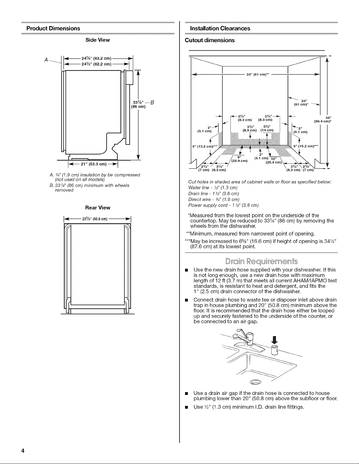
Side View
I_---- 21 " (53.3 cm) -_
A. _" (1.9 cm) insulation by be compressed
(not used on all models)
B. 33 _" (86 cm) minimum with wheels
removed
Rear View
237/8 '' (60.6 cm)
Cutout dimensions
24"
(61 cm)*
34"
(86.4 cm)*
(5.1 cm)
6" (15.2 cm)***
(5.1 cm) l
(25.4 cm
(8.3 cm) (7 cm) _ --
Cut holes in shaded area of cabinet walls or floor as specified below:
Water line - ½" (1.3 cm)
Drain line - 1 ½" (3.8 cm)
Direct wire - _" (1.9 cm)
Power supply cord - 1½" (3.8 cm)
*Measured from the lowest point on the underside of the
countertop. May be reduced to 337/8'' (86 cm) by removing the
wheels from the dishwasher.
**Minimum, measured from narrowest point of opening.
***May be increased to 68/8'' (16.6 cm) if height of opening is 341/2''
(87.6 cm) at its lowest point.
Use the new drain hose supplied with your dishwasher. If this
is not long enough, use a new drain hose with maximum
length of 12 ft (3.7 m) that meets all current AHAM/IAPMO test
standards, is resistant to heat and detergent, and fits the
1" (2.5 cm) drain connector of the dishwasher.
Connect drain hose to waste tee or disposer inlet above drain
trap in house plumbing and 20" (50.8 cm) minimum above the
floor. It is recommended that the drain hose either be looped
up and securely fastened to the underside of the counter, or
be connected to an air gap.
Use a drain air gap if the drain hose is connected to house
plumbing lower than 20" (50.8 cm) above the subfloor or floor.
Use 1/2"(1.3 cm) minimum I.D. drain line fittings.
odp©/y
• A hot water line with 20-120 psi (138-862 kPa) water pressure.
• 120°F (49°C) water temperature at dishwasher.
• Flexible stainless steel braided fill line (1/2" minimum plastic
tubing is not recommended).
Contact a qualified electrician.
Ensure that the electrical installation is adequate and in
conformance with all national and local codes and ordinances.
You must have:
• 120-volt, 60 Hz, AC-only, 15 or 20 amp fused electrical supply.
• Copper wire only.
We recommend:
• A time-delay fuse or circuit breaker.
• A separate circuit.
INSTALLATIONINSTRUCTIONS
If direct wiring dishwasher:
• Use flexible, armored or nonmetallic sheathed, copper wire
with grounding wire that meets the wiring requirements for
your home and local codes and ordinances.
Use strain relief method provided with house wiring junction
box or install a UL-listed/CSA-certified clamp connector to the
house wiring junction box. If using conduit, use a
UL-listed/CSA-certified conduit connector.
If connecting dishwasher with a power supply cord:
• Use Power Supply Cord Kit (Part Number 4317824) marked
for use with dishwashers. Kit contents include:
• Voltex, Inc., UL listed 16 gauge 3 wire power supply cord
with 3 prong grounded plug.
• Neer C-500 _/2'strain relief.
• 3 wire connectors.
• Part Number 302797 grommet.
Follow the kit instructions for installing the power supply cord.
Power supply cord must plug into a mating three prong,
grounded outlet, located in the cabinet next to the dishwasher
opening. Outlet must meet all local codes and ordinances.
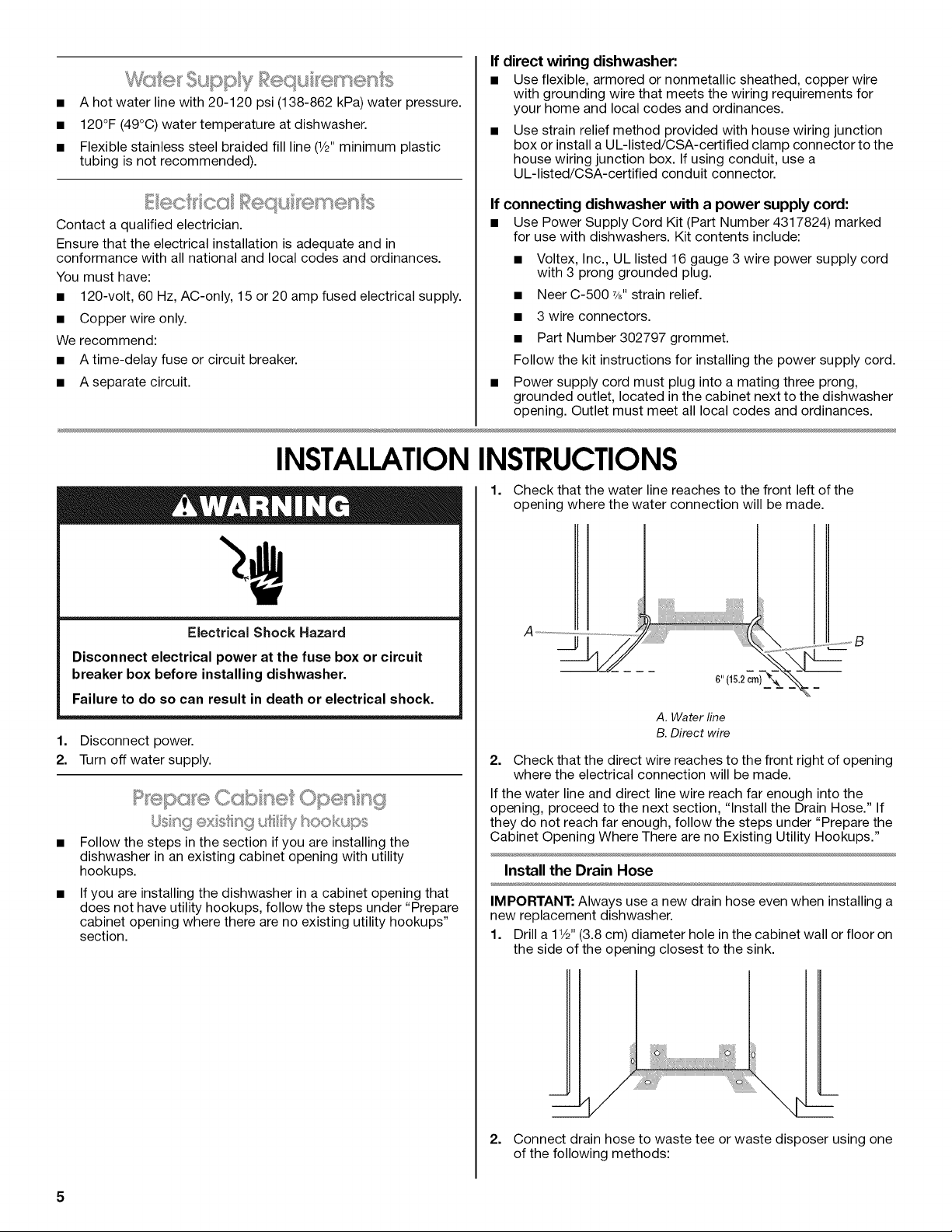
1. Check that the water line reaches to the front left of the
opening where the water connection will be made.
Electrical Shock Hazard
Disconnect electrical power at the fuse box or circuit
breaker box before installing dishwasher.
Failure to do so can result in death or electrical shock.
1. Disconnect power.
2. Turn off water supply.
/,,Jst_9 ®xsn 9 u ty hookups
Follow the steps in the section if you are installing the
dishwasher in an existing cabinet opening with utility
hookups.
If you are installing the dishwasher in a cabinet opening that
does not have utility hookups, follow the steps under "Prepare
cabinet opening where there are no existing utility hookups"
section.
A. Water line
B. Direct wire
2. Check that the direct wire reaches to the front right of opening
where the electrical connection will be made.
If the water line and direct line wire reach far enough into the
opening, proceed to the next section, "Install the Drain Hose." If
they do not reach far enough, follow the steps under "Prepare the
Cabinet Opening Where There are no Existing Utility Hookups."
Install the Drain Hose
IMPORTANT: Always use a new drain hose even when installing a
new replacement dishwasher.
1. Drill a 1V2"(3.8 cm) diameter hole in the cabinet wall or floor on
the side of the opening closest to the sink.
i/ i
2=
Connect drain hose to waste tee or waste disposer using one
of the following methods:
5
• Option 1, Waste disposer- with air gap
• Option 2, No waste disposer- with air gap
• Option 3, Waste disposer- no air gap*
• Option 4, No waste disposer- no air gap*
*An air gap is recommended.
Helpful Tip" To reduce the vibration of the hose, keep the
hose away from the floor and the edge of the hole where it
passes through the cabinet.
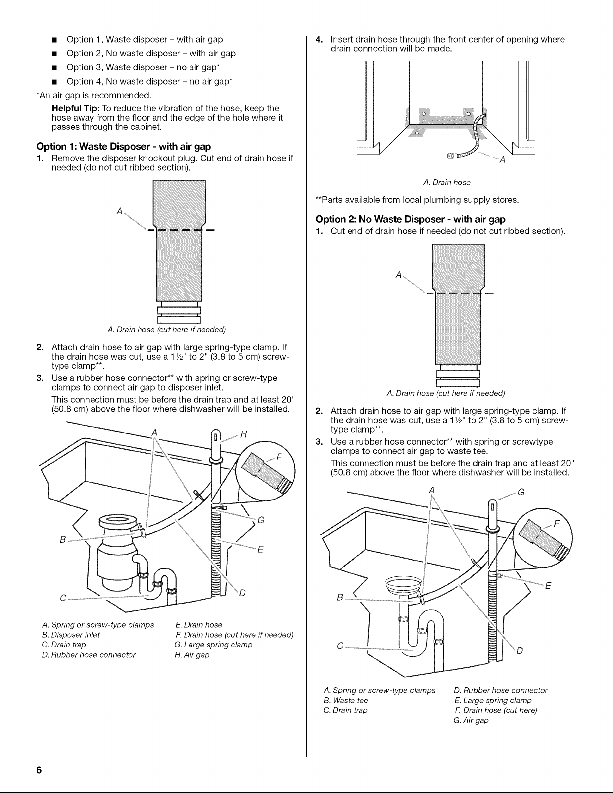
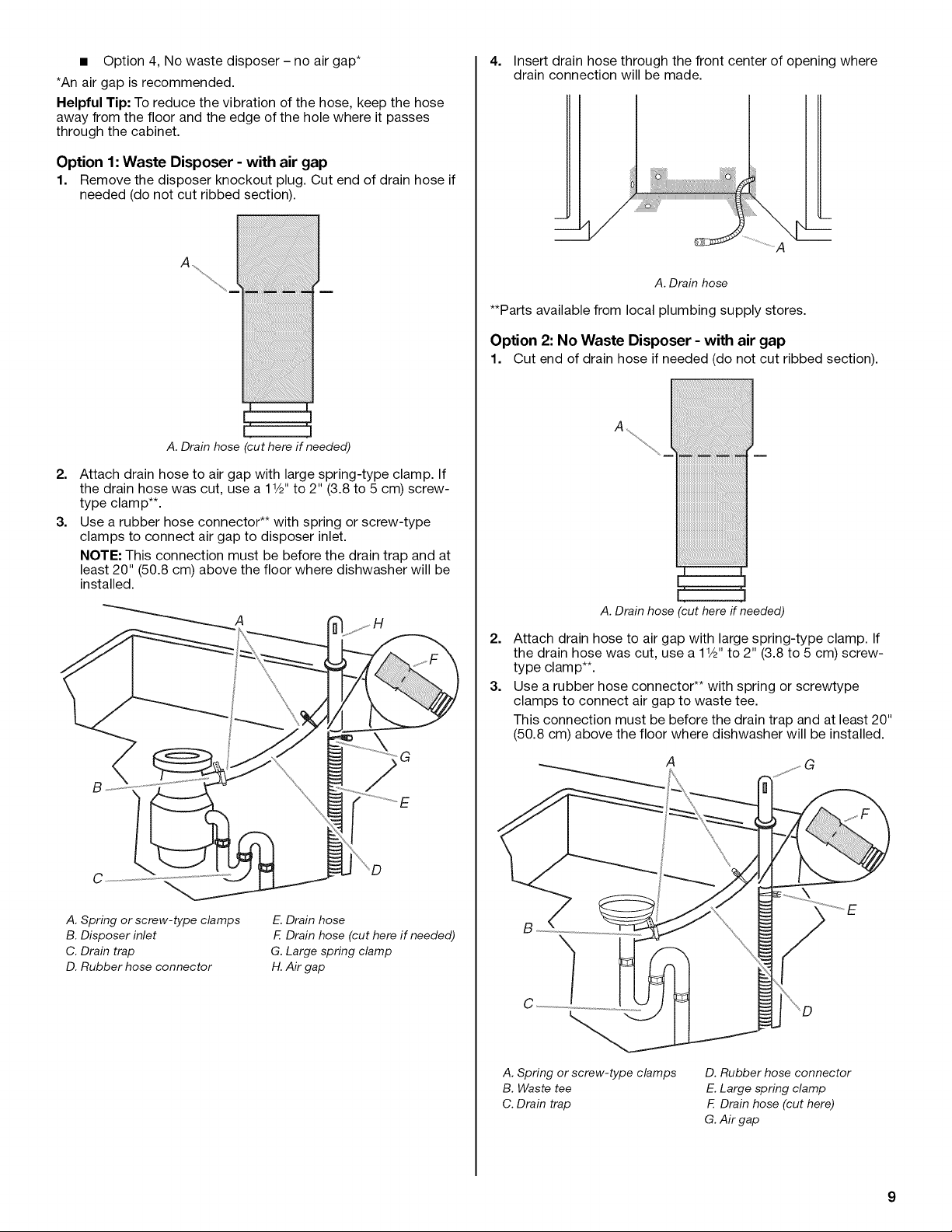
Option 1: Waste Disposer - with air gap
1. Remove the disposer knockout plug. Cut end of drain hose if
needed (do not cut ribbed section).
A.Drain hose cut here if needed)
4. Insert drain hose through the front center of opening where
drain connection will be made.
A
A. Drain hose
**Parts available from local plumbing supply stores.
Option 2: No Waste Disposer - with air gap
1. Cut end of drain hose if needed (do not cut ribbed section).
2. Attach drain hose to air gap with large spring-type clamp. If
the drain hose was cut, use a 1W' to 2" (3.8 to 5 cm) screw-
type clamp**.
3. Use a rubber hose connector** with spring or screw-type
clamps to connect air gap to disposer inlet.
This connection must be before the drain trap and at least 20"
(50.8 cm) above the floor where dishwasher will be installed.
A H
G
C
A. Spring or screw-type clamps
B.Disposer inlet
C. Drain trap
D. Rubber hose connector
E.Drain hose
F. Drain hose (cut here if needed)
G. Large spring clamp
H. Air gap
A. Drain hose (cut here if needed)
2. Attach drain hose to air gap with large spring-type clamp. If
the drain hose was cut, use a 1W' to 2" (3.8 to 5 cm) screw-
type clamp**.
3. Use a rubber hose connector** with spring or screwtype
clamps to connect air gap to waste tee.
This connection must be before the drain trap and at least 20"
(50.8 cm) above the floor where dishwasher will be installed.
A
A. Spring or screw-type clamps
B. Waste tee
C. Drain trap
D. Rubber hose connector
E.Large spring clamp
F. Drain hose (cut here)
G. Air gap
6
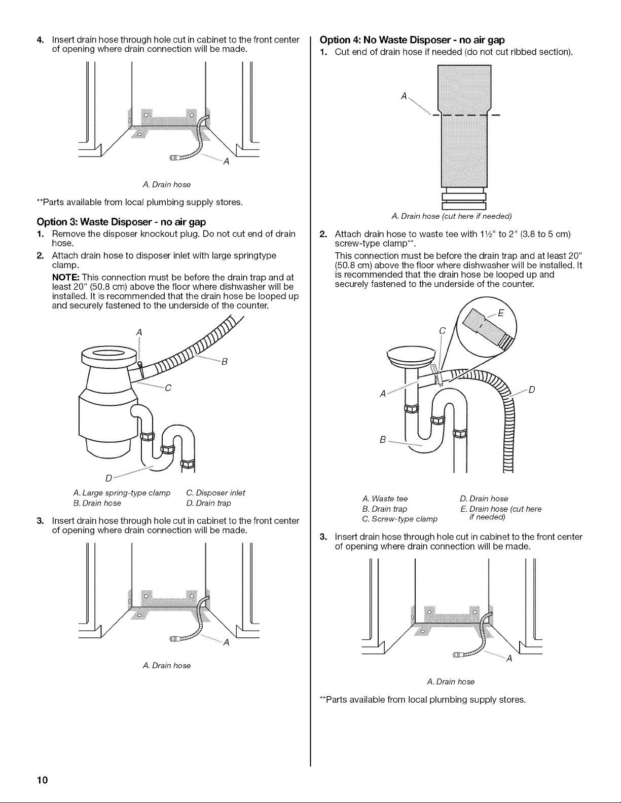
4. Insert drain hose through hole cut in cabinet to the front center
of opening where drain connection will be made.
L
A
Option 4: No Waste Disposer - no air gap
1. Cut end of drain hose if needed (do not cut ribbed section).
A. Drain hose
**Parts available from local plumbing supply stores.
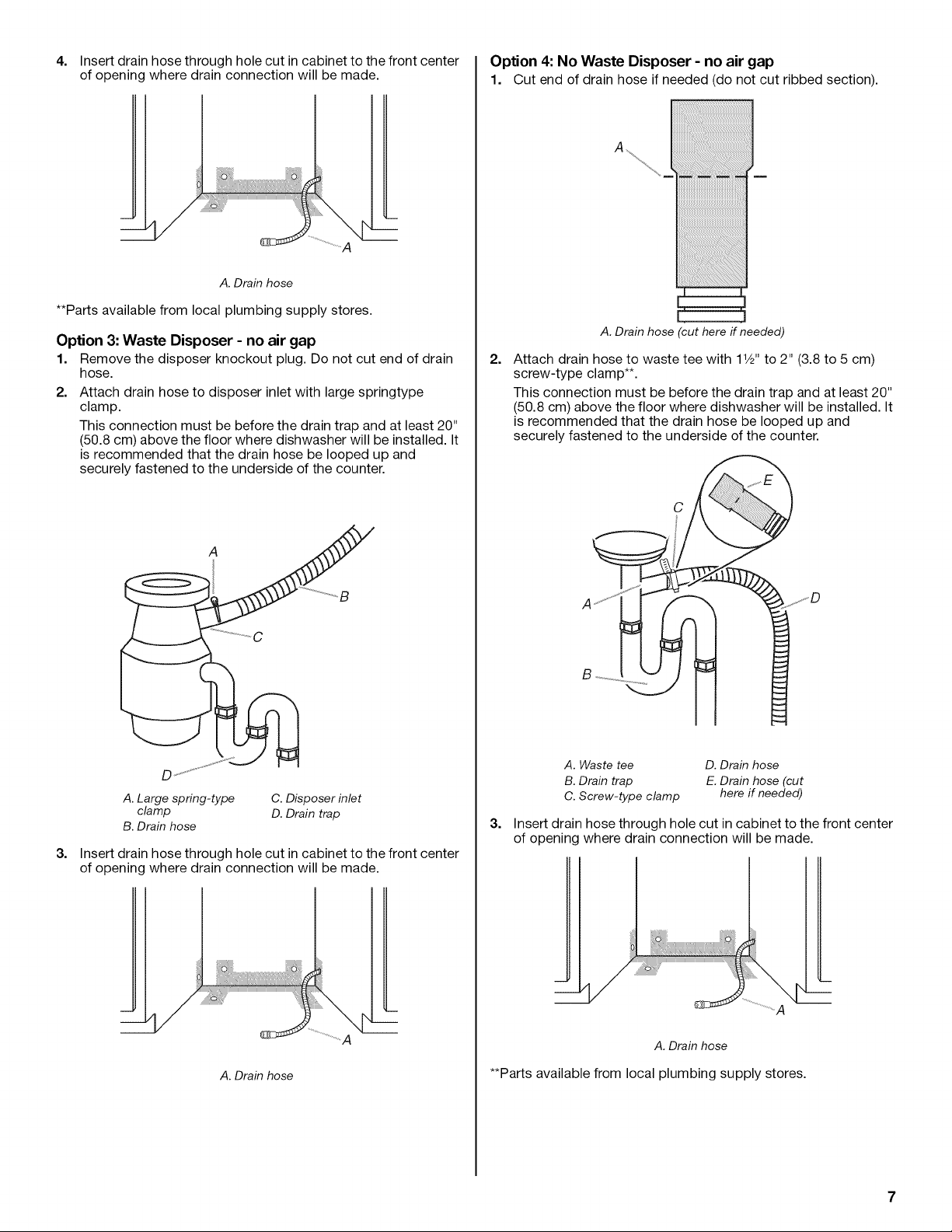
Option 3: Waste Disposer - no air gap
1. Remove the disposer knockout plug. Do not cut end of drain
hose.
2.
Attach drain hose to disposer inlet with large springtype
clamp.
This connection must be before the drain trap and at least 20"
(50.8 cm) above the floor where dishwasher will be installed. It
is recommended that the drain hose be looped up and
securely fastened to the underside of the counter.
I I
A. Drain hose but here if needed)
2.
Attach drain hose to waste tee with 11/2"to 2" (3.8 to 5 cm)
screw-type clamp**.
This connection must be before the drain trap and at least 20"
(50.8 cm) above the floor where dishwasher will be installed. It
is recommended that the drain hose be looped up and
securely fastened to the underside of the counter.
A. Large spring-type C. Disposer inlet
clamp D. Drain trap
B. Drain hose
3.
Insert drain hose through hole cut in cabinet to the front center
of opening where drain connection will be made.
L
A
A. Drain hose
A. Waste tee D. Drain hose
B. Drain trap E.Drain hose (cut
C. Screw-type clamp here if needed)
3.
Insert drain hose through hole cut in cabinet to the front center
of opening where drain connection will be made.
A.Drain hose
**Parts available from local plumbing supply stores.
Electrical Connection
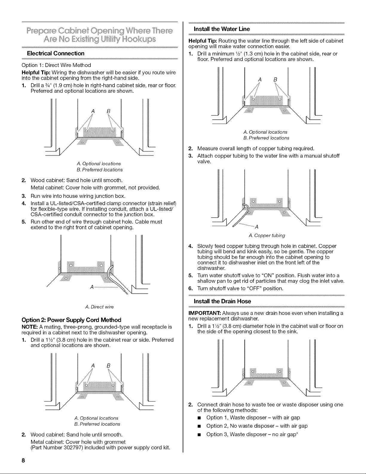
Option 1: Direct Wire Method
Helpful Tip: Wiring the dishwasher will be easier if you route wire
into the cabinet opening from the right-hand side.
1. Drill a 3/4"(1.9 cm) hole in right-hand cabinet side, rear or floor.
Preferred and optional locations are shown.
A B
A. Optional locations
B. Preferred locations
Wood cabinet: Sand hole until smooth.
2.
Metal cabinet: Cover hole with grommet, not provided.
3. Run wire into house wiring junction box.
4. Install a UL-listed/CSA-certified clamp connector (strain relief)
for flexible-type wire. If installing conduit, attach a UL-listed/
CSA-certified conduit connector to the junction box.
5. Run other end of wire through cabinet hole. Cable must
extend to the right front of cabinet opening.
A
Install the Water Line
Helpful Tip: Routing the water line through the left side of cabinet
opening will make water connection easier.
1. Drill a minimum 1/2"(1.3 cm) hole in the cabinet side, rear or
floor. Preferred and optional locations are shown.
A B
A. Optional locations
B. Preferred locations
2. Measure overall length of copper tubing required.
3. Attach copper tubing to the water line with a manual shutoff
valve.
A. Copper tubing
4.
Slowly feed copper tubing through hole in cabinet. Copper
tubing will bend and kink easily, so be gentle. The copper
tubing should be far enough into the cabinet opening to
connect it to dishwasher inlet on the front left of the
dishwasher.
5. Turn water shutoff valve to "ON" position. Flush water into a
shallow pan to get rid of particles that may clog the inlet valve.
6. Turn shutoff valve to "OFF" position.
A. Direct wire
Option 2: Power Supply Cord Method
NOTE: A mating, three-prong, grounded-type wall receptacle is
required in a cabinet next to the dishwasher opening.
1. Drill a 1V2"(3.8 cm) hole in the cabinet rear or side. Preferred
and optional locations are shown.
A B
A. Optional locations
B. Preferred locations
2.
Wood cabinet: Sand hole until smooth.
Metal cabinet: Cover hole with grommet
(Part Number 302797) included with power supply cord kit.
8
Install the Drain Hose
IMPORTANT: Always use a new drain hose even when installing a
new replacement dishwasher.
1. Drill a 11/2"(3.8 cm) diameter hole in the cabinet wall or floor on
the side of the opening closest to the sink.
2.
Connect drain hose to waste tee or waste disposer using one
of the following methods:
• Option 1, Waste disposer- with air gap
• Option 2, No waste disposer- with air gap
• Option 3, Waste disposer- no air gap*
• Option 4, No waste disposer- no air gap*
*An air gap is recommended.
Helpful Tip: To reduce the vibration of the hose, keep the hose
away from the floor and the edge of the hole where it passes
through the cabinet.
Option 1: Waste Disposer - with air gap
1. Remove the disposer knockout plug. Cut end of drain hose if
needed (do not cut ribbed section).
A.Drain hose cut here if needed)
2=
Attach drain hose to air gap with large spring-type clamp. If
the drain hose was cut, use a 1V2"to 2" (3.8 to 5 cm) screw-
type clamp**.
3=
Use a rubber hose connector** with spring or screw-type
clamps to connect air gap to disposer inlet.
NOTE: This connection must be before the drain trap and at
least 20" (50.8 cm) above the floor where dishwasher will be
installed.
4. Insert drain hose through the front center of opening where
drain connection will be made.
A
A. Drain hose
**Parts available from local plumbing supply stores.
Option 2: No Waste Disposer - with air gap
1. Cut end of drain hose if needed (do not cut ribbed section).
C
A. Spring or screw-type clamps
B. Disposer inlet
C. Drain trap
D. Rubber hose connector
A H
E.Drain hose
F. Drain hose (cut here if needed)
G. Large spring clamp
H. Air gap
A. Drain hose (cut here if needed)
2. Attach drain hose to air gap with large spring-type clamp. If
the drain hose was cut, use a 1V2"to 2" (3.8 to 5 cm) screw-
type clamp**.
3. Use a rubber hose connector** with spring or screwtype
clamps to connect air gap to waste tee.
This connection must be before the drain trap and at least 20"
(50.8 cm) above the floor where dishwasher will be installed.
G
A
A. Spring or screw-type clamps
B. Waste tee
C. Drain trap
D. Rubber hose connector
E.Large spring clamp
F. Drain hose (cut here)
G. Air gap
4. Insert drain hose through hole cut in cabinet to the front center
of opening where drain connection will be made.
L
A
Option 4: No Waste Disposer - no air gap
1. Cut end of drain hose if needed (do not cut ribbed section).
A. Drain hose
**Parts available from local plumbing supply stores.
Option 3: Waste Disposer - no air gap
1. Remove the disposer knockout plug. Do not cut end of drain
hose.
2.
Attach drain hose to disposer inlet with large springtype
clamp.
NOTE: This connection must be before the drain trap and at
least 20" (50.8 cm) above the floor where dishwasher will be
installed. It is recommended that the drain hose be looped up
and securely fastened to the underside of the counter.
A
C ................................B
I I
A. Drain hose but here if needed)
2.
Attach drain hose to waste tee with 11/2"to 2" (3.8 to 5 cm)
screw-type clamp**.
This connection must be before the drain trap and at least 20"
(50.8 cm) above the floor where dishwasher will be installed. It
is recommended that the drain hose be looped up and
securely fastened to the underside of the counter.
A. Large spring-type clamp C. Disposer inlet
B. Drain hose D. Drain trap
3. Insert drain hose through hole cut in cabinet to the front center
of opening where drain connection will be made.
L
A
A. Drain hose
10
A. Waste tee D. Drain hose
B. Drain trap E.Drain hose (cut here
C. Screw-type clamp if needed)
3.
Insert drain hose through hole cut in cabinet to the front center
of opening where drain connection will be made.
A. Drain hose
**Parts available from local plumbing supply stores.
'_._ ' s_. _ _ _ ,, _ _
(on some modes}
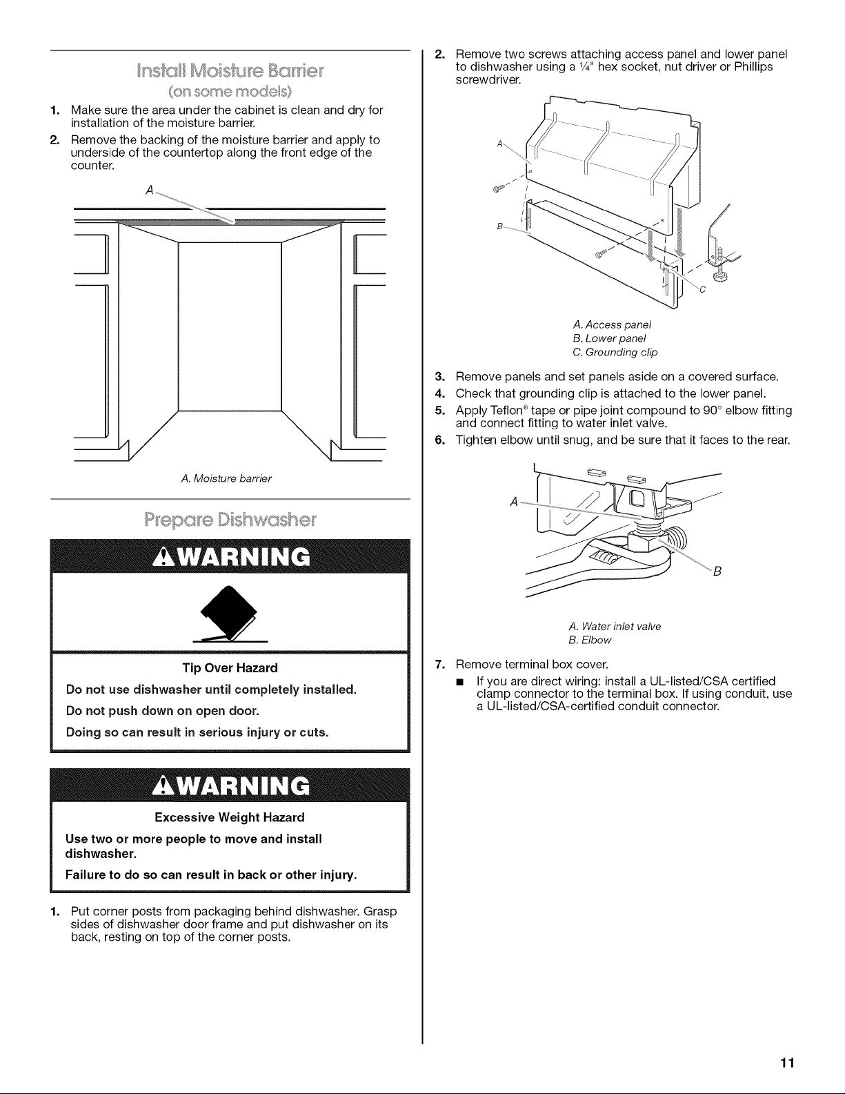
1=
Make sure the area under the cabinet is clean and dry for
installation of the moisture barrier.
2.
Remove the backing of the moisture barrier and apply to
underside of the countertop along the front edge of the
counter.
--¢/ \__
2=
Remove two screws attaching access panel and lower panel
to dishwasher using a V4" hex socket, nut driver or Phillips
screwdriver.
A. Access panel
B. Lower panel
C. Grounding clip
3. Remove panels and set panels aside on a covered surface.
4. Check that grounding clip is attached to the lower panel.
5. Apply Teflon®tape or pipe joint compound to 90° elbow fitting
and connect fitting to water inlet valve.
6. Tighten elbow until snug, and be sure that it faces to the rear.
A. Moisture barrier
!
Tip Over Hazard
Do not use dishwasher until completely installed.
Do not push down on open door.
Doing so can result in serious injury or cuts.
Excessive Weight Hazard
Use two or more people to move and install
dishwasher.
Failure to do so can result in back or other injury.
A. Water inlet valve
B. Elbow
7. Remove terminal box cover.
• If you are direct wiring: install a UL-listed/CSA certified
clamp connector to the terminal box. If using conduit, use
a UL-listed/CSA-certified conduit connector.
1=
Put corner posts from packaging behind dishwasher. Grasp
sides of dishwasher door frame and put dishwasher on its
back, resting on top of the corner posts.
11
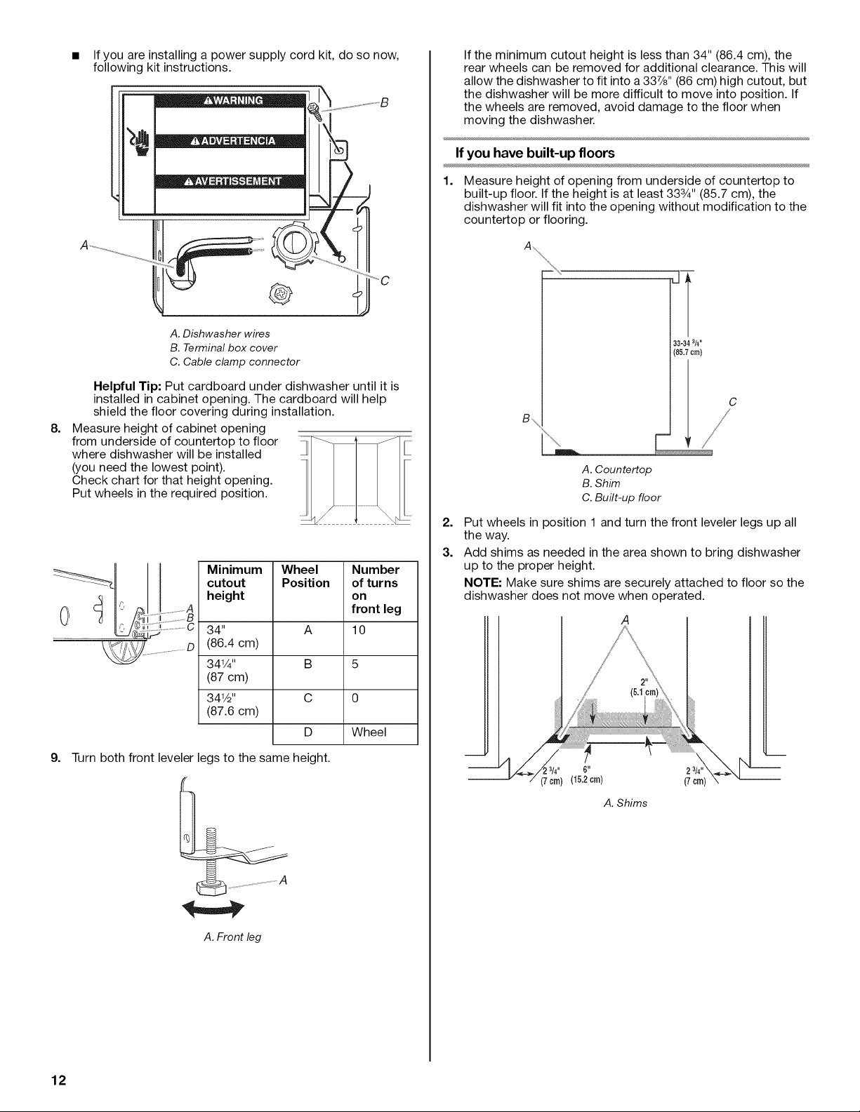
If you are installing a power supply cord kit, do so now,
following kit instructions.
B
If the minimum cutout height is less than 34" (86.4 cm), the
rear wheels can be removed for additional clearance. This will
allow the dishwasher to fit into a 337/8'' (86 cm) high cutout, but
the dishwasher will be more difficult to move into position. If
the wheels are removed, avoid damage to the floor when
moving the dishwasher.
w
A. Dishwasher wires
B. Terminal box cover
C. Cable clamp connector
Helpful Tip: Put cardboard under dishwasher until it is
installed in cabinet opening. The cardboard will help
shield the floor covering during installation.
8.
Measure height of cabinet opening
from underside of countertop to floor
where dishwasher will be installed
(you need the lowest point).
Check chart for that height opening.
Put wheels in the required position.
Minimum Wheel Number
cutout Position of turns
height on
34" A 10
(86.4 cm)
341/4" B 5
(87 cm)
341/2'' C 0
(87.6 cm)
front leg
D Wheel
If you have built-up floors
1=
Measure height of opening from underside of countertop to
built-up floor. If the height is at least 333/4'' (85.7 cm), the
dishwasher will fit into the opening without modification to the
countertop or flooring.
33-343/4"
(85.7cm)
A. Countertop
B. Shim
C. Built-up floor
2.
Put wheels in position 1 and turn the front leveler legs up all
the way.
3.
Add shims as needed in the area shown to bring dishwasher
up to the proper height.
NOTE: Make sure shims are securely attached to floor so the
dishwasher does not move when operated.
g.
Turn both front leveler legs to the same height.
A. Front leg
12
3/4" 6"
\
(7 crn)(15.2 cm) (7 crn)
A. Shims
Custom door panel dimensions
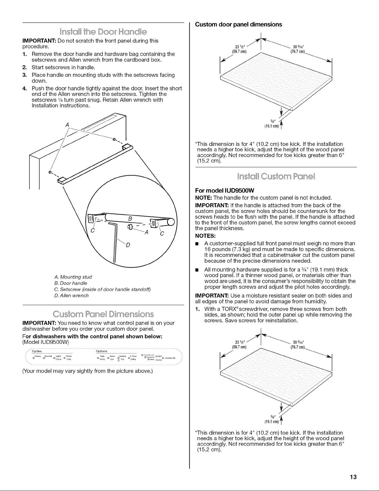
IMPORTANT: Do not scratch the front panel during this
procedure.
1. Remove the door handle and hardware bag containing the
setscrews and Allen wrench from the cardboard box.
2. Start setscrews in handle.
3. Place handle on mounting studs with the setscrews facing
down.
4=
Push the door handle tightly against the door. Insert the short
end of the Allen wrench into the setscrews. Tighten the
setscrews 1/4turn past snug. Retain Allen wrench with
Installation Instructions.
A
A. Mounting stud
B.Door handle
C. Setscrew (inside of door handle standoff)
D. Allen wrench
IMPORTANT: You need to know what control panel is on your
dishwasher before you order your custom door panel.
For dishwashers with the control panel shown below:
(Model IUD9500W)
/" Cycles Options
@_w @No_m_@C_I_U_U@_ @....H4g_ @_t_ _at_D_y @4H°_D_I_y@'_@_dLoo_@_ _,_o,@TAmaA_C_L@
(59.7crn)
30 3/16"
*This dimension is for 4" (10.2 cm) toe kick. If the installation
needs a higher toe kick, adjust the height of the wood panel
accordingly. Not recommended for toe kicks greater than 6"
(15.2 cm).
..... ,,.,.,_,_;::_0__ _ _,_.............
For model IUD9500W
NOTE: The handle for the custom panel is not included.
IMPORTANT: If the handle is attached from the back of the
custom panel, the screw holes should be countersunk for the
screws heads to be flush with the panel. If the handle is attached
to the front of the custom panel, the screw lengths cannot exceed
the panel thickness.
NOTES:
A customer-supplied full front panel must weigh no more than
16 pounds (7.3 kg) and must be made to specific dimensions.
It is recommended that a cabinetmaker cut the custom panel
because of the precise dimensions needed.
All mounting hardware supplied is for a 3/4"(19.1 mm) thick
wood panel. If a thinner wood panel, or materials other than
wood are used, it is the consumer's responsibility to obtain the
proper length screws and adjust the pilot holes accordingly.
IMPORTANT: Use a moisture resistant sealer on both sides and
all edges of the panel to avoid damage from humidity.
1. With a TORX@screwdriver, remove three screws from both
sides, as shown; hold the outer panel up while removing the
screws. Save screws for reinstallation.
(Your model may vary sightly from the picture above.)
*This dimension is for 4" (10.2 cm) toe kick. If the installation
needs a higher toe kick, adjust the height of the wood panel
accordingly. Not recommended for toe kicks greater than 6"
(15.2 cm).
13
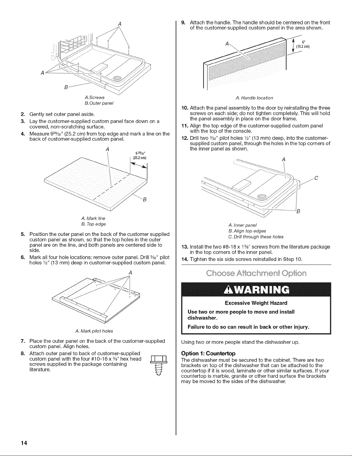
A
9. Attach the handle. The handle should be centered on the front
of the customer-supplied custom panel in the area shown.
!
-.j
A
B
A.Screws
B.Outer panel
2. Gently set outer panel aside.
3. Lay the customer-supplied custom panel face down on a
covered, non-scratching surface.
4. Measure 92%2" (25.2 cm) from top edge and mark a line on the
back of customer-supplied custom panel.
A
A. Mark line
B. Top edge
5=
Position the outer panel on the back of the customer supplied
9 29/32"
(25.2crn)
custom panel as shown, so that the top holes in the outer
panel are on the line, and both panels are centered side to
side.
6=
Mark all four hole locations; remove outer panel. Drill 3/32"pilot
holes 1/2"(13 mm) deep in customer-supplied custom panel.
A
A. Handle location
10. Attach the panel assembly to the door by reinstalling the three
screws on each side; do not tighten completely. This will hold
the panel assembly in place on the door frame.
11. Align the top edge of the customer-supplied custom panel
with the top of the console.
12. Drill two 3/32"pilot holes 1/2"(13 mm) deep, into the customer-
supplied custom panel, through the holes in the top corners of
the inner panel as shown.
A. Inner panel
B. Align top edges
C. Drill through these holes
13. Install the two #8-1 8 x 13/8"screws from the literature package
in the top corners of the inner panel.
14. Tighten the six side screws reinstalled in Step 10.
A. Mark pilot holes
7=
Place the outer panel on the back of the customer-supplied
custom panel. Align holes.
8.
Attach outer panel to back of customer-supplied
custom panel with the four #10-16 x 3/8"hex head
screws supplied in the package containing
literature.
14
Y
Excessive Weight Hazard
Use two or more people to move and install
dishwasher.
Failure to do so can result in back or other injury.
Using two or more people stand the dishwasher up.
Option 1: Countertop
The dishwasher must be secured to the cabinet. There are two
brackets on top of the dishwasher that can be attached to the
countertop if it is wood, laminate or other similar surfaces. If your
countertop is marble, granite or other hard surface the brackets
may be moved to the sides of the dishwasher.
 Loading...