

Ikea IRS335SDHM00 Owner’s Manual

REFRIGERATOR USER INSTRUCTIONS
THANK YOU for pur
.whirlpool.com
www
visit
You will need your model and serial number
This limited warranty is valid for ve years from the date of purchase, when this major appliance is operated and maintained according
to the instructions attached to or furnished with the product, unless the appliance is named LAGAN in which case this limited warranty
is valid for one year from the date of purchase. This limited warranty is valid only in the United States or Canada and applies only when
the major appliance is used in the country in which it was purchased. Proof of original purchase date is required to obtain service
under this limited warranty.
For warranty concerns, do not take the appliance back to the store. Please contact us in the U.S.A. and Canada at
1-866-664-2449. For additional details on the warranty, see the “W
chasing this high-quality pr
for additional information. If you still need assistance, call us at 1-866-664-2449.
oduct. If you should experience a problem not covered in TROUBLESHOOTING, please
, located on the inside wall of the refrigerator compartment.
Limited Warranty
arranty” section of this manual.
TABLE OF CONTENTS/ CONTENU/ CONTENIDO
REFRIGERA
INSTALLATION INSTRUCTIONS..................3
REFRIGERATOR USE.................................10
REFRIGERATOR FEATURES......................15
FREEZER FEATURES.................................16
DOOR FEATURES.......................................16
REFRIGERATOR CARE..............................17
TROUBLESHOOTING.................................19
ACCESSORIES...........................................23
PERFORMANCE DATA SHEET..................24
WARRANTY
TOR SAFETY
.................................................26
.............................1
SEGURIDAD DEL REFRIGERADOR...............28
INSTRUCCIONES DE INSTALACIÓN.............29
USO DEL REFRIGERADOR............................37
CARACTERÍSTICAS DEL
REFRIGERADOR............................................42
CARACTERÍSTICAS DEL
CONGELADOR................................................43
T
CARACTERÍSTICAS DE LAS PUER
CUIDADO DEL REFRIGERADOR...................44
SOLUCIÓN DE PROBLEMAS.........................47
ACCESORIOS..................................................51
HOJA DE DATOS DE RENDIMIENTO.............52
GARANTÍA.......................................................54
AS.........44
SÉCURITÉ DU RÉFRIGÉRATEUR..........................56
INSTRUCTIONS D’INSTALLATION........................57
UTILISATION DU RÉFRIGÉRATEUR......................65
CARACTÉRISTIQUES DU RÉFRIGÉRATEUR.......70
CARACTÉRISTIQUES DU CONGÉLATEUR..........71
CARACTÉRISTIQUES DE LA PORTE....................72
ENTRETIEN DU RÉFRIGÉRATEUR........................72
DÉPANNAGE...........................................................75
ACCESSOIRES.......................................................79
FICHE DE DONNÉES
RELATIVES AU RENDEMENT................................80
FICHE DE DONNÉES RELATIVES
AU RENDEMENT.....................................................81
GARANTIE..............................................................82
REFRIGERATOR SAFETY
Your safety and the safety of others are very important.
We have provided many important safety messages in this manual and on your appliance. Always read and obey all
safety messages.
This is the safety alert symbol.
This symbol alerts you to potential hazards that can kill or hurt you and others.
All safety messages will follow the safety alert symbol and either the word “DANGER
“WARNING.” These words mean:
You can be killed or seriously injured if you don't
immediately follow instructions.
can be killed or seriously injured if you don't
You
follow instructions.
All safety messages will tell you what the potential hazard is, tell you how to reduce the chance of injury, and tell you
what can
W11105307
happen if the instructions are not followed.
B
” or

IMPORTANT SAFETY INSTRUCTIONS
WARNING:
Plug into a grounded 3 prong outlet.
■
■ Do not remove ground prong.
Do not use an adapter.
■
■
Do not use an extension cord.
Disconnect power before servicing.
■
■
Replace all parts and panels before operating.
Remove doors from your old refrigerator.
■
■
Connect to a potable water supply only.
Use nonflammable cleaner.
■
■
Keep flammable materials and vapors, such as gasoline,
away from refrigerator.
■
Use two or more people to move and install refrigerator.
Do not store explosive substances such as aerosol cans
■
with a flammable propellant in this appliance.
■
If the supply cord is damaged, it must be replaced by
the manufacturer, its service agent or similarly qualified
person in order to avoid a hazard.
To reduce the risk of fire, electric shock, or injury whenusing your refrigerator, followthese basicprecautions:
SAVE THESE INSTRUCTIONS
Disconnect power before installing ice maker (on ice maker
■
kit ready models only).
Use a sturdy glass when dispensing ice (on some models).
■
■
Do not hit the refrigerator glass doors (on some models).
This appliance is not intended for use by persons (including
■
children) with reduced physical, sensory or mental
capabilities, or lack of experience and knowledge, unless
they have been given supervision or instruction concerning
use of the appliance by a person responsible for their
safety.
■
Children should be supervised to ensure that they do not
play with the appliance.
■ This appliance is intended to be used in household and
similar applications such as
– Staff kitchen areas in shops, offices and other working
environments;
– Farm houses and by clients in hotels, motels and other
residential type environments;
– Bed and breakfast type environments;
– Catering and similar non-retail applications.
State of California Proposition 65 Warnings:
WARNING: This product contains one or more chemicals known to the State of California to cause cancer.
WARNING: This product contains one or more chemicals known to the State of California to cause birth defects or other
reproductive harm.
2

Proper Disposal of Your
Old Refrigerator
WARNING
Suffocation Hazard
Remove doors from your old refrigerator.
Failure to do so can result in death or brain damage.
IMPOR
problems of the past. Junked or abandoned refrigerators are
still dangerous, even if they will sit for “just a few days.” If
you are getting rid of your old refrigerator, please follow these
instructions to help prevent accidents.
Before You Throw Away Your Old Refrigerator or Freezer:
TANT: Child entrapment and suffocation are not
ake off the doors.
■ T
■ Leave the shelves in place so that childr
climb inside.
en may not easily
INSTALLATION INSTRUCTIONS
Unpack the Refrigerator
WARNING
Excessive Weight Hazard
Use two or more people to move and install
refrigerator.
Failure to do so can result in back or other injury.
Important information to know about disposal of
refrigerants:
Dispose of refrigerator in accordance with Federal and Local
regulations. Refrigerants must be evacuated by a licensed,
EPA certified refrigerant technician in accordance with
established procedures.
When Moving Your Refrigerator:
Your refrigerator is heavy. When moving the refrigerator for
cleaning or service, be sure to cover the oor with
cardboard or hardboard to avoid oor damage. Always pull
the refrigerator straight out when moving it. Do not wiggle or
“walk” the refrigerator when trying to move it, as oor
damage could occur.
Remove the Packaging
■
Remove tape and glue r
on the refrigerator. Rub a small amount of liquid dish soap
over the adhesive with your ngers. Wipe with warm water
and dry.
Do not use sharp instruments, rubbing alcohol, ammable
■
uids, or abrasive cleaners to r
products can damage the surface of your refrigerator. For
more information see the “Refrigerator Safety” section.
esidue from surfaces before turning
emove tape or glue. These
Clean Befor
■
After you r
inside of your refrigerator before using it. See the cleaning
instructions in the “Refrigerator Care” section.
Important information to know about glass shelves
and covers:
Do not clean glass shelves or covers with warm water when
they are cold. Shelves and covers may break if exposed to
sudden temperature changes or impact, such as bumping.
Tempered glass is designed to shatter into many small,
pebble-size pieces. This is normal. Glass shelves and covers
are heavy. Use both hands when removing them to avoid
dropping.
e Using
emove all of the packaging materials, clean the
3
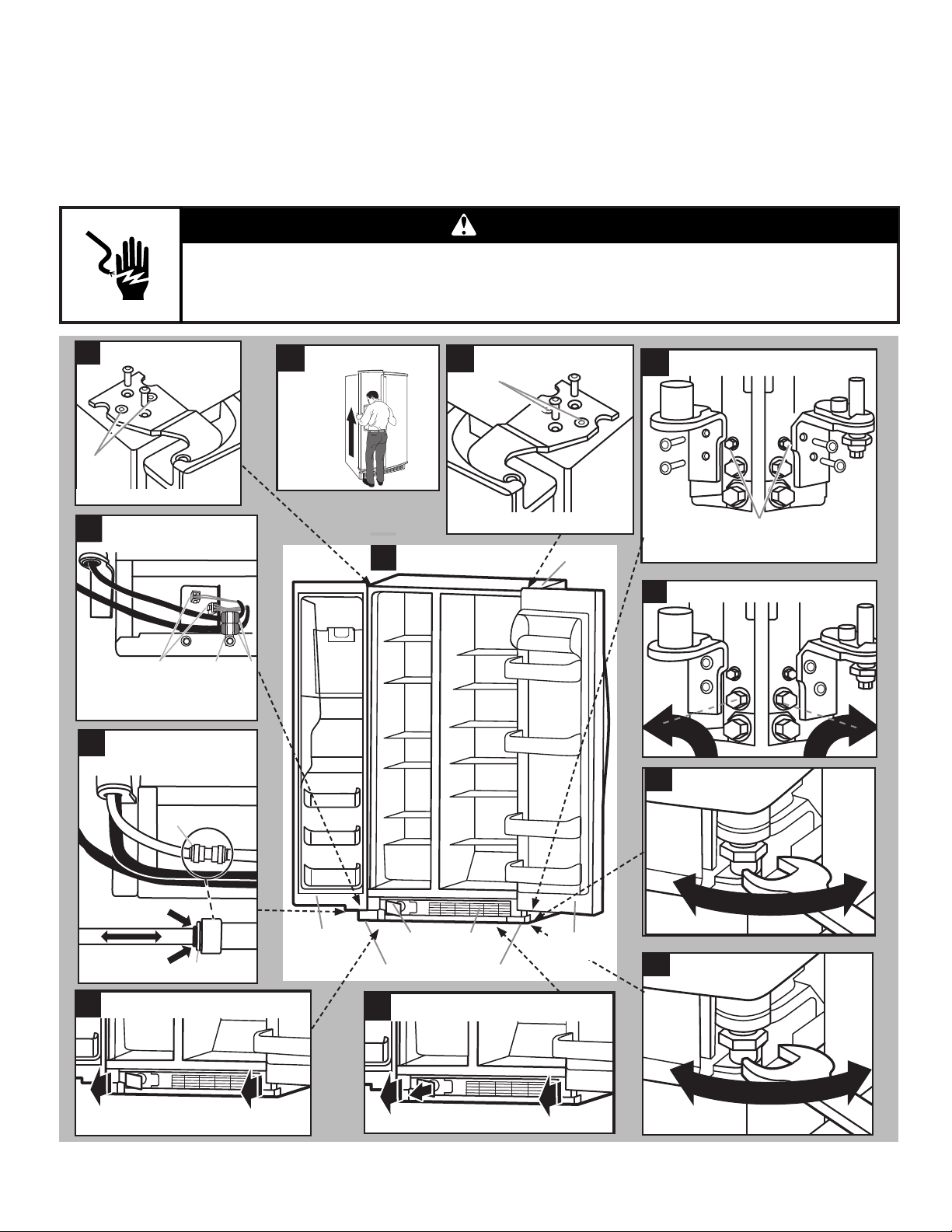
Door Removal, Leveling, and Alignment
Gather the r
NOTE: Before moving your product into your home, measure the doorway of your home to see whether you need to remove the
refrigerator and freezer doors. If door removal is necessary, see the instructions below.
IMPORTANT: Before you begin, unplug refrigerator or disconnect power. Remove food, the ice storage bin (on some models), and
any adjustable door or utility bins fr
TOOLS NEEDED: Bubble level; at-blade screwdriver; 5/16" and 11/16" wrench; 1/4", 3/8", and 5/16" hex-head socket wrenches,
TORX T30
equired tools and parts and read all instructions before starting installation. Save these instructions for future reference.
om doors.
†
scr
ewdriver.
WARNING
Electrical Shock Hazard
Disconnect power before removing doors.
Failure to do so can result in death or electrical shock.
op Left Hinge
T
6
A
Do not remove A screws.
Wiring
5
Door Removal
7
Full Refrigerator
1
T
op Right Hinge
8
A
Do not remove A screws.
Cabinet
Left and Right Bottom Hinge
9
B
Do not remove B screws.
A. Wiring plugs
B. Wiring clip
C. Grommets
4
A. Face of fitting.
3
A CB
Water Dispenser
T
ubing
Base Grille
Leveling scr
Lower
Raise
Locking Nut
11
A
Freezer
door
A
Water
filter door
Adjustable front wheels
Water Filter Door and
2
Base Grille
Base
grille
Refrigerator
door
Loosen
Alignment Scr
12
ews
Raise
Lower
11/16"
wrench
Tighten
ew
A. Pull to the right for extraction.
B. Twist and pass underneath door.
†TORX and T30 ar
e trademarks of Acument Intellectual Properties, LLC.
4
Pull toward you.
Lower
Raise
5/16"
wrench

Remove the Doors
If your refrigerator does not t through the doorway or you are
getting rid of your old refrigerator, follow the steps below for door
removal.
12. If your r
doorway, you may remove both bottom hinges. Use a 5/16"
nut driver to remove these. See graphic 9.
IMPORTANT: Do not remove either screw B.
efrigerator without doors does not pass through the
Replacing or Reinstalling Door and Hinges
WARNING
Electrical Shock Hazard
Disconnect power before removing doors.
Failure to do so can result in death or electrical shock.
1. Unplug r
2.
Fully open both doors. See graphic 1.
3.
If your model has water dispensing, please open the water
lter door by pulling it toward you. See graphic 2. It is not
necessary to r
4.
Pull the base grille towar
the center until it dislodges. See graphic 2.
5.
To remove the base grille, twist and pull the right side until this
side passes underneath the refrigerator door. See graphic 3.
Then pull the left side of the base grille for complete removal.
6.
If your model has water dispensing in the door, disconnect the
water dispenser tubing located below the fr
NOTE: Keep the water tubing connector attached to the tube
that runs underneath the freezer. The door cannot be removed
if the connector is still attached to the tube that runs through
the door hinge.
7.
If your model has water dispensing in the door, disconnect the
wiring located below the fr
8.
Close the fr
to r
IMPORTANT: Do not remove either screw A. Hold the door
while hinge is being removed.
9.
Lift the fr
graphic 7. The water dispenser tubing and wiring will remain
attached to the freezer door.
NOTE: This may require two people, one to lift the door and
another to feed the water tubing and wiring into the bottom
hinge pin.
IMPORTANT: Rest the door on its side on a soft, clean
surface, such as a towel, blanket, or piece of cardboard.
This will help to avoid scratching or damaging the door, water
tubing, and wiring.
10.
Close the r
to remove completely top hinge. See graphic 8.
IMPORTANT: Do not remove either screw A. Hold the door
while the hinge is being removed.
Lift the r
11.
See graphic 7.
IMPORTANT: Rest the door on its side on a soft, clean
surface, such as a towel, blanket, or piece of cardboard.
This will help to avoid scratching or damaging the door
efrigerator or disconnect power.
emove the water lter itself.
d you from the sides and then from
eezer door.
■
Pr
ess the blue outer ring against the face of tting and
pull the dispenser tubing free. See graphic 4.
eezer door. See graphic 5.
Remove the wiring clip and the bracket wir
■
1/4" hexagonal head socket wrench.
■
Disconnect the wiring plugs fr
eezer door and use a TORX T30 screwdriver
emove the top hinge completely. See graphic 6.
eezer door straight up off from the bottom hinge. See
efrigerator door and use a TORX T30 screwdriver
efrigerator door straight up off from the bottom hinge.
om the bracket wire.
e using a
If your doors and bottom hinges have been r
follow the next instructions for reinstallation:
1.
Reinstall both bottom hinges using a 5/16" nut driver to
tighten scr
2.
If your model has water dispensing in the door:
IMPORTANT: Hold the door while hinge is being installed.
3.
Close the fr
a TORX T30 screwdriver to tighten the screws. See graphic 8.
IMPORTANT: Provide additional support for the door while
top hinge is being reinstalled. Do not depend on the door
magnets to hold the door to the cabinet.
4.
If your model has water dispensing in the door, connect the
water dispenser tubing. For the connection, push the tubing
into the dispenser tubing until black mark touches the face of
tting. See graphic 4.
5.
Connect the wiring. See graphic 5.
6. Lift the refrigerator door enough to insert the door into the
bottom hinge pin. See graphic 7.
IMPOR
7. Close the refrigerator door to align and reinstall the top hinge.
Use a TORX T30 screwdriver to tighten the screws. See
graphic 6.
IMPORTANT: Provide additional support for the door while
top hinge is being reinstalled. Do not depend on the door
magnets to hold the door to the cabinet.
ews. See graphic 9.
Lift the fr
■
tubing and wiring through the bottom hinge pin.
NOTE: This may require two people, one to lift the door
and the other to feed the water tubing and wiring into the
bottom hinge pin. See graphic 7.
■
Insert the fr
■
Reinstall the wiring clip and the bracket wir
hexagonal head socket wrench.
■
Connect the wiring plugs fr
eezer door enough to feed the water dispenser
eezer door into the bottom hinge pin.
eezer door to align and reinstall the top hinge. Use
om the bracket wire.
TANT: Hold the door while hinge is being installed.
emoved, please
e using a 1/4"
Leveling and Door Closing
Y
our refrigerator has two front adjustable wheels. See graphic 1.
These are used to level the refrigerator under uneven oor
conditions or want the doors to close more easily. Please follow
the instructions below:
Place the refrigerator into its nal location in the kitchen and
1.
open both doors.
2.
Fully open both doors. See graphic 1.
3.
If your model has water dispensing in the door, please open
the water lter door by pulling it toward you. See graphic 2. It
is not necessary to remove the water lter itself.
4.
Pull the base grille towar
the center until it dislodges. See graphic 2.
5.To remove the base grille, twist and pull the right side until this
side passes underneath the refrigerator door. See graphic 3.
Then pull the left side of the base grille for complete removal.
Use a 3/8" nut driver to turn the leveling screws located in
.
d you from the sides and then from
5
both sides of the r
B
uneven oor conditions, you must turn one or both screws to
the right or left several times to raise or lower the refrigerator.
Until the refrigerator is steady, use a bubble level if necessary.
6.
Close both doors and check that they close as easily as
you like. If not, tur
refrigerator by tiling it more to the back until the doors close
as easily as you like.
7.
Check and make sure that the technician sheet is placed in
the base grille cavity before assembling this into the cabinet.
8.
Reinstall the base grille into the cabinet, introducing the left
side rst and then the right side of the base grille. See graphic
3. You may accommodate the water dispenser tubing and
wiring into base grille cavity below the left bottom hinge.
9.
Attach the base grille pushing into the cabinet clips. See
graphic 2.
efrigerator. See graphic 10. Depending on
n both screws to the right to raise the
Door Alignment
The r
efrigerator doors are designed to be slightly misaligned
vertically when the refrigerator is empty. Please follow the next
steps to align the refrigerator doors.
Use an 11/16" open-ended wrench tool to loosen the locking
1.
nut located below the r
Accommodate the wrench tool so that it ts in the space.
2.
Use a 5/16" open-ended wr
screw. See graphic 12. Depending on how the refrigerator
door is misaligned in relation to the freezer door, you must
turn the screw to the right to raise or to the left to lower the
refrigerator door until both doors have been aligned vertically.
3.
Tighten the 11/16" locking nut with the wrench tool.
4.
Attach the base grille if it was dislodged.
efrigerator door. See graphic 11.
ench tool to turn the alignment
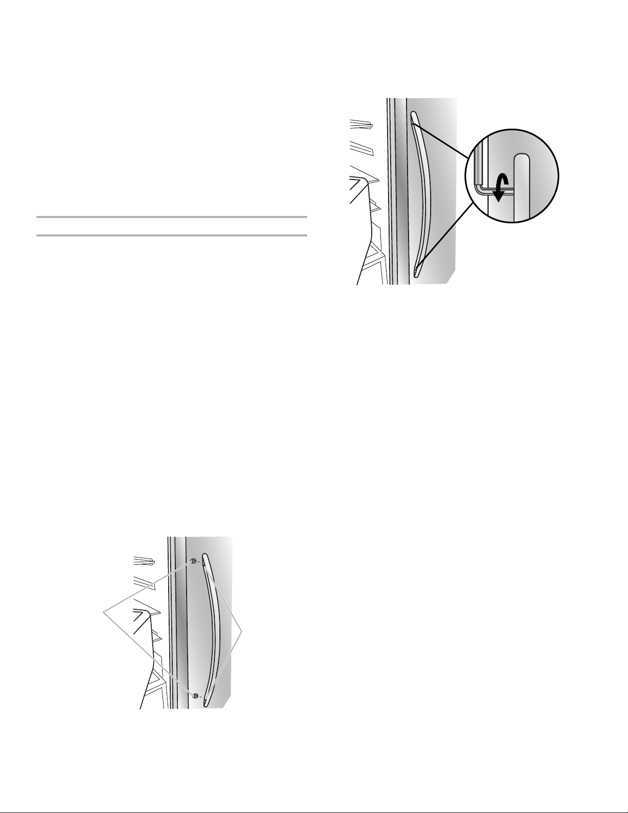
Handle Installation and Removal
ARTS INCLUDED: Door handles (2), 1/8" hex key, spare
P
setscrew(s).
To Install the Handles:
NOTE: The handle mounting setscrews are preinstalled in the
handle.
Remove the handles, which ar
1.
NOTE: To avoid scratching the nish, place the handles on a
towel or other soft surface.
Open the fr
2.
handle on the shoulder screws with the setscrews facing the
freezer.
eezer door. On the refrigerator door, place the
e packed inside the refrigerator.
3. Firmly push the handle toward the door until the handle base
is ush against the door
4.
While holding the handle, insert the short end of the hex key
into the upper hole and slightly rotate the hex key until it is
engaged in the setscr
5. Using a clockwise motion, tighten the setscrew until it begins
to contact the shoulder scr
6.
Repeat steps 4 and 5 to begin fastening the lower setscr
7.
Once both setscrews have been partially tightened as outlined
in the previous steps, fully tighten both the upper and lower
ews.
setscr
IMPORTANT: When the screws feel tight, tighten them an
additional quarter-turn. The handle is not properly installed
without this extra tightening.
8.
Open the r
steps 2 through 7 to install the other handle onto the freezer
door with the setscrews facing the refrigerator.
9.
Save the hex key and all instructions.
o Remove the Handles:
T
1.
While holding the handle, insert the short end of the hex key
into the lower setscr
until it is engaged in the setscrew.
2.
Using a counter
quarterturn at a time.
3.
Repeat steps 1 and 2 for the upper setscr
handle away from the door.
4.
If necessary
screws from the door.
efrigerator door and close the freezer door. Repeat
clockwise motion, loosen the setscrew a
, use a Phillips screwdriver to remove the shoulder
.
ew.
ew.
ew.
ew hole and slightly rotate the hex key
ew. Gently pull the
A
A. Shoulder screws
B. Setscrews inside the handle
6
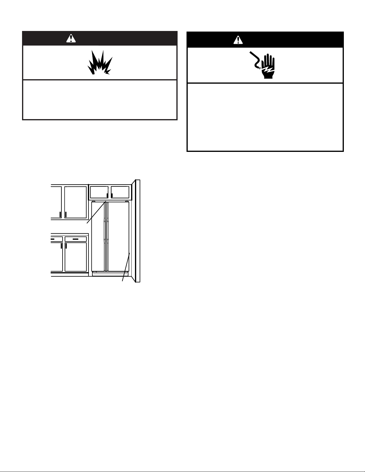
Location Requirements
Electrical Requirements
WARNING
Explosion Hazard
Keep flammable materials and vapors, such as
gasoline, away from refrigerator.
Failure to do so can result in death, explosion, or fire.
IMPOR
use only
To ensure proper ventilation for your refrigerator, allow for
1/2" (12.7 mm) of space on each side and at the top. Allow for
2" (50.8 mm) of space behind the refrigerator. If your refrigerator
has an ice maker, allow extra space at the back for the water line
connections. When installing your refrigerator next to a xed wall,
leave a 2" (50.8 mm) minimum space on each side (depending on
your model) to allow the doors to swing open.
TANT: This refrigerator is designed for indoor household
.
1/2" (12.7 mm)
WARNING
Electrical Shock Hazard
Plug into a grounded 3 prong outlet.
Do not remove ground prong.
Do not use an adapter.
Do not use an extension cord.
Failure to follow these instructions can result in death,
fire, or electrical shock.
Befor
e you move your refrigerator into its nal location, it
is important to make sure you have the proper electrical
connection.
Recommended Grounding Method
A 115 volt, 60 Hz, AC only
electrical supply is required. It is recommended that a separate
circuit serving only your refrigerator be provided. Use an outlet
that cannot be turned off by a switch. Do not use an extension
cord.
NOTE: Befor
or removing a light bulb, disconnect the refrigerator from
the electrical source. When you are nished, reconnect the
refrigerator to the electrical source and reset the control
(Thermostat, Refrigerator, or Freezer Control depending on the
model) to the desired setting. See the “Using the Controls”
section.
e performing any type of installation or cleaning,
, 15 or 20 amp fused, grounded
2" (50.8 mm)
NOTES:
This r
■
efrigerator is intended for use in a location where the
temperature ranges from a minimum of 55°F (13°C) to a
maximum of 110°F (43°C). The preferred room temperature
range for optimum performance, which reduces electricity
usage and provides superior cooling, is between 60°F (15°C)
and 90°F (32°C). It is recommended that you do not install the
refrigerator near a heat source, such as an oven or radiator.
Normal minimum cabinet cut-out width required for product
■
installation is 36" (91.44 cm). However, if the product is placed
against an extended wall and the ability to remove the crisper
pans is desired, an additional 18" (45.72 cm) of cabinet width
is required, so a total cabinet opening width of 54" (137.16
cm) is recommended.
Water Supply Requirements
Gather the r
Read and follow the instructions provided with any tools listed
here.
TOOLS NEEDED:
Flat-blade scr
■
7/16" and 1/2" open-end or
■
two adjustable wr
NOTE: Your refrigerator dealer has a kit available with a
1/4" (6.35 mm) saddle-type shut-off valve, a union, and copper
tubing. Before purchasing, make sure a saddle-type valve
complies with your local plumbing codes. Do not use a piercingtype or 3/16" (4.76 mm) saddle valve which reduces water ow
and clogs more easily.
IMPORTANT:
All installations must meet local plumbing code r
■
■ Use copper tubing and check for leaks. Install copper tubing
only in ar
above freezing.
equired tools and parts before starting installation.
1/4" nut driver
ewdriver
enches
eas where the household temperatures will remain
■
1/4" drill bit
■
dless drill
■ Cor
equirements.
7
Water Pressure
Connect to Water Line
A cold water supply with water pr
essure of between 30 and
120 psi (207 and 827 kPa) is required to operate the
water dispenser and ice maker. If you have questions about
your water pr
■ If your refrigerator has a water dispenser: After installation
essure, call a licensed, qualied plumber.
is complete, use the water dispenser to check the water
pressure.
■ With the water lter removed, dispense 1 cup (237 mL) of
water. If 1 cup of water is dispensed in 8 seconds or less,
the water pressure to the refrigerator meets the minimum
requirement.
If it takes longer than 8 seconds to dispense 1 cup
■
(237 mL) of water
, the water pressure to the refrigerator
is lower than recommended. See the “Troubleshooting”
section for suggestions.
Reverse Osmosis Water Supply
IMPORTANT: The pressure of the water supply coming out of
a reverse osmosis system going to the water inlet valve of the
refrigerator needs to be between 30 and 120 psi (207 and
827 kPa).
If a reverse osmosis water ltration system is connected to your
cold water supply, the water pressure to the reverse osmosis
system needs to be a minimum of 40 to 60 psi (276 to 414 kPa).
If the water pressure to the reverse osmosis system is less than
40 to 60 psi (276 to 414 kPa):
■
Check to see whether the sediment lter in the r
everse
osmosis system is blocked. Replace the lter if necessary.
Allow the storage tank on the r
■
everse osmosis system to rell
after heavy usage.
If your r
■
efrigerator has a water lter, it may further reduce
the water pressure when used in conjunction with a reverse
osmosis system. Remove the water lter. See the “Water
Filtration System” section.
If you have questions about your water pressure, call a licensed,
qualied plumber.
Connect Water Supply
Read all dir
IMPORTANT:
Plumbing shall be installed in accor
■
International Plumbing Code and any local codes and
ordinances.
The gray water tubing on the back of the r
■
is used to connect to the household water line) is a PEX
(crosslinked polyethylene) tube. Copper and PEX tubing
connections from the household water line to the refrigerator
are acceptable, and will help avoid offtaste or odor in your ice
or water. Check for leaks.
Install tubing only in ar
■
above freezing.
TOOLS NEEDED:
Gather the required tools and parts before starting installation.
ections before you begin.
eas where temperatures will remain
Flat-blade scr
■
7/16" and 1/2" open-end wr
■
ewdriver
wrenches
■
1/4" nut driver
dance with the
efrigerator (which
enches or two adjustable
IMPOR
TANT: If you turn the refrigerator on before the water line
is connected, turn the ice maker off.
Style 1 (Recommended)
1.
Unplug r
2.
T
urn off main water supply. Turn on nearest faucet long
efrigerator or disconnect power.
enough to clear line of water.
Use a quarter
3.
-turn shut-off valve or the equivalent, served by
a 1/2" copper household supply line.
NOTE: T
o allow sufcient water ow to the refrigerator,
a minimum 1/2" size copper household supply line is
recommended.
A
B
C
D
A. Bulb
B. Nut
4. Now you ar
e ready to connect the copper tubing to the
C. Copper tubing (to refrigerator)
D. Household supply line (1/2" minimum)
shut-off valve. Use 1/4" (6.35 mm) O.D. (outside diameter)
soft copper tubing to connect the shut-off valve and the
refrigerator.
Ensur
■
e that you have the proper length needed for the job. Be
sure both ends of the copper tubing are cut square.
Slip compr
■
ession sleeve and compression nut onto copper
tubing as shown. Insert end of tubing into outlet end squarely
as far as it will go. Screw compression nut onto outlet end
with adjustable wrench. Do not overtighten.
B CA
A. Compression sleeve
B. Compression nut
5. Place the fr
ee end of the tubing into a container or sink, and
turn on main water supply to
clear. T
urn off shut-off valve on the water pipe.
NOTE:
Always drain the water line befor
C. Copper tubing
ush out tubing until water is
e making the nal
connection to the inlet of the water valve to avoid possible
water valve malfunction.
6.
Bend the copper tubing to meet the water line inlet, which
is located on the back of the r
efrigerator cabinet as shown.
Leave a coil of copper tubing to allow the refrigerator to be
pulled out of the cabinet or away from the wall for service.
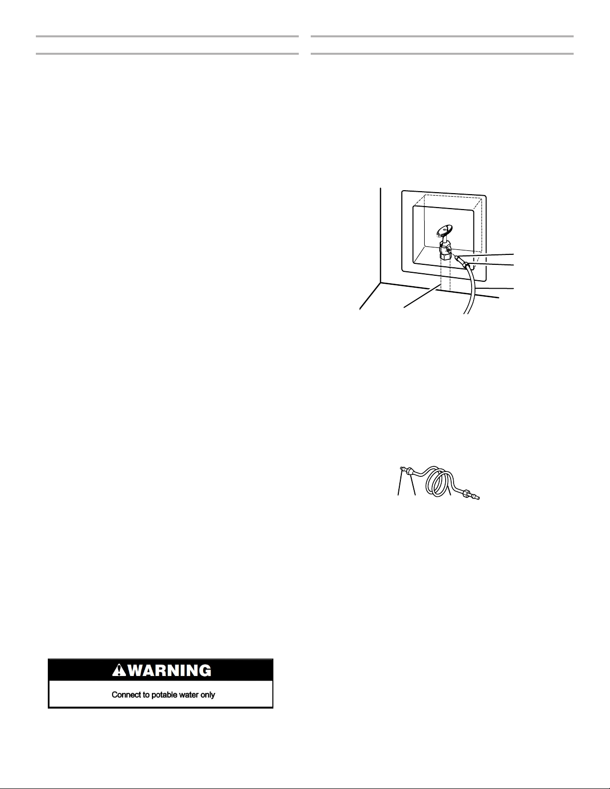
Style 2
1.
Unplug r
2.
T
urn off main water supply. Turn on nearest faucet long
efrigerator or disconnect power.
enough to clear line of water.
3.
Locate a 1/2" (12.7 mm) to 11/4" (3.18 cm) vertical cold water
pipe near the r
efrigerator.
8
IMPORTANT:
■
Make sur
■
Horizontal pipe will work, but drill on the topside of the pipe,
not the bottom. This will help keep water away fr
e it is a cold water pipe.
om the drill
and normal sediment from collecting in the valve.
4.
Determine the length of copper tubing you need. Measure
om the connection on the lower rear corner of refrigerator to
fr
the water pipe. Add 7 ft (2.1 m) to allow for cleaning. Use
1/4" (6.35 mm) O.D. (outside diameter) copper tubing. Be sure
both ends of copper tubing are cut square.
5.
Using a cordless drill, drill a 1/4" (6.35 mm) hole in the cold
water pipe you have selected.
A
G
A. Cold water pipe
B. Pipe clamp
C. Copper tubing
D. Compression nut
B
C
DEF
E. Compression
sleeve
F. Shut-off valve
G. Packing nut
6. Fasten the shut-off valve to the cold water pipe with the pipe
clamp. Be sur
e the outlet end is solidly in the 1/4" (6.35 mm)
drilled hole in the water pipe and that the washer is under the
pipe clamp. Tighten the packing nut. Tighten the pipe clamp
screws slowly and evenly so the washer makes a watertight
seal. Do not overtighten, or you may crush the copper tubing.
7.
Slip the compr
ession sleeve and compression nut on
the copper tubing as shown. Insert the end of the tubing
into the outlet end squarely as far as it will go. Screw the
compression nut onto outlet end with adjustable wrench. Do
not overtighten.
8.
the free end of the tubing in a container or sink, and turn
Place
on the main water supply. Flush the tubing until water is clear.
Turn off the shut-off valve on the water pipe. Coil the copper
tubing.
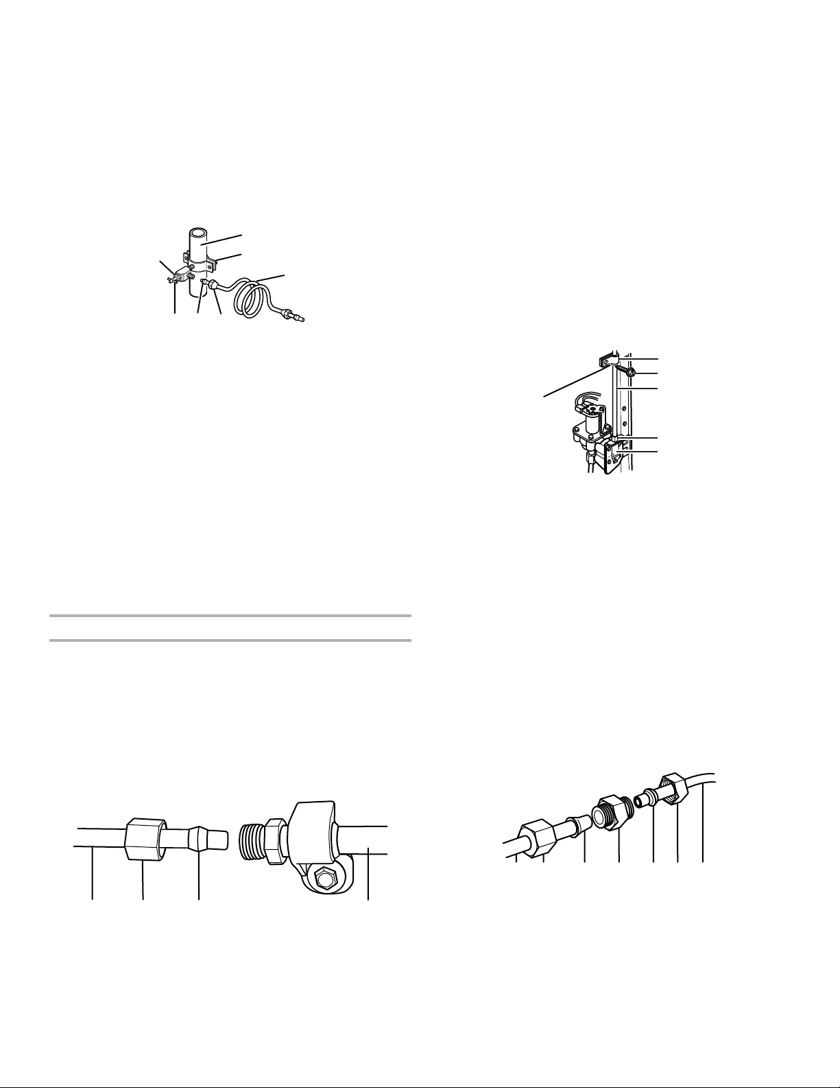
Connect to Refrigerator
Style 1
1.
Unplug r
2.
Remove and discar
of the water line inlet.
3.
Thread the nut onto the end of the tubing. Tighten the nut by
hand. Then tighten it with a wr
overtighten.
NOTE: To avoid rattling, be sure the copper tubing does not
touch the cabinet’s side wall or other parts inside the cabinet.
efrigerator or disconnect power.
d the short, black plastic part from the end
ench two more turns. Do not
4. Install the water supply tube clamp around the water supply
line to reduce strain on the coupling.
5.Turn shut-off valve on.
6.
Check for leaks. Tighten any connections (including
connections at the valve) or nuts that leak.
Style 2
1.
Unplug r
2.
Remove and discard the plastic part that is attached to the
efrigerator or disconnect power.
inlet of the water valve.
3.
Attach the copper tube to the valve inlet using a compression
nut and sleeve as shown. Tighten the compression nut. Do
not overtighten.
4.
Use the tube clamp on the back of the r
efrigerator to secure
the tubing to the refrigerator as shown. This will help avoid
damage to the tubing when the refrigerator is pushed back
against the wall.
5.Turn shut-off valve on.
6.
Check for leaks. Tighten any connections (including
connections at the valve) or nuts that leak.
A
B
C
D
E
A. Tube clamp
B. Tube clamp screw
C. Copper tubing
D. Compression nut
E. Valve nut
7. On some models, the ice maker is equipped with a built-in
water strainer
. If your water conditions require a second water
strainer, install it in the 1/4" (6.35 mm) water line at either
tube connection. Obtain a water strainer from your nearest
appliance dealer.
Style 3
1.
Unplug r
2.
Remove and discard the black nylon plug from the gray water
efrigerator or disconnect power.
tube on the rear of the refrigerator.
3.
If the gray water tube supplied with the refrigerator is not
long enough, a 1/4" x 1/4" (6.35 mm x 6.35 mm) coupling is
needed in order to connect the water tubing to an existing
household water line. Thr
ead the provided nut onto the
coupling on the end of the copper tubing.
NOTE: Tighten the nut by hand. Then tighten it with a wrench
two more turns. Do not overtighten.
A B C
A. Household water line
B. Nut (purchased)
C. Ferrule (purchased)
D. Refrigerator water tubing
A B C D E F G
A. Refrigerator water tubing
D
4. T
5.
B. Nut (provided)
C. Bulb
D. Coupling (purchased)
urn shut-off valve on.
Check for leaks. Tighten any nuts or connections (including
E. Ferrule (purchased)
F. Nut (purchased)
G. Household water line
connections at the valve) that leak.
9
 Loading...